Table of Contents
Advertisement
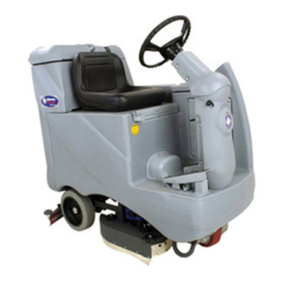
Advenger
™
3210D, 2400C, 2600C, 2810C, 3210C
BR 600S, 650S, 700S, 800S,
600CS, 650CS, 700CS, 800CS
SERVICE MANUAL
Advance MODELS 56314000, 56314001, 56314002, 56314003, 56314004,
56314005, 56314006, 56314007
Nilfi sk MODELS 56314010, 56314011, 56314012, 56314013, 56314014,
56314015, 56314016, 56314017
2400D, 2600D, 2810D,
3/03 revised 5/06 Form Number 56043088
Advertisement
Table of Contents
Troubleshooting


Need help?
Do you have a question about the Advenger 2400D and is the answer not in the manual?
Questions and answers