Table of Contents
Advertisement
Quick Links
Advertisement
Table of Contents

Related Manuals for Condair SH2


Summary of Contents for Condair SH2
- Page 1 Humidifiers InstallatIon and operatI ng InstructIons...
-
Page 3: Table Of Contents
Electric installation 4.4.1 Leading the electric cables out of the duct 4.4.2 Mounting the control unit SH2 4.4.3 Wiring diagram Condair SH2 flow C 4.4.4 Wiring diagram Condair SH2 flow SC 4.4.5 Wiring diagram Condair SH2 REflow C 4.4.6 Wiring diagram Condair SH2 REflow SC... -
Page 4: Introduction
We thank you for having purchased the Adiabatic Air Humidifier Condair SH2. The adiabatic air humidifier Condair SH2 incorporates the latest technical ad van ces and meets all recognized safety standards. Nevertheless, improper use of the adiabatic air humidifier Condair SH2 may result in danger to the user or third parties and/or impairment of material assets. - Page 5 If the equipment changes hands, the documentation must be passed on to the new operator. If the documentation gets mislaid, please contact your Condair supplier. Language versions These installation and operating instructions are available in various languages. Please contact your Condair supplier for information.
-
Page 6: For Your Safety
For safety and warranty reasons any action beyond the scope of this manual must be carried out only by qualified personnel authorised by the manufacturer. It is assumed that all persons working with the Condair SH2 are familiar and comply with the ap- propriate regulations on work safety and the prevention of accidents. - Page 7 Behaviour in case of danger If it is suspected that safe operation is no longer possible, then the Condair SH2 should immedi- ately be shut down and secured against accidental power-up according to chapter 5.4. This can be the case under the following circumstances: –...
-
Page 8: Product Overview
Product overview Model overview The Condair SH2 is available in the two base versions “flow” with direct water system and “REflow” with circulating water system. The following base models are available: – Condair SH2 flow – Condair SH2 flow C (with control unit RC and On/Off control) –... - Page 9 Type key Example: Condair SH2 REflow SC 300 1800 2000 0 150 Model: flow flow C flow SC REflow REflow C REflow SC Depth of humidification box: 200 mm 300 mm Order code width W Order code height H Mist eliminator:...
-
Page 10: Model "Flow
Model “flow” 3.3.1 Construction model “flow” Water connection on unit R 3/4" (outside thread) Volume controlling valves (adjustable manually) Water tub Open drain (ø 40/34 mm) Water hoses Trickling hoods with distribution pipes Humidification boxes Mist eliminator (for air speed above humidification boxes >3.8 m/s) -
Page 11: System Overview Model "Flow
3.3.2 System overview model “flow” Volume controlling valves (adjustable manually) Humidification boxes Water tub Supply valve (building side) Open drain Water connection unit (accessory) Water filter Siphon (building side) Pressure reducing valve Drain funnel (building side) Shut-off valve Control: via humidistat that actuates the supply valve depending on the humidification requests Water supply 2...10 bar Functional description... -
Page 12: Model "Flow C
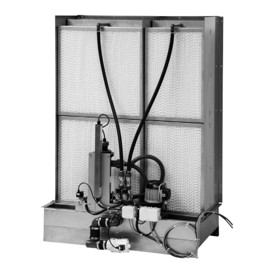
Model “flow C” 3.4.1 Construction model “flow C” Water connection on unit R 3/4" (outside thread) Volume controlling valves (adjustable manually) Water tub Open drain (ø 40/34 mm) Water hoses Trickling hoods with distribution pipes Humidification boxes Mist eliminator (for air speed above humidification boxes >3.8 m/s) Control unit RC... -
Page 13: System Overview Model "Flow C
3.4.2 System overview model “flow C” Volume controlling valves (adjustable manually) Humidification boxes Supply valve Water tub Open drain Output: Supply valve Water connection unit (accessory) Control unit RC Water filter Siphon (building side) L1 N Pressure reducing valve Drain funnel (building side) Humidistat 230V/2A Shut-off valve Input:... -
Page 14: Model "Flow Sc
Volume controlling valves (adjustable manually) Step valves (1 to 3) Water tub Open drain (ø 40/34 mm) Water hoses Trickling hoods with distribution pipes Humidification boxes Mist eliminator (for air speed above humidification boxes >3.8 m/s) UV water treatment (option) Control unit SH2... -
Page 15: System Overview Model "Flow Sc
The “flow SC” model provides multistep control by means of the SH2 control unit and the step valves (1, 2 or 3 step valves depending on the humidifier capacity). The SH2 control unit (for wall mounting) processes analog sensor/control signals and uses them to control the step valves. This allows multistep control (1 to 3 steps depending on the humidifier capacity) which improves control accuracy compared to the “flow”... -
Page 16: Model "Reflow
Model “REflow” 3.6.1 Construction model “REflow” Water connection on unit R 3/4" (outside thread) Level-controlled supply valve Circulation pump Volume controlling valves (adjustable manually) Overflow Drain (ø 40/34 mm) Shut-off valve Water tub Drain line Water hoses Trickling hoods with distribution pipes Humidification boxes Mist eliminator (for air speed above humidification boxes >3.8 m/s) CAUTION! -
Page 17: System Overview Model "Reflow
3.6.2 System overview model “REflow” Volume controlling valves Humidification boxes (adjustable manually) Circulation pump Level-controlled supply valve Overflow Water level Water tub Water connection unit (accessory) Shut-off valve Water filter Control: Via humidistat switching the circulation pump on or off depending on humidification Pressure reducing valve Siphon (building side) request... -
Page 18: Model "Reflow C
Level-controlled supply valve Circulation pump Overflow Drain (ø 40/34 mm) Drain valve Volume controlling valves (adjustable manually) Water tub Water hoses Trickling hoods with distribution pipes Humidification boxes Mist eliminator (for air speed above humidification boxes >3.8 m/s) Control unit SH2... -
Page 19: System Overview Model "Reflow C
The “REflow C” model provides On/Off control by means of the SH2 control unit and an external On/Off humidistat. In case of a humidification/cooling request one, two or all three step valves open (depending on the request). -
Page 20: Model "Reflow Sc
Drain valve Step valves (1 to 3) Volume controlling valves (adjustable manually) Water tub Water hoses Trickling hoods with distribution pipes Humidification boxes Mist eliminator (for air speed above humidification boxes >3.8 m/s) UV water treatment (option) Control unit SH2... -
Page 21: System Overview Model "Reflow Sc
The “REflow SC” model provides multistep control by means of the SH2 control unit and the step valves (1, 2 or 3 step valves depending on the humidifier capacity). The SH2 control unit (for wall mounting) processes analog sensor/control signals and uses them to control the step valves. This allows multistep control (1 to 3 steps depending on the humidifier capacity) which improves control accuracy compared to the “REflow”... -
Page 22: Standard Delivery
UV water treatment unit where it is degerminated. Standard delivery The standard delivery includes: – Adiabatic air humidifier Condair SH2 according type designation (delivered apart) equipped with options according delivery note. – Ordered accessories with operating instructions, packed separately. -
Page 23: Installation
Usually, the design and dimensioning of the ventilation duct/monobloc as well as the location of the Condair SH2 inside the duct are determined, recorded and set compulsory when planning the entire system. Prior to installation, however, make sure the following criteria have been taken into consideration: –... - Page 24 – We recommend to install air filter (quality standard F7 (EU7) or better) before the humidification unit. The operation without air filter or with a filter of lower quality is possible, this can however, depending on the air quality, lead to an increased contamination of the humidifier boxes and thus to a reduction of the performance/lifetime.
-
Page 25: Mounting Process
4.2.2 Mounting process 1. Fix the mounting brackets “A” to the water tub using one nut M6 and washer for each bracket. Align the water tub to the centre of the duct, then use the spirit level to adjust the water tub to the duct lengthwise and crosswise. - Page 26 Hint: With close space conditions we recommend to install the EPDM sealing profile to the vertical supports before installing the supports. Please refer to step 7 for more information. 3. Carefully mount the left “D” and the right vertical support “E” onto the threaded bolts of the water tub, then fix each support with four nuts M6 and washers (do not overtighten the nuts).
- Page 27 4. Carefully mount the vertical intermediate support(s) “F” (number depending on the unit size) onto the threaded bolts of the water tub, then fix each support with two nuts M6 and washers to the water tub (do not overtighten the nuts) and with a hexagon socket screw M6x12 and a washer to the cross beam.
- Page 28 5. Fix the front bracket “G” to each vertical support using two hexagon socket screws M6x12 and washers. Important! Before tightening the screws make sure all supports are vertically exactly aligned!
- Page 29 6. Fix one mounting bracket “H” to each vertical support and intermediate support using a hexagon socket screw M6x12, a nut M6 and a washer (see figure above). Important: With multiple inter- mediate supports all mounting brackets must be mounted to the supports on the same side. The mounting brackets fixed to the outermost supports must be mounted always outside (between duct wall and support) and point inward.
- Page 30 7 . The air gap between the outermost vertical supports and the duct walls as well as between the front bracket and the duct ceiling must be sealed using EPDM sealing profile (accessory). Cut the EPDM sealing profiles to the desired length (channel height and channel width plus 5 cm allowance).
- Page 31 8. Fix hydraulic unit to the water tub and the cross beam using four hexagon socket screws M6x12 and washers. Important: Remove the closing plug “H” from the circulation pump inlet before mounting the hydraulic units REflow, REflow C or REflow SC.
- Page 32 flow REflow C flow C REflow REflow SC flow SC remains open Important: Insert the hose at least 20–30 mm into the opening! 9. Assemble the drains according to the corresponding figure above (the drains can be assembled for draining to the right or to the left) and fix it to the connector(s) of the water tub. Fasten all threaded connections and hose clamps and fix the drain pipe to the water tub with the pipe sup- port supplied.
- Page 33 10. Starting from the bottom, install the humidification boxes in each row: Hook the mounting clips of the boxes into the corresponding openings of the supports, then push the humidification box downwards until it comes to a stop (arrangement of the humidification boxes according to the installation drawing included in the delivery).
- Page 34 11. Only for units with mist eliminator: Hook the mounting brackets into corresponding openings of the vertical supports, then push the brackets downwards until it comes to a stop (if necessary use a rubber mallet). Note: arrangement of the mounting brackets according to the detail figures above and the instal- lation drawing included in the delivery.
- Page 35 12. Only for units with mist eliminator: Starting from the bottom, install the mist eliminator in each row: Hook the mounting clips of the mist eliminator into the corresponding openings of the mounting brackets, then push the mist eliminator downwards until it comes to a stop. Note: arrangement of the mist eliminator according to the installation drawing included in the delivery.
- Page 36 13. Mounting the trickling hoods: Push the two tongues on the back side of the trickling hood under- neath the frame sheet of the humidification box (see detail above), then flap the trickling hood downwards. The two brackets on the front side of the trickling hood must engage in the frame (see detail above) of the humidification box.
- Page 37 Remove the closing plugs from the connections of the hydraulic unit. Cut the water hoses to the required length. Connect water hoses to the connectors on the trickling hoods and the volume controlling valves and fix them with the hose clamps. Note: arrangement of the water hoses according to the installation drawing included in the de- livery.
-
Page 38: Water Installation
Water installation 4.3.1 Overviews water installation Model “flow” R 3/4" Supply valve (building side) ø 40/34 mm Water connection unit (accessory) Drain line with constant down-slope Water filter Siphon (building side, height adjusted to the duct pressure) Pressure reducing valve Open funnel (building side) Shut-off valve Water supply... - Page 39 Model “flow SC” R 3/4" ** installation mandatory ø 40/34 mm Water connection unit ** (standard delivery) Water filter Drain line with constant down-slope Siphon (building side, height Pressure reducing valve adjusted to the duct pressure) Open funnel (building side) Shut-off valve Water supply 2...10 bar...
- Page 40 Models “REflow C” and “REflow SC” R 3/4" Water connection unit (accessory) Water filter Pressure reducing valve Shut-off valve ø 40/34 mm Water supply 2...10 bar Siphon (building side, height Drain line with constant down-slope 5...45 °C adjusted to the duct pressure) Open funnel (building side)
-
Page 41: Notes On Water Installation
– Notes on water quality: – For the water supply of the Condair SH2, use exclusively untreated drinking water, fully dem- or partly softened water with a max of 100 cfu/ml. ineralised water, fully softened water –... -
Page 42: Electric Installation
Electric installation Note: the electric installation of the unit models Condair SH2 “flow” and “REflow” is by the clients responsibility. 4.4.1 Leading the electric cables out of the duct Lead the cable(s) of the connecting boxe(s) via cable gland(s) out of the duct. -
Page 43: Mounting The Control Unit Sh2
4.4.2 Mounting the control unit SH2 CAUTION! The electronic components inside the control unit are very sensitive to electrostatic discharge. When the unit is open for installation work, appropriate measures must be taken to protect these components against damage caused by electrostatic dis- charge (ESD protection). -
Page 44: Wiring Diagram Condair Sh2 Flow C
4.4.3 Wiring diagram Condair SH2 flow C Humidistat or thermostat (230V/2A) Safety humidistat (Safety chain) External fuse 2 A, slow acting (voltage supply) Inlet valve Connecting box Service switch (min. contact opening 3 mm) or plug connection (installation mandatory) Control unit RC L1 N cross section 1.5 mm... -
Page 45: Wiring Diagram Condair Sh2 Flow Sc
4.4.4 Wiring diagram Condair SH2 flow SC brown brown white white Reserve Output 200mAF 200mAF brown blue 230 V brown blue UV Lamp brown Drain Valve blue Connector Inlet Valve to CPU green/yellow Stage 3 brown blue 6.3AT Stage 2... -
Page 46: Wiring Diagram Condair Sh2 Reflow C
4.4.5 Wiring diagram Condair SH2 REflow C black brown brown black white 24 V Reserve Output 200mAF 200mAF 230 V brown blue UV Lamp brown Drain Valve blue Connector Inlet Valve to CPU green/yellow Stage 3 6.3AT Stage 2 Stage 1... -
Page 47: Wiring Diagram Condair Sh2 Reflow Sc
4.4.6 Wiring diagram Condair SH2 REflow SC – + black brown brown black white 24 V Reserve Output 200mAF 200mAF brown blue 230 V brown blue UV Lamp brown Drain Valve blue Connector Inlet Valve to CPU green/yellow Stage 3... -
Page 48: Operation
3. Open the shut-off valve in the water supply line. 4. Switch on the service switch in the mains supply. 5. Models flow SC, REflow C and REflow SC: switch on the control unit SH2 (the unit switch lights up). -
Page 49: Notes On Operation
Note: if the Condair SH2 is not be used for a longer period of time the models flow, flow C and RE- flow should be taken out of operation as described above. However, the models flow SC, REflow C and REflow SC should stay operable to keep the hygiene functions (e.g. -
Page 50: Maintenance
WARNING! If the unit is insufficient maintained ill-making germs may grow in the water tub and the humidi- fication boxes (and the mist eliminator) of the Condair SH2 and may can affect the air passing through the humidifier. -
Page 51: Maintenance Intervals
In any case the Condair SH2 is to be maintained however at least twice annually. On units equipped with a SH2 control unit (flow SC, REflow C and REflow SC) the maintenance interval can be programmed. As soon as the maintenance time has elapsed, a maintenance mes- sage is displayed to draw your attention to the pending maintenance. - Page 52 Check water the water hoses of the humidifier for cracks and Water installation correct fastening, replace defective hoses. Carefully clean the hoses with a combined detergent and dis- infectant. Check water supply line for sealing and seal if necessary. Dis- mantle water filter (if present), clean it, then reinstall Dismantle the trickling hoods and check the holes in the water...
-
Page 53: Dismantling And Installation Works
Dismantling and installation works 6.4.1 Dismantle and install the mist eliminator and humidification boxes 1. Undo the hose clamps, then pull off the hoses from the connections on the trickling hoods. 2. Lift the trickling hoods on the water connection side and remove them to the front. -
Page 54: Dismantle And Install The Uv Lamp (Option)
When maintenance work has been completed the maintenance indication must be reset on the unit models flow SC, REflow C and REflow SC (yellow LED lights). For that purpose, please observe the information given in the separate operating instructions for the SH2 control unit. -
Page 55: Malfunctions
Note: On units equipped with a SH2 control unit (flow SC, REflow C and REflow SC) malfunctions dur- ing operation are indicated by a corresponding event message in the display. For that purpose, please... -
Page 56: Notes On Fault Elimination
Notes on fault elimination DANGER! In order to eliminate faults, the Condair SH2 must be set out of operation as described in chapter 5.4. Disconnect the unit from the mains and secure the unit against inadvertent power-up. Only allow trained and qualified personnel to repair faults. Faults relating to electrical installation must only be carried out by authorized personnel or your Condair representative’s service technician. -
Page 57: Taking Out Of Service/Disposal
Taking out of service/Disposal Taking out of service If the Condair SH2 must be replaced or if the humidification system is not needed any more, pro- ceed as follows: 1. Take the unit out of operation as described in chapter 5.4. -
Page 58: Product Specifications
Product specifications Technical data Condair SH2 models flow flow C flow SC REflow REflow C REflow SC Control ––– Control RC Control SH2 ––– Control SH2 Control SH2 Control supply voltage ––– 230 VAC/50 Hz 230 VAC/50 Hz ––– 230 VAC/50 Hz... -
Page 59: Unit Dimensions
Unit dimensions Unit dimensions flow R 3/4" ø40/36 645 ...3945 mm (graduation 75 mm) UW : 604 ...4104 mm (graduation 100 mm) Max. humidification Depth Depth Depth UD efficiency Humidification box Mist eliminator 85 % 200 mm ––– 581 mm 85 % 200 mm 100 mm... - Page 60 Unit dimensions flow C ø40/36 645 ...3945 mm (graduation 75 mm) UW : 604 ...4104 mm (graduation 100 mm) Max. humidification Depth Depth Depth UD efficiency Humidification box Mist eliminator 85 % 200 mm ––– 581 mm 85 % 200 mm 100 mm 581 mm 85 %...
- Page 61 Unit dimensions flow SC R 3/4" ø40/36 645 ...3945 mm (graduation 75 mm) UW : 604 ...4104 mm (graduation 100 mm) Max. humidification Depth Depth Depth UD efficiency Humidification box Mist eliminator 85 % 200 mm ––– 581 mm 85 % 200 mm 100 mm 581 mm...
- Page 62 Unit dimensions REflow R 3/4" ø40/36 645 ...3045 mm (graduation 75 mm), >3045 mm on request UW : 604 ...4104 mm (graduation 100 mm) Max. humidification Depth Depth Depth UD efficiency Humidification box Mist eliminator 85 % 200 mm ––– 581 mm 85 % 200 mm...
- Page 63 Unit dimensions REflow C R 3/4" ø40/36 645 ...3045 mm (graduation 75 mm), >3045 mm on request UW : 604 ...4104 mm (graduation 100 mm) Max. humidification Depth Depth Depth UD efficiency Humidification box Mist eliminator 85 % 200 mm –––...
- Page 64 Unit dimensions REflow SC R 3/4" ø40/36 645 ...3045 mm (graduation 75 mm), >3045 mm on request UW : 604 ...4104 mm (graduation 100 mm) Max. humidification Depth Depth Depth UD efficiency Humidification box Mist eliminator 85 % 200 mm –––...
- Page 65 Notes...
- Page 66 Notes...
- Page 67 © condair ltd., printed in switzerland technical modifications reserved...
- Page 68 40002-2 Manufacturer: condair ltd. Member of the Walter Meier group talstrasse 35-37, 8808 pfäffikon, switzerland ph. +41 55 416 61 11, Fax +41 55 416 62 62 info@condair.com, www.condair.com...
Need help?
Do you have a question about the SH2 and is the answer not in the manual?
Questions and answers