Condair RS series Operation Manual
Steam
Hide thumbs
Also See for RS series:
- Operation manual (84 pages) ,
- Installation manual (80 pages) ,
- Installation, operation and maintenance manual (68 pages)

Related Manuals for Condair RS series


Summary of Contents for Condair RS series
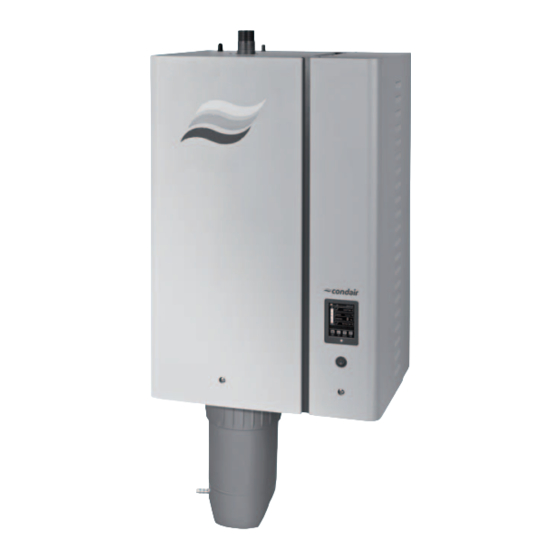
- Page 1 OPERATION MANUAL Steam humidifier Condair RS Humidification and Evaporative Cooling...
- Page 2 Condair Ltd., except to the extent required for installation or maintenance of recipient's equipment. Liability Notice Condair Ltd. does not accept any liability due to incorrect installation or operation of the equipment or due to the use of parts/components/equipment that are not authorized by Condair Ltd.
-
Page 3: Table Of Contents
For your safety Product Overview Construction Condair RS steam humidifier Functional description System overview Condair RS for duct humidification System overview Condair RS for direct room humidification Operation First-time commissioning Display and operating elements Commissioning after an interruption of operation Notes on operation 4.4.1... - Page 4 Important notes on maintenance Maintenance intervals Maintenance list Removing and installing components for maintenance 6.4.1 Preparing the Condair RS for the removal of components 6.4.2 Removal and installation of the scale collector tank 6.4.3 Removal and installation of the steam cylinder 6.4.4...
-
Page 5: Introduction
To the very beginning We thank you for having purchased the Condair RS steam humidifier. The Condair RS steam humidifier incorporates the latest technical ad van ces and meets all recognized safety standards. Nevertheless, improper use of the Condair RS steam humidifier may result in danger to the user or third parties and/or damage to property. - Page 6 If the documentation gets misplaced, please contact your Condair partner. Language versions This operation manual is available in other languages. Please contact your Condair partner for information. Introduction...
-
Page 7: For Your Safety
Condair RS safely and correctly. All icons, signs and markings applied to the components of the Condair RS must be observed and kept in readable state. - Page 8 Prevention: Do not carry out any work on the steam system during operation (steam lines, steam distributor, blower pack, etc.). If the steam system is leaky set the Condair RS immediately out of op- eration as described in chapter 4.5 –...
-
Page 9: Product Overview
Driver board Filling cup Ground terminals Condensate connector (to cylinder) Main contactor Condensate connector (to drain) Heating contactors Steam connector (ø45 mm) Power board Steam outlet hose Fig. 1: Construction Condair RS steam humidifier (figure shows medium sized unit) Product Overview... -
Page 10: Functional Description
Functional description The Condair RS steam humidifier is an atmospheric steam generator. It operates on the resistance heating principle and is designed for direct room air humidification (with blower pack) and indirect humidification (with steam distributor) in venti lating and air-conditioning systems. -
Page 11: System Overview Condair Rs For Duct Humidification
15 Steam distributor (accessory DV81) 7 Manometer (recommended) 16 Humidity controller or humidity sensor 8 Open funnel with water trap 17 Humidity controller or humidity sensor 9 Drain line 18 High limit humidistat Fig. 2: System overview Condair RS for duct humidification Product Overview... -
Page 12: System Overview Condair Rs For Direct Room Humidification
13 Condensate line (accessory KS10) Filter valve (accessory Z261) 14 Blower Pack (accessory BP) Manometer (recommended) 15 Humidity controller or humidity sensor Open funnel with water trap 16 High limit humidistat Fig. 3: System overview Condair RS for direct room humidification Product Overview... -
Page 13: Operation
Operation The Condair RS steam humidifier may be commissioned and operated only by persons familiar with the Condair RS steam humidifier and adequately qualified. It is the owner’s responsibility to verify proper qualification of the personnel. First-time commissioning The first-time commissioning must always be done by a service technician of your Condair partner or a well trained and authorised person of the customer. -
Page 14: Display And Operating Elements
Touchscreen Status LED – green: Condair RS is humidifying – green pulsing: Condair RS is in standby operation – orange: Warning present or maintenance due – red: Fault present Unit switch Fig. 4: Display and operating elements... -
Page 15: Commissioning After An Interruption Of Operation
If the function check on the level unit is successful, the Condair RS will be in normal operating mode and the standard operating display is shown. The heating current switches on as soon as the humidity controller/humidistat demands humidity. The LED lights green and steam is produced after a short delay. -
Page 16: Notes On Operation
The drain cycle is stopped and the unit returns to the "Manual" submenu. 4. If you have to carry out work on the Condair RS, switch off steam humidifier via the unit switch. Otherwise the steam cylinder is immediately filled again. -
Page 17: Taking The Unit Out Of Operation
Taking the unit out of operation In order to take the Condair RS steam humidifier out of operation (e.g. for maintenance purpose), per- form the following steps: 1. Close the shut-off valve in the water supply line. 2. If you have to carry out maintenance work on the steam cylinder and/or on the scale collector tank perform a cylinder draining (see chapter 4.4.2 –... -
Page 18: Operating The Control Software
Operating the control software Standard operating display After switching on the Condair RS and the automatic system test the steam humidifier is in normal operating mode and the standard operating display is shown. Note: the appearance of the standard operating display depends on the current operating status and the configuration of the humidity control of the system and can deviate from the display shown below. -
Page 19: Operating Status Indication
A malfunction with status "Warning" is active. Additionally the yellow LED lights. Depending on the malfunction the Condair RS is either be stopped or stays operable for a certain period of time. A malfunction with status "Fault" is active. Additionally the red LED lights. Depending on the malfunction the Condair RS is either be stopped or stays operable for a certain period of time. -
Page 20: Navigating/Operating The Control Software
Navigating/Operating the control software Navigation element Action Accessing main menu Accessing system informations Performing manual steam cylinder draining Accessing help screen If you press on a field with a blue arrow symbol a new screen with additional informations or settings appears. This symbol on the left side of the operating status field and of the mainte- nance/malfunctions indication field indicates, that the system is working ok. -
Page 21: Information Functions
Information functions 5.3.1 Accessing support informations In the standard operating display press the <Help> button. The screen with the support information appears. 5.3.2 Accessing system informations In the standard operating display press the <About> button. The system information screen appears. Use the arrow buttons to scroll up and down within the system information screens to access the different system information and operating data. - Page 22 Serial Number: Serial number of the steam humidifier. Diagram: With this function you can access the graphical display of the – performance diagram of the Condair RS. – Export Trend Data: With this function you can save the data of the per- formance diagram as .csv file to a USB memory stick.
- Page 23 Operating – Capacity: Actual total steam capacity of the steam humidifier in kg/h or lb/h. Control Mode CH 1/3: Actual set control signal type ("On/Off", "Demand", – "RH P" or "RH PI"). – System Demand A: Actual system demand in %. –...
- Page 24 Node ID: Actual set BACnet Node ID. Note: this menu item appears only, if BACnet communication is set to "BACnet IP". – Online Status: Actual online status of the Condair RS ("Connected" or "Disconnected"). – IP Address: Actual set IP address of the Condair RS.
-
Page 25: Configuration
Accessing the "Configuration" submenu Password: 8808 5.4.2 Activating/deactivating and configuration of options – "Features" submenu In the "Features" submenu you can determine different operating parameters of the Condair RS. Water Management – Water Mode: with this setting you determine whether the flushing interval time and the maintenance interval time for the small and the extended maintenance are calculated automatically on the basis of parameters water quality and water hardness (Setting: "Calculated") or whether the... - Page 26 Standard settings dependent on the water quality Steam Water reduction time Maintenance interval time capacity Small Maintenance Extended Maintenance Tap water * RO water ** DI water *** Tap water * RO water ** Tap water * RO water ** DI water *** DI water *** 5 kg/h...
- Page 27 Idle Mode – Idle Mode: with this setting you determine the operational behaviour of the Condair RS in standby operation. Idle Drain Factory setting: Idle Drain or Keep Warm Options: The following settings appear only, if "Idle Mode" is set to "Idle Drain".
- Page 28 Softstart – Softstart Mode: with this setting you can activate ("On") or deactivate ("Off") the softstart function. Factory setting: Options: On or Off Note: activate the soft start function if you are using softened water or water with a high conductivity. Note: if the softstart function is activated the humidification capacity is reduced to a preset value for a select able period if a demand is present after restarting the steam humidifier or after more than 4 hours in standby...
- Page 29 – Manual Capacity A: with this button you can access the settings menu for the capacity limitation. Here you determine whether the Condair RS is to be operated with a fix capacity limitation (factory setting) or whether it is to be operated with a timer controlled capacity limitation.
- Page 30 – ON/Off Timers: with this button you can access the settings menu for the On/Off timer. With the "Timer" parameter you can activate ("On") or deactivate ("Off") the On/Off timer. If the timer is activated, up to eight switching points (Event 1... Event 8) with different On/Off events can be defined.
- Page 31 ("Off") the optional drain valve for the automatic draining of the scale col- lector tank in standby operation. Note: if the optional drain valve is activated, the Condair RS is completely drained in standby operation (including scale collector tank) and refilled only after a humidity demand is present again.
- Page 32 Accessory Board Note: the "Accessory Board" tap with the corresponding settings appears only, if the optional accessory board (for the control of an external fan of the ventilation system or the optional valve for flushing the water supply line) is installed and activated in the factory level. –...
-
Page 33: Humidity Control Settings - "Control Settings" Submenu
BACnet/IP (Signal via BACnet/IP) BACnet/MS (Signal via BACnet MSTP) LonWorks (Signal via LonWorks) – Control Mode CH 1/3: with this setting you determine the type of control- ler used with the Condair RS. Factory setting: Demand Options: On/Off (external On/Off humidistat) - Page 34 – Setpoint Channel 1: with this button you can access the settings menu for the humidity setpoint. Here you determine whether the Condair RS is to be controlled with a fix humidity setpoint (factory setting) or whether it is to be operated timer controlled with different humidity setpoints.
- Page 35 Configuration notes: – the settings of an event remain active up to the next event. – the software does not c heck the plausibility of the timer settings. Therefore, make sure your settings make sense. – the On/Off timer overrides the humidity setpoint timer. –...
- Page 36 Factory setting: Setting range: 1 ... 10 % Remote Enable – Enable Input: With this setting you determine wether the Condair RS can be enabled and disabled via an external enable contact ("On") or not ("Off"). Factory setting: On or Off...
- Page 37 Multi Unit Operation – Linkup: with this setting you determine whether the unit is part of a Linkup system and acts as master or slave unit or whether the unit is not part of a Linkup system. Note: the master unit must be set always to "Main". The further slave units in the chain must be set in ascending order to "Ext1"...
- Page 38 – Sequence Interval: with this setting you determine the interval time the control system compares the operating hours of the cylinders in order to change the starting order if sequential cylinder rotation activated. Note: this setting appears only, if the "Sequence Rotation" function is activated ("On").
-
Page 39: Basic Settings - "General" Submenu
5.4.4 Basic settings – "General" submenu In the "General" submenu you determine the basic settings for operating the Condair RS control software. Basic – Date: with this setting you determine the current date in the set format ("MM/DD/YYYY" or "DD/MM/YYYY"). Factory setting: 00/00/0000 –... -
Page 40: Communication Settings - "Communication" Submenu
5.4.5 Communication settings – "Communication" submenu In the "Communication" submenu you determine the parameters for the communication. Remote Enable – Allow Remote Disable: with this setting you can activate ("Yes") or de- activate ("No") remote blocking via the BMS. Factory setting: Options: Yes (Remote blocking permitted) No (Remote blocking not permitted) Network Parameters The following network settings are use only for the communication via the... - Page 41 The following parameters appear only if the Modbus function is activated. – Modbus Address: with this setting you determine the Modbus address for the Condair RS for the communication via a Modbus network. Factory setting: Setting range: 1 ... 247 –...
- Page 42 The following settings appear only, if the parameter "BACnet" is set to "BACnet/IP". – Device Name: with this setting you determine the name of the Condair RS for the communication via the integrated BACnet interface. – Device Description: with this setting you determine a short descrip- tion of the unit.
- Page 43 – Device Description: with this setting you determine a short descrip- tion of the unit. – Device Location: with this setting you determine the designation of the unit location. – Node ID: with this setting you determine the Node ID. –...
-
Page 44: Maintenance Functions
Maintenance functions 5.5.1 Accessing the "Service" submenu Password: 8808 5.5.2 Performing maintenance functions – "Service" submenu In the "Service" submenu you can reset the maintenance counters, access the fault and maintenance history and perform different diagnostic functions. General Service – Small Maint. Reset A: with the"Small Maint. Reset A" function you can reset the service message or the service counter, respectively for the small maintenance of unit A. -
Page 45: 5.5.2.1 - Input Diagnostic Functions - "Input Diagnostics" Submenu
Fault/Service History Note: the fault and maintenance events stored can be correctly analysed only if the data and the time of day are correctly set. – Fault History: with this function you can access the fault history list where the last 40 fault events are stored. After pressing on the "Fault History" button the fault history list appears. - Page 46 5.5.2.1 Input diagnostic functions – "Input Diagnostics" submenu The following input values can be viewed after accessing the "Input Diagnostics" submenu. Note: the input values can be accessed and viewed too, via the "Service Info" selection field in the standard operating display. Cylinder A/B – Channel 1: Set humidity setpoint in %rh for humidity contol. –...
-
Page 47: 5.5.2.2 Relay Diagnostic Functions - "Relay Diagnostics" Submenu
– 24V External Supply: Actual voltage of the external 24 V supply. – 10V External Supply: Actual voltage of the external 10 V supply. 5.5.2.2 Relay diagnostic functions – "Relay Diagnostics" submenu Remote Fault board – Running: with this function you can activate ("On") and deactivate ("Off") the relay "Steam"... -
Page 48: Administration Settings
Administration settings 5.6.1 Accessing "Administrator" submenu Password: 8808 5.6.2 Switching on/off password protection and software updates function - submenu "Administrator" In the "Administrator" submenu you can activate and deactivate the password protection for the main menu and the setpoint, and download software updates via a USB stick connected to the USB connector. Password settings Setpoint Password: with the function "Setpoint Password"... - Page 49 Software Settings – Software Update: with the function "Software Update" you can update the control software of the integrated controller. – Driver A.DB.A Update: with the function "Ext.A.DB.A Update" you can update the driver board software of steam humidifier A. –...
-
Page 50: Maintenance
Prevention: Before carrying out any work on the steam system set the Condair RS out of operation as described in operation, then wait until the components have chapter 4.5 –... -
Page 51: Maintenance Intervals
To maintain operational safety the Condair RS steam humidifier must be maintained at regular intervals. The control software of the Condair RS features two maintenance counters one for the "Small main- tenance" (Cleaning of the scale collector tank, only for units equipped with a scale collector tank) and one for the "Extended maintenance"... -
Page 52: Maintenance List
Maintenance list Adjacent you can find an overview of the maintenance work to be carried out on "Small maintenance" and "Extended maintenance". Components Work to be done Scale collector tank Remove and clean. Steam cylinder Remove, disassemble and clean, replace defective components if necessary. -
Page 53: Removing And Installing Components For Maintenance
6.4.1 Preparing the Condair RS for the removal of components Before starting any removal work set the Condair RS out of operation and drain the steam cylinder and the scale collector tank (if applicable). Proceed as follows: 1. Condair RS must be switched on. Perform a draining of the steam cylinder (see chapter 4.4.2 –... -
Page 54: Removal And Installation Of The Scale Collector Tank
6.4.2 Removal and installation of the scale collector tank Removal WARNING! Danger of burning! Before removal of the scale collector tank ensure it is empty and the temperature indication adhesive on the scale collector tank indicates a temperature <122 °F (<50°C) . Snap ring O-ring Strainer... - Page 55 Installation Prior to the installation: • Check scale collector tank, O-ring, snap ring and strainer insert for damages and replace defective components if necessary. We recommend to replace the sealings of the scale collector tank with each maintenance. For that purpose a maintenance kit is available (see parts list). •...
-
Page 56: Removal And Installation Of The Steam Cylinder
6.4.3 Removal and installation of the steam cylinder WARNING! Danger of burning! Before removal of the steam cylinder ensure the steam cylinder is empty and has cooled down, that no more burning danger exists. 1. Loosen retaining screw on front door on the steam cylinder side of the unit using a screwdriver, then remove the front door. - Page 57 3. Carefully lift the steam cylinder out of steam cylinder receptacle and remove it towards the front of the unit. CAUTION! Set down the steam cylinder carefully to ensure the funnel on the bottom side of the cylinder is not damaged! 4.
- Page 58 6. If necessary, loosen the funnel insert by lightly rotating it in either direction and lift it together with baffle from the steam cylinder. Then, remove the screen insert from the funnel insert. 7. If during maintenance one or more heating elements must be replaced: •...
-
Page 59: Removal And Installation Of The Drain Cup
Assembly and installation of the steam cylinder Assembly of the steam cylinder takes place in reverse sequence of the removal. Please note the fol- lowing instructions: – Installation of any heating elements which have been removed should follow the figure of step 7. Please take care that the heating elements are correctly positioned and the cables are correctly connected (according to your notes). -
Page 60: Removal And Installation Of The Filling Cup, The Level Unit And The Water Hoses
6.4.5 Removal and installation of the filling cup, the level unit and the water hoses For removing the filling cup, the level unit and the water hoses the steam cylinder must be removed first (see chapter 6.4.3). 1. Release hose clamps, then disconnect all hoses from the corresponding connectors and remove the hoses. Note: The hoses connected to the filling cup and the level unit may also be removed together with the filling cup and the level unit (see illustration) and then disconnected from the connectors outside the unit. -
Page 61: Removal And Installation Of The Drain Pump
6.4.6 Removal and installation of the drain pump For removing the drain pump the steam cylinder must be removed first (see chapter 6.4.3). 1. Detach electric cables (polarity of the cables must not be observed). 2. Release hose clamps and remove the hoses from the connectors. 3. -
Page 62: Removal And Installation Of The Inlet Valve
6.4.7 Removal and installation of the inlet valve For removing the inlet valve the steam cylinder must be removed first (see chapter 6.4.3). 1. Detach electric cables (polarity of the cables must not be observed). Important: on multiple valves (units with increased control accuracy or units with option drain cooling) ensure to reconnect the connecting cables to same valve (note position). -
Page 63: Removal And Installation Of The Steam Cylinder Receptacle
6.4.8 Removal and installation of the steam cylinder receptacle For removing the steam cylinder receptacle the steam cylinder must be removed first (see chapter 6.4.3). 1. Release hose clamps and remove hoses from the connectors. 2. Undo the screw fixing cylinder receptacle to the bottom of the housing with Phillips screwdriver. 3. -
Page 64: Notes On Cleaning The Unit Components
Notes on cleaning the unit components Unit component What to clean and how to clean Scale collector tank • Dump any lime in scale collector tank, then carefully knock off any limescale inside scale collector tank and on the strainer insert. If the scale collector tank heavily calcified, fill scale collec- tor tank with an 8% formic acid solution (observe safety notes in... - Page 65 Unit component What to clean and how to clean Hoses • Remove any limescale by slightly knocking on the tubes using a rubber hammer. Then, rinse the tubes well with hot tap water. Inlet valve • Use a soft bristled brush (do not use a wire brush) to remove any limescale inside the inlet valve and on the strainer.
-
Page 66: Notes On Cleaning Agents
Unit component What to clean and how to clean Drain cup • Use a soft bristled brush (do not use a wire brush) to remove any limescale from the drain cup and its con- nectors. If the drain cup is heavily calcified, place it in an 8% formic acid solution (observe safety notes in chapter 6.6), until the limescale comes off. -
Page 67: Resetting The Maintenance Counter
Resetting the maintenance counter After completing the "Small maintenance" or the "Extended maintenance", the corresponding mainte- nance indication or maintenance counter (for module A or module B or for both), respectively must be reset. Proceed as follows to reset the maintenance counter: 1. -
Page 68: Fault Elimination
LED below the touch panel light up. If such a malfunction occurs the operation of the system is limited only or the Condair RS will be stopped automatically. -
Page 69: Malfunction List
––– Max. Filling Time The Condair RS is monitoring the filling process with different levels which have to be reached within a preset time during filling. If a certain level is not reached within the preset time the fault message "Max. Filling Time" is triggered. - Page 70 Replace drain pump. ––– Invalid Level Invalid level detected, humidification is stopped! Note: As soon as the level is within the valid range again, the Condair RS con- tinuous normal operation. Magnetic field in vicinity of level unit. Eliminate magnetic field.
- Page 71 ––– No Heating voltage Heating voltage missing although a demand is present. Note: As soon as the heating voltage is present again, the Condair RS continu- ous normal operation. Main contactor defective. Let have the main contactor be checked/ replaced by an electrician Phase failure heating voltage supply.
- Page 72 Maintain maximum steam line lengths (max. 4 m), Insulate steam line. This error may also occur upon a Enable Soft start function. cold start These fault messages must be reset by switching the Condair RS off and on again (see chapter 7.5) Fault elimination...
-
Page 73: Notes On Fault Elimination
DANGER! Make sure the Condair RS is separated from the mains (check with voltage detector) and the shut-off valve in the water supply line is closed. – The elimination of faults must be carried out by qualified and well trained professionals only. -
Page 74: Replacing The Fuses And Backup Battery In The Control Unit
Fig. 6: Position of the backup battery and the fuses on the driver board 5. Swivel control board assembly 90°inwards. 6. Relocate front cover on control unit and lock it with the retaining screw. 7. Reconnect Condair RS to the mains by switching on the electrical isolator.. Fault elimination... -
Page 75: Resetting The Fault Indication
To reset the error indication (red LED light, operating status indication shows "Stop"): 1. Switch off the Condair RS via the unit switch. 2. Wait approx. 5 seconds, then switch on the Condair RS again. Note: If the fault has not been eliminated, the fault indication reappears after a short while. -
Page 76: Taking Out Of Service/Disposal
Taking out of service/Disposal Taking out of service If the Cond air RS must be replaced or if the Condair RS is not needed any more, proceed as follows: 1. Take the Condair RS out of operation as described in chapter 4.5 –... -
Page 77: Product Specification
Product specification Performance data 230V/1~/50...60 Hz 200V/3~/50...60 Hz 230V/3~/50...60 Hz 400V/3~/50...60 Hz 415V/3~/50...60 Hz Condair kg/h kg/h kg/h kg/h kg/h ...5... 16.5 –– –– –– ...8... 26.0 –– –– –– 15.0 ...10... 32.0 12.1 26.1 18.5 11.0 10.7 11.5 ...16... –– –– –– 14.9 11.2 32.2 16.0... -
Page 78: Operating Data
1...40 °C (with optional drain water cooling 1...25 °C) – Water quality Untreated drinking water, RO water, de-ionized water (for operation with softened or partly softened water please contact your Condair partner) Water drain – Drain water temperature 60...90 °C... - Page 80 Condair GmbH Regionalcenter Süd Hauptsitz Deutschland Parkring 3 D-85748 Garching-Hochbrück Tel. +49 (0) 89 207 008-0 Fax +49 (0) 89 207 008-140 Regionalcenter Südwest Zettachring 6 70567 Stuttgart Tel.: (0) 711 25 29 70-0 Fax: (0) 711 25 29 70-40 Regionalcenter Mitte Nordendstrasse 2 D-64546 Mörfelden-Walldorf...
Need help?
Do you have a question about the RS series and is the answer not in the manual?
Questions and answers