Table of Contents
Advertisement
Advertisement
Table of Contents

Subscribe to Our Youtube Channel
Related Manuals for Condair SE Series


Summary of Contents for Condair SE Series
- Page 1 Your guide to selecting and specifying Condair Steam Exchange Humidifiers! Series Engineering Manual Includes technical specifications, guidelines, and options for selection and application of SETC B+ Steam Exchange humidifiers 2576599-A | 21 APR 2014...
- Page 2 Thank you for choosing Condair. Proprietary Notice This document and the information disclosed herein are proprietary data of CONDAIR AG / CONDAIR HUMIDITY LTD. Neither this document nor the information contained herein shall be reproduced used, or disclosed to others without the written authorization of CONDAIR AG / CONDAIR HUMIDITY LTD., except to the extent required for installation or maintenance of recipient’s equipment.
-
Page 3: Table Of Contents
Humidifier Specification Checklist ....14 Humidifier Load ..........15 Humidifier Controls ........18 Installation Location ........18 Steam Distribution Method ......19 SE Series Options and Accessories ..... 19 Sample Specification ........24 Location ............29 Indoor Location ..........30 Plumbing ............35 Boiler Steam &... -
Page 4: How The Humidifier Works
RO, or DI water to generate heat and steam. The main applications of SE series humidifiers is humidification of buildings which have a high pressure boiler which can also be used for heating or other industrial processes. SE humidifiers take the steam produced by the boiler, which contains anti-scaling chemicals, and utilizes it to produce clean and pure atmospheric steam for humidification. -
Page 5: Steam Distribution
Energy from the boiler steam is transferred to the fresh water tank through a heat exchanger inside of the unit. This causes the water to boil. Full boil from a cold tank can take up to 15 minutes. On SETC models, the Keepwarm feature can be activated to reduce boil time. ... -
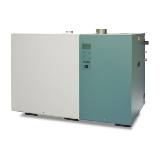
Page 6: Se Humidifier Models
50 lb/hr (23 kg/hr) to 1050 lb/hr (475 kg/hr). SETC humidifiers are packaged in five different cabinets depending upon capacity. See Figure 7: SE Indoor Dimensions on page 11 for dimensional information. Figure 2: SE Series Indoor Models 3 | SE Engineering Manual... - Page 7 (475 kg/hr). The SETC Outdoor humidifiers are packaged in four different cabinets depending upon capacity. See Figure 8: SETC Outdoor Dimensions on page 12 for dimensional information. SETC Outdoor 525-750 SETC Outdoor 100-175 SETC Outdoor 250-375 SETC Outdoor 1050 Figure 3: SE Series Outdoor Models SE Engineering Manual | 4...
- Page 8 The SETC model’s Total Controller provides a graphic LCD screen and keypad, accepts additional control signals, optional building management system connectivity (BACnet, Lonworks, Johnson N2, and Modbus), and optional Internet monitoring via Condair Online. See Table 1: SETC Features for a listing of the two control systems features.
-
Page 9: Se Humidifier Features
SE Humidifier Features The SETC humidifier includes many advanced features that sets it apart from other humidifiers. The following list outlines some of the SE series key features. Table 1: SETC Features General SETC SETC Outdoor High efficiency stainless steel heat exchangers... -
Page 10: Se Humidifier Components
SE Humidifier Components Figure 5: SETC Humidifier Components 7 | SE Engineering Manual... -
Page 11: Description Of Components
Description of Components Table 2: Humidifier Components Component Function of Component Actuator Opens and closes the control valve in proportion to demand for steam. Auxiliary Drain Outlet Drains water from tank in case of pump failure. Base Provides an integrated floor support for the humidifier. Clean Out Port(s) Provides access to clean scale from the tank and heat exchanger. -
Page 12: Se Outdoor Components
SE Outdoor Components Mounting Panel (External Disconnect) Steam Outlet Exhaust Fan Outdoor Cabinet Cabinet Thermostat Cabinet Drain (Drain Pan) Heater Outdoor Mounting Base (With integral drain Lifting Hook (4) pan) Pipe Chase (not visible) Figure 6: SETC Outdoor Components Table 3: SETC Outdoor Components Component Function of Component Cabinet Drain... -
Page 13: Se Humidifier Specifications & Dimensions
SE Humidifier Specifications and Dimensions Table 4: SETC Specifications Model Control Control Cond- Net/Full Required fill Required Electrical Valve Valve, ensate Weight line flow Drain Port lb (kg) gal (l) /min capacity kV (CV) Steam gal (l) /min Inlet, (BSP) Port (BSP) 125/180... - Page 14 Figure 7: SE Indoor Dimensions 11 | SE Engineering Manual...
- Page 15 Table 6: SETC Outdoor Specifications Model Net/Full Amps Power Max. Voltage Weight Disconnect lb (kg) Phase 267/423 0.65 Voltage (121/192) 0.65 355/599 0.65 Phase (161/272) 0.65 529/992 1.15 Hertz (240/450) 1.15 703/1384 1050 1.65 (318/628) Note: See Table 4: SETC Specifications and Table 5: SETC Capacities and Water Consumption on page 10 of SE Series Installation manual for remaining specifications ¾”...
-
Page 16: 14 Humidifier Specification Checklist
14 Humidifier Specification Checklist 15 Humidifier Load 15 Humidification Load Supply Line Losses Distributor Losses 17 Supply Steam Pressure 18 Humidifier Controls 18 Installation Location 19 Steam Distribution Method 19 SE Series Options and Accessories 24 Sample Specification 13 | SE Engineering Manual... - Page 17 Humidifier Specification Checklist The following checklist can be used to specify the SE Series Humidifier. A description of each selection is provided later on in this section. Humidifier Tag: _______________ Zone _______________ Humidifier Model ____________________________ Part No _______________ Humidifier Load ______________kg/hr =...
-
Page 18: Humidifier Load
Humidifier Load The SE Series humidifiers are available with capacities ranging from 50 to 1050 lb/hr (23 to 477 kg/hr). In addition to the available models, up to 10 humidifiers can be combined together to operate from one control signal for capacities of over 10,500 lb/hr (4,770 Kg/hr). The humidifier(s) selected must have a capacity equal to or greater than the load. - Page 19 Example 1: Supply Line Losses - SE 250 with 30 ft (9.15 m) x 3 in. (76 mm) steam line with one 90º elbow. 1 Obtain possible losses for 3 in line from Table 11. A = 0.24 kg/hr/m or 0.16 lb/hr/ft 2 Calculate the equivalent length of steam line using 3 in.
- Page 20 Supply Steam Pressure One of the unique features of the steam exchange humidifier is that its maximum output is affected by the steam supply pressure. Models are designated by the capacities at maximum supply pressure of 15 psi (1.034 Bar). An SETC 1050 will produce 1050 lb/hr (477 Kg/hr) of steam when supplied with 15 psi (1.034 Bar) steam.
-
Page 21: Humidifier Controls
Demand and Transducer On/Off Dry Contact 24 VAC The control signal type can be configured by Condair at the factory or can be user configured. For the SETC the configuration is done with the LCD and keypad. Installation Location Refer to the section on Location on page 29 for details about clearance requirements and information about optional stands and ceiling kits. -
Page 22: Steam Distribution Method
Steam Distribution Method Steam may be added to air in a supply air duct or air handler using Condair Steam Distributors or short absorption manifolds. Steam can also be added directly into a space by using remote mounted blower packs. Refer to the section Steam Distribution starting on page 41 for information about steam distribution methods and the steam lines used to connect the SE humidifier to steam distributors. - Page 23 Refer to the engineering manual for the particular manifold being used for more information. SE 50 Ceiling kit The Condair SE-050 ceiling mount model includes a ceiling mounting kit (part number 2520345) which allows the it to be ceiling mounted with zero clearance to the ceiling.
- Page 24 Signal? available for each available control configuration. (See Control Acceptance Configured at Factory on page 48) Condair e-Links / Links XPS / LINKS 2 Condair e-Links provides connectivity to BACnet, Lonworks, or Johnson N2 building management systems. A separate part number must be selected to specify the type of building management system.
- Page 25 Steam line adapters are used for connecting multiple steam lines into a single larger steam line. All adapters include a condensate drain to prevent build up of condensate. Condair offers a range of adapters suitable for combining up to 8 x 1 ¾ in. steam lines.
- Page 26 Large / Small Condensate Trap Condensate traps must be used to remove condensate that forms in steam distribution lines. Condair offers copper condensate traps to match its large and small steam hose. 1329634 – Steam Line Reducer 7/8 x 7/8 x 3/8...
-
Page 27: Sample Specification
Sample Specification PART 1 - GENERAL 1.1 Work Included: A. Condair SETC Series Steam Exchange Humidifier(s) as indicated on drawing(s) and as indicated on schedule(s). B. Complete and operable humidification system (which meets applicable building codes). C. Equipment start-up and project inspection by qualified factory trained representative. - Page 28 PART 2 - PRODUCTS STEAM EXCHANGE HUMIDIFIERS 2.1 The CONDAIR SETC steam exchange system uses all water types including, De-Ionized (DI), Reverse Osmosis (RO), potable and softened water. 2.2 Packaged unit, wall mounted, steam exchange humidifier operating with boiler steam pressures between 5 psi to 15 psi (0.34 to 1.03 bar), with output capacities up to 1050 lbs/hr...
- Page 29 L. Dual magnetic electronic float system, located outside of the boiling water to ensure accurate water level control and reduced maintenance. Cool fill water is to be supplied into the sensing chamber to keep the device cool. Systems using conductivity probes or floats located within hot reservoir water are not acceptable.
- Page 30 2. Operational Test: After electrical circuitry has been energized, start units to confirm proper unit operation. Remove malfunctioning units, replace with new units, and retest. 3. Test and adjust controls and safeties. Replace damaged and malfunctioning controls and equipment. 3.4 Training: A.
-
Page 31: Location
SETC Controls Condair Controls Control Location Control Wiring Staged Modulation Condair e-Links (Optional SETC) NOTE: The following sections provide an outline of the installation requirements. For detailed installation instructions refer to SE Series Installation and Operation Manual and to SE Outdoor Supplemental Installation and Spare Parts Manual . - Page 32 Clearance dimensions shown are for reference only and are the minimum required for maintenance of the humidifier. Consult local and national codes before final location and installation. Condair does not accept responsibility for installation code violations. 29 | SE Engineering Manual...
- Page 33 Figure 11: SE Indoor Installation Location / Clearance The SE series humidifiers are designed to be either floor mounted or stand mounted (stand optional). SE 50 ceiling models can also be ceiling mounted with the ceiling installation kit. Note: Condensate drain line must be sloped downward to boiler condensate return.
- Page 34 Figure 12: Optional SE Indoor Stand Ceiling Mounting (SE50 Only) Condair offers an optional ceiling mounting kit (part number 2520345) which allows the SE50 to be ceiling mounted with zero clearance to the ceiling. Follow the following guidelines for installation.
- Page 35 A drain line emptying into an open drain must be connected to the ceiling kit drain pan. Condair recommends a minimum 1/2 in. (13 mm) pipe with sufficient slope to ensure any water collected in the pan will drain from it.
- Page 36 Outdoor Location 0-100% As Close as 36 in. (91 cm) Min. (Non Possible to Steam Mount top clearance Condensing) Distributor HumidifierLevel (SE525 - 1050 only) 10 in. 30 in. (25 cm) 30 in. (76 cm) Min. (76 cm) Min. (SE525- Min.
- Page 37 Install so that ventilation louvers are not obstructed and cannot be blocked by accumulation of ice and snow. SETC Outdoor Curb The base of the SETC includes a drain pan with a pipe chase to route water, drain, boiler steam, boiler steam condensate, control wiring, and primary power wiring.
- Page 38 Plumbing 0.75 in. (19 mm). OD un-threaded drain outlet Connect with hose cuff and hose clamps. 1/2 in. NPT Use union to connect supply pipe to unit. Always install a water shut-off valve. Air gap required. 2 1/2 in. to 1 1/4 in. copper reducer is ideal.
- Page 39 Fill Valve Fill Connection 1/2 in. male NPT Drain Connection 0.75 in. (19 mm). OD un-threaded Freeze Insulate and heat trace Protection water supply line up to fill Valve valve if installed where freezing can occur. Pipe Chase Freeze Protection Valve Connection 1/2 in.
- Page 40 Freeze Protecting Water Supply Caution:. When installing the SETC Outdoor in condition where the temperature may drop below 32 ºF (0 ºC) always follow these guidelines to protect the water supply line from freezing. A frozen and burst water line can cause serious damage to property. ...
- Page 41 Boiler Steam and Boiler Condensate Return Note:. Damage to SE heat exchanger will occur if it is exposed to pressure above 20 psi (1.38 Bar). A safety relief valve must be installed to prevent the SE from being exposed to pressure in excess of 15 psi (1.03 Bar) when the SE is connected to a medium or high pressure boiler via a pressure reducing valve.
- Page 42 The port sizes of the control valve, boiler steam inlet port, and condensate drain port are given in Table 4: SETC Specifications on page 10. Follow the following guidelines for installation. All steam line connections must be installed in accordance with local codes. ...
- Page 43 Electrical Caution: All SE humidifiers operate on 230 VAC, single phase, 50 HZ power. Refer to specification label for power requirements. Figure 21: Primary Power Connections SE Engineering Manual | 40...
- Page 44 The best way to add steam into a conditioned environment is to add it in a supply air duct or an air handler. Condair offers both single steam distributors as well as short absorption steam distribution manifolds for adding air to ducts and air handlers (see Figure 22).
-
Page 45: Steam Lines & Condensate Returns
Material – The atmospheric steam line between the tank steam outlet and the distributor may be Condair steam hose, copper pipe, or stainless steel pipe or tube. Table 10 lists recommended materials and sizes for based on humidifier capacity. - Page 46 <4.5 ***Part Number 1328820 (1 3/4”) Note: * Condair offers adapters and reducers which can be used to convert from one size of steam line to another. Condensate Returns Condensate should not be routed to a sink used frequently by personnel. Route to a floor drain or equivalent.
- Page 47 Table 11: Maximum Recommended Length of Steam Line Unit Steam Output Steam Outlet and Maximum Possible Loss Possible Loss at Size Line Size Length Max. length lb/hr (kg/hr) Copper (SST) lb/hr/ft (kg/hr/m) lb/hr (kg/hr) (23) 1 1/2 (1 3/4) (11) 0.11 (0.16) (45)
- Page 48 Steam Line Routing SE Outdoor The Steam outlet(s) of the SETC Outdoor is from the back of the humidifier and unlike the indoor model does not require 12 in. (30 cm) of vertical steam run immediately after the humidifier. The steam line may be routed directly down or horizontally from the outlet. See Figure 26: SETC Outdoor Steam Outlet.
-
Page 49: Setc Controls
SETC Controls Controls are available from Condair as accessories or can be supplied by others. The following information is relevant to all controls, factory supplied or otherwise. The SETC humidifier can be operated with one or two modulating demand inputs; or one or two transducer inputs. -
Page 50: Condair Controls
Different models can accept different signals (see Table 13: Humidifier Control Configurations) Condair supplied controllers send a 0-10 VDC demand signal. This signal can be used as a control and in some models can also be used as a modulating high limit. These controls include: ... - Page 51 The outdoor temperature sensor is used to prevent condensation on windows or other surfaces that are adjacent to outdoor air. This sensor can be used in conjunction with the Condair digital on/off and modulating controllers. The sensor allows the controller to override the set point to prevent the humidifier from humidifying when condensation could be possible (see Figure 27).
-
Page 52: Control Location
Control Location The humidity controls, whether demand control or transducer, must be installed in a location which best represents the space that is being humidified. The preferred location for the humidity control is in the return air duct. The high limit duct sensor must be installed downstream of the steam distributor before any obstructions to laminar air flow. -
Page 53: Control Wiring
Control Wiring The SE humidifier control terminal strip is shown in Figure 29 along with a brief description of each of the inputs/outputs. The figure also shows the SETC remote relay board. For wiring use minimum of 18 AWG and keep as short as possible. Figure 29: SE Humidifier Control Terminal Strip SE Engineering Manual | 50... -
Page 54: Staged Modulation (Setc Only)
Staged Modulation Staged Modulation allows connection of up to 10 humidifiers (equivalent of 10,000 lb/hr) to one control signal. Each unit connected in a staged system is configured to operate within a fixed range of the total system demand. Example, a slave unit configured to operate between 20 and 30% demand will output 0% when total system demand is less than 20% and 100% when demand is 30% or greater. -
Page 55: Condair E-Links (Optional Setc Only)
Condair e-Links (Optional SETC) Condair e-LINKS is an option that can be integrated with the SETC. It allows a Building Management System to monitor and / or control the humidifier. See Condair publication 2531037 – Links GSTC/SETC Installation and Operation Manual for detailed information about Condair LINKS and its operation and configuration. -
Page 56: Variable Definition
Variable Definition Table 3. Variable Definitions R=Read Description LonWorks SNVT Variable Name W=Write Reads %RH in space or %demand to nvoRHDem1_x humidifier. (0%-100%) Choice SNVT_lev_percent Analog Value determined by nviInputType_x. Reads setpoint for relative humidity in nvoSet1_x SNVT_lev_percent space. (0%-100%) Analog Value Reads duct %RH or secondary space %RH, or secondary %demand to... - Page 57 R=Read Variable Name Description LonWorks SNVT W=Write Reads setpoint for relative humidity in nvoSet1_x SNVT_lev_percent space. (0%-100%) Analog Value Reads duct %RH or secondary space %RH, or secondary %demand to humidifier. (0%-100%) nvoRHDem2_x SNVT_lev_percent Choice determined by nviInputType_x. Analog Value Dip Switch 4/5 on humidifier’s logic board must be ON.
- Page 58 Table 4. Humidifier Variable Addresses Unit #1 GSTC/SETC e-LINKS Variable Mapping Default BACnet/IP Address: 192.168.10.11; Subnet: 255.255.255.0 Default BACnet/MSTP Address: 79 Default Johnson N2 Address: 175 Default unless otherwise requires at time of order. Unit #1 BACnet Lonworks Variable Name Type Instance SNVT SNVT # NV Index Element Type Instance...
- Page 59 Warranty Condair AG. and/or Nortec Humidity Ltd. (hereinafter collectively referred to as THE COMPANY), warrant for a period of two years after installation or 30 months from manufacturer’s ship date, whichever date is earlier, that THE COMPANY’s manufactured and assembled products, not otherwise expressly warranted, are free from defects in material and workmanship.
- Page 60 EUROPE, ASIA, SOUTH AMERICA Condair AG Talstrasse 35-37 8808 Pfäffikon, Switzerland NORTH AMERICA Nortec Humidity Ltd. 2740 Fenton Road Ottawa, Ontario K1T 3T7 WEBSITE: www.condair.com Manufactured By: Nortec Humidity Ltd. 2740 Fenton Road Ottawa, Ontario Canada K1T 3T7 Tel: +1 613 822 0335 Fax: +1 613 822 7964 Email: nortec@humidity.com...
Need help?
Do you have a question about the SE Series and is the answer not in the manual?
Questions and answers