Table of Contents
Advertisement
Quick Links
Advertisement
Table of Contents

Related Manuals for N-Tron 600 Series


Summary of Contents for N-Tron 600 Series
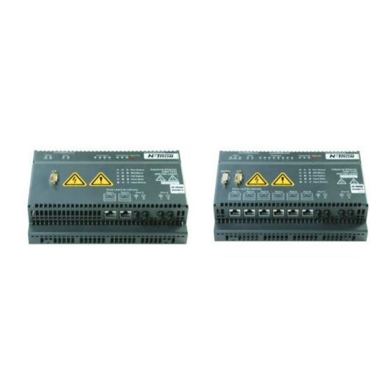
- Page 1 600 Series Industrial Ethernet Switches Hardware Installation Guide 12/15/05...
- Page 2 Industrial Ethernet Switch Installation Guide 604MFX-ST 604MFXE-ST-15 604MFXE-ST-40 604MFXE-ST-80 608MFX-ST 608MFXE-ST-15 608MFXE-ST-40 608MFXE-ST-80 12/15/05...
- Page 3 The information contained in this document is subject to change without notice. N-TRON Corp. makes no warranty of any kind with regard to this material, including, but not limited to, the implied warranties of merchantability or fitness for a particular purpose.
-
Page 4: Safety Warnings
Safety Warnings ELECTRICAL SAFETY WARNING: Disconnect the power cable before removing the enclosure top. WARNING: Do not operate the unit with the top cover removed. WARNING: Do not work on equipment or cables during periods of lightning activity. WARNING: Do not perform any services on the unit unless qualified to do so. - Page 5 CLI (Command Line Interface – Serial Port), Telnet, and/or Web based browsers. The 600 Series Switches can also serve as a redundancy managers, detect faults in ring topologies and allow high-speed ring network healing, thus providing media redundancy for mission critical control applications.
-
Page 6: Package Contents
PACKAGE CONTENTS Please make sure the Ethernet Switch package contains the following items: 1. 600 Series Ethernet Switch 2. This Installation Guide Contact your carrier if any items are damaged. INSTALLATION Read the following warning before beginning the installation: WARNING The FXE units contain a class 1 laser. - Page 7 3” of clearance for fiber optic cable bend radius, and 2 inches for TX cables and power connections. Please note the 600 Series units must be installed in the vertical orientation for cooling purposes. In this orientation, the power connector is at the top of the unit, and the signal cables exit from the bottom of the unit.
-
Page 8: Applying Power
For redundant power operation, L1 and L2 terminals must be connected to separate DC Voltage sources. Use wire sizes 14-28 gauge. Recommended 24V DC Power Supplies, similar to: 100VAC/240VAC: N-Tron’s NTPS-24-1.3, DC 24V/1.3A, Operating temp range -10°C to +60°C 12/15/05... - Page 9 MANAGER 608M FX 608M FX FIBER OPTIC PAIR 608M FX FIBER OPTIC PAIR CAT5 CAT5 CAT5 CAT5 CAT5 CAT5 Additional N-TRON DRIVE LAPTOP 405TX Ports (UP TO 6 COPPER PORTS CONNECTED TO EACH 608MFX) 608MFX RING TOPOLOGY Figure 1 12/15/05...
- Page 10 HP-MDIX auto cable detect feature. For 10/100BaseTX operation, the 600 Series Switch will sense & adapt accordingly. A maximum number of 50 600 Series switches can be connected in a single ring. CONNECTING MULTIPLE RINGS (608MFX Only) For multiple rings, the connection between two network segments is made on two separate paths.
- Page 11 608MFX FIBER OPTIC PAIR RING MANAGER ITP Cable 608M FX 608MFX FIBER OPTIC PAIR 608M FX FIBER OPTIC PAIR Standby Standby M aste r Slave Cat5E Cat5E 608M FX 608MFX FIBER OPTIC PAIR 608M FX FIBER OPTIC PAIR 608MFX FIBER OPTIC PAIR RING MANAGER 608MFX Network Segment Redundancy...
- Page 12 The ring is operating free of errors, as monitored by the redundancy manager. Note: One (and only one) 600 Series Switch must operate as the redundancy manager in each ring. The 608MFX is not operating in the redundancy manager mode.
- Page 13 The display Mode is indicated by the LED pair labeled “Display Mode”, and the state is given by the legend on the front of the 600 Series Switch. To transition between these Display Modes, the Select/Set button must be pressed briefly (similar to left mouse click).
- Page 14 Display Mode LEDs begin to flash. If you then continue to press the button for a further two seconds, the switch is reset. When the 600 series switch is reset, all the settings return to their defaults (as set in the factory). This...
- Page 15 IEEE 802.1Q, VLAN The 600 Series switches do not support VLAN tags according to IEEE 802.1Q. Users must configure their networks so that no VLAN packets are sent.
- Page 16 Serial Interface The 604/608MFX provides an EIA-232 interface accessed via a 9 pin male connector (labeled V24 on the unit). This is used to access the Command Line Interpreter (CLI). Functions include setting the IP address, and other parameters (see Network Management Users guide). The pin-outs are shown below: Pin 1 DSR Pin 6...
- Page 17 Serial Cable Connect the serial COM port of your PC and the 600 Series Switch using a normal null modem cable (or a straight through cable with a null modem adapter). You will require a cable with a 9-pin or 25-pin sub-D female connector for the PC end, and a 9-pin female sub-D connector for the 608MFX end.
-
Page 18: Troubleshooting
Operation, 62.5/125 m @ 1300nm for 100 Mbit FX Operation. 8. Verify TX port #7 is connected to RX port #8 (and vice versa). 9. Verify that only one 600 series switch is in RM (redundancy manager) mode. FCC STATEMENT This product complies with Part 15 of the FCC-A Rules. -
Page 19: Key Specifications
KEY SPECIFICATIONS Physical Height: 5.5" (13.65 cm) Width: 8.55" (21.70 cm) Depth: 2.75" (6.90 cm) Weight: 3.08 lbs (1.4 kg) Electrical Input Voltage: 18-32 VDC (Redundant inputs) Input Current: 1.0A @ 24V Power Consumption: 24 Watts @24V Environmental 0°C to 60°C Operating Temperature: -40°C to 80°C Storage Temperature:... - Page 20 19” Rack Mount Kit SDP1 Din Rail Power Supply 111-220VAC input 24VDC@1.3A Warranty One Year Parts and Labor Contact/Support Information N-TRON Corp 820 S. University Blvd., Suite 4E, Mobile, AL 36609 TEL: (251) 342-2164 FAX: (251) 342-6353 Website: www.n-tron.com E-mail: support@n-tron.com...
-
Page 21: N-Tron Limited Warranty
N-TRON Limited Warranty N-TRON, Corp. warrants to the end user that this hardware product will be free from defects in workmanship and materials, under normal use and service, for the applicable warranty period from the data of purchase from N-TRON or its authorized reseller. - Page 22 CONNECTION WITH THE SALE, INSTALLATION, MAINTENANCE, USE, PERFORMANCE, FAILURE, OR INTERRUPTION OF ITS PRODUCTS, EVEN IF N-TRON OR ITS AUTHORIZED RESELLER HAS BEEN ADVISED OF THE POSSIBILITY OF SUCH DAMAGES, AND LIMITS ITS LIABILITY TO REPAIR, REPLACEMENT, OR REFUND OF THE PURCHASE PRICE PAID, AT N-TRON'S OPTION.
Need help?
Do you have a question about the 600 Series and is the answer not in the manual?
Questions and answers