
Subscribe to Our Youtube Channel
Related Manuals for N-Tron 105M12


Summary of Contents for N-Tron 105M12
-
Page 1: Installation Guide
105M12 and 108M12 Industrial Ethernet Switches Installation Guide (Revised 2010-11-15) - Page 2 105M12 & 108M12 Industrial Ethernet Switches Installation Guide (Revised 2010-11-15)
- Page 3 In no event shall N-TRON Corp. be liable for any incidental, special, indirect or consequential damages whatsoever included but not limited to lost profits arising out of errors or omissions in this manual or the information contained herein.
-
Page 4: Safety Warnings
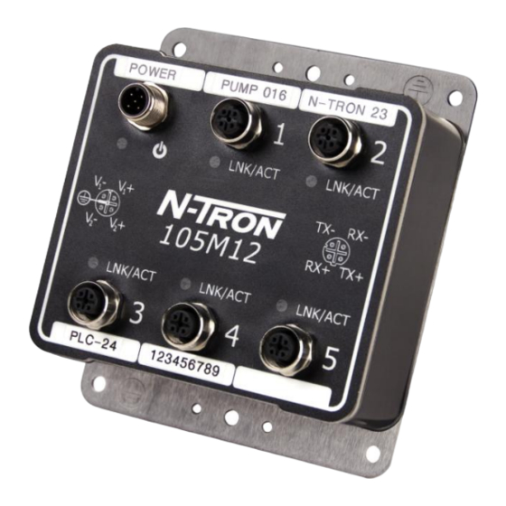
SAFETY WARNINGS ELECTRICAL SAFETY WARNING: Disconnect the power cable before removing the end plates. WARNING: Do not operate the unit with the end plates removed. WARNING: Properly ground the unit before connecting anything else to the unit. Units not properly grounded may result in a safety risk and could be hazardous and may void the warranty. - Page 5 105M12 Industrial Ethernet Switch The 105M12 is an unmanaged industrial Ethernet switch providing five Fast Ethernet copper ports in an IP65/IP67 rated enclosure for protection against temporary immersion in water. The switch provides Category-5 compliant 10/100BaseTX connections with IP65/67 rated M12 D-code connectors for high performance network design, and hub/repeater upgrades.
-
Page 6: Ingress Protection Ip67
Protected against long periods of immersion under pressure. The 105M12 and 108M12 Industrial Ethernet Switches are fully protected against dust and will remain sealed when immersed in water to a depth of 1 meter for 1 hour when all the ports are properly mated or sealed. -
Page 7: Installation
WARNING Never install or work on electrical equipment or cabling during periods of lightning activity. BULKHEAD MOUNTING The following are the mechanical dimensions and drill hole placements to consider when mounting the 105M12 and 108M12 Industrial Ethernet Switches: (Revised 2010-11-15) -
Page 8: Front Panel
FRONT PANEL LNK/ACT Link/Activity LED M12 D-Coded Female Ports All ports are Auto sensing 10/100BaseTX Connections M12 A-Coded Male Port Redundant Power Input (10-30VDC) Green LED lights when Power is connected LED’s: The table below describes the operating modes: Color Description Power is Applied. -
Page 9: Applying Power
V must be connected to separate DC Voltage sources. The power cord should be limited to less than 10 meters in order to ensure optimum performance. Recommended 24V DC Power Supplies, similar to: 100VAC/240VAC: N-Tron NTPS-24-1.3, DC 24V/1.3A (Revised 2010-11-15) -
Page 10: Connecting The Unit
N-TRON 105M12 AND 108M12 GROUNDING TECHNIQUES Drain wire with lug connecting switch chassis to known grounding point. CONNECTING THE UNIT For 10Base-T ports, plug a Category 3 (or greater) twisted pair cable into the M12 connector. For 100Base-T ports, plug a Category 5 (or greater) twisted pair cable into the M12 connector. Connect the other end to the far end station. -
Page 11: Fcc Statement
FCC STATEMENT This product complies with Part 15 of the FCC-A Rules. Operation is subject to the following conditions: (1) This device may not cause harmful interference (2) This device must accept any interference received, including interference that may cause undesired operation. - Page 12 KEY SPECIFICATIONS – 105M12 Physical Height: 5.00” (12.7cm) 4.32” (10.97cm) Width: Depth: 1.8” (4.57cm) Weight: 1.8 lbs. (0.81kg) DIN Rail: 35 mm (Optional) Electrical Input Voltage: 10-30 VDC (Regulated) Input Current: 215 mA max. @ 24VDC (Steady State) Inrush Current: 7.8 Amp/0.7ms max.
- Page 13 KEY SPECIFICATIONS – 108M12 Physical Height: 6.62” (16.81cm) Width: 6.62” (16.81cm) Depth: 1.8” (4.57cm) Weight: 3.3 lbs. (1.49kg) DIN Rail 35 mm (Optional) Electrical Input Voltage: 10-30 VDC (Regulated) -HV Option: 10-60 VDC (Regulated) Input Current: 250 mA max. @ 24VDC (Steady State) Inrush Current: 8.1 Amp/0.7ms max.
- Page 14 ICES-003 – Class A EMS: EN61000-6-2 EN61000-4-2 (ESD) EN61000-4-3 (RS) EN61000-4-4 (EFT) EN61000-4-5 (Surge) EN61000-4-6 (Conducted Disturbances) GOST-R Certified. Warranty: Effective January 1, 2008, all N-TRON products carry a 3 year limited warranty from the date of purchase. (Revised 2010-11-15)
- Page 15 Responsibility for loss or damage does not transfer to N-TRON until the returned item is received by N-TRON. The repaired or replaced item will be shipped to the customer, at N-TRON’s expense, not later than thirty (30) days after N-TRON receives the product.
Need help?
Do you have a question about the 105M12 and is the answer not in the manual?
Questions and answers