Sign In
Upload
Download
Table of Contents
Contents
Add to my manuals
Delete from my manuals
Share
URL of this page:
HTML Link:
Bookmark this page
Add
Manual will be automatically added to "My Manuals"
Print this page
×
Bookmark added
×
Added to my manuals
Manuals
Brands
N-Tron Manuals
Switch
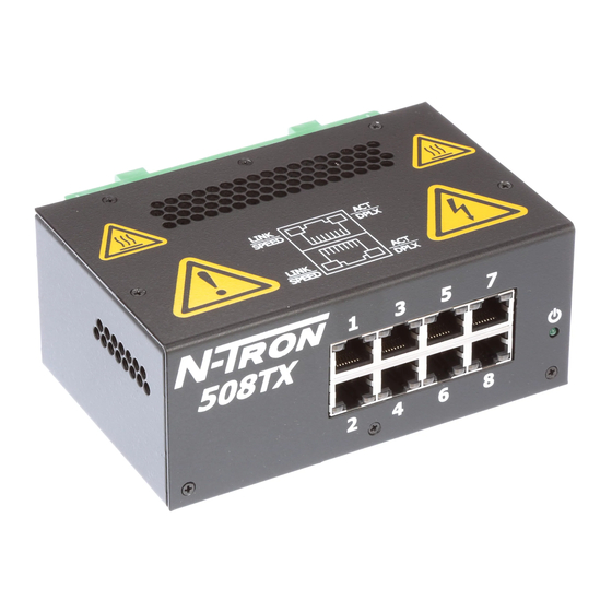
508TX
Installation manual
N-Tron 508TX Installation Manual
500 series industrial ethernet switches
Hide thumbs
Also See for 508TX
:
Specifications
(2 pages)
1
Table Of Contents
2
3
4
5
6
7
8
9
10
11
12
13
14
15
16
17
18
19
20
21
22
23
24
25
26
27
28
29
30
31
32
33
34
35
36
37
38
39
40
41
42
43
44
45
46
47
48
49
50
51
52
53
54
55
56
57
58
59
60
61
62
63
64
65
66
67
68
69
70
71
page
of
71
Go
/
71
Contents
Table of Contents
Troubleshooting
Bookmarks
Table of Contents
Industrial Ethernet
Table of Contents
Applicability
Safety Warnings
Overview: 500 Series Industrial Ethernet Switches
Key Features
Installation
Panel and Rack Mounting
Front Panel
Applying Power (Side View)
N-Tron Switch Grounding Techniques
RJ45 Connector Crimp Specifications
Connecting the Unit
Serial Interface
Troubleshooting
FCC Statement
Command Line Interpreter
Logging in (Password Protection)
CLI Tree of Menus
CLI Menus and Commands
Home Menu
Top Level Info
System Menu
N-View TM Menu
Aging Menu
System Info
Restoring Defaults
User Password
Switch Menu
Port Mirroring
MAC Based Trunking
Qos
Vlan
Tagged VLAN
Port VLAN
IGMP Snooping
Filters
Ports
500 Series Stacked Switches IGMP Multicast Limitations
With Quality of Service (QOS) DISABLED, as in Factory Defaults out of Box
With Quality of Service (QOS) ENABLED, Which Would Have to be Manually Configured
Key Specifications (508TX)
Damp Heat
IEC60068-2-30 (Test Db)
GOST-R Certified
Key Specifications (508FX2/FXE2)
Key Specifications (509FX/FXE)
GOST-R Certified
Key Specifications (516TX)
Damp Heat
IEC60068-2-30 (Test Db)
GOST-R Certified
Key Specifications (517FX/FXE)
Damp Heat: IEC60068-2-30 (Test Db)
GOST-R Certified
Key Specifications (524TX)
Damp Heat: IEC60068-2-30 (Test Db)
GOST-R Certified
Key Specifications (526FX2/FXE2)
Advertisement
Quick Links
1
Industrial Ethernet
2
Installation
3
Connecting the Unit
4
Troubleshooting
5
Logging in (Password Protection)
Download this manual
500 Series
Industrial
Ethernet
Switches
Installation
Guide
(Revised 2013-06-21)
1
Table of
Contents
Previous
Page
Next
Page
1
2
3
4
5
Advertisement
Table of Contents
Need help?
Do you have a question about the 508TX and is the answer not in the manual?
Ask a question
Questions and answers
Related Manuals for N-Tron 508TX
Switch N-Tron 508TX-A Specifications
Industrial ethernet switch (2 pages)
Switch N-Tron 500 Series Installation Manual
Industrial ethernet switches (71 pages)
Switch N-Tron 509FX Specification Sheet
N-tron industrial ethernet switch specification sheet (2 pages)
Switch N-Tron 524TX-A Specifications
Twenty-four port industrial ethernet switch (2 pages)
Switch N-Tron 526FX2-A Specification Sheet
Industrial ethernet switch (2 pages)
Switch N-Tron 524TX Installation Manual
500 series industrial ethernet switches (71 pages)
Switch N-Tron 702-W Features
N-tron hub/switch product manual (2 pages)
Switch N-Tron 516TX Installation Manual
500 series industrial ethernet switches (71 pages)
Switch N-Tron 509FX-N S Series Installation Manual
Industrial ethernet switches (71 pages)
Switch N-Tron 714FX6 User Manual & Installation Manual
Managed industrial ethernet switch (158 pages)
Switch N-Tron 7026 Series User Manual & Installation Manual
Managed industrial ethernet switch (169 pages)
Switch N-Tron 708TX User Manual & Installation Manual
700 series managed industrial ethernet switch (154 pages)
Switch N-Tron 900 Installation & User Manual
900 series industrial ethernet switch (18 pages)
Switch N-Tron NT24k Rack Mount User Manual
Managed industrial ethernet switch (132 pages)
Switch N-Tron 7018TX User Manual & Installation Manual
7018 series managed industrial ethernet switch (157 pages)
Switch N-Tron 302MC-XX Installation Manual
Media converter & industrial ethernet switches (17 pages)
This manual is also suitable for:
516tx
524tx
500 series
508tx-n
516tx-n
524tx-n
...
Show all
508fx2-n-xx-s
509fx-n-xx-s
517fx-n-xx-s
526fx2-n-xx-s
508fxe2-n-xx-yy
509fxe-n-xx-yy
517fxe-n-xx-yy
526fxe2-n-xx-yy
508fx2
508fxe2
509fx
509fxe
517fx
517fxe
526fx2
526fxe2
Table of Contents
Print
Rename the bookmark
Delete bookmark?
Delete from my manuals?
Login
Sign In
OR
Sign in with Facebook
Sign in with Google
Upload manual
Upload from disk
Upload from URL


Need help?
Do you have a question about the 508TX and is the answer not in the manual?
Questions and answers