Table of Contents
Advertisement
Advertisement
Table of Contents

Subscribe to Our Youtube Channel
Summary of Contents for N-Tron 405FX-SC
- Page 1 400 Series Industrial Ethernet Switches Installation Guide (Revised 2010-11-15)
- Page 2 Industrial Ethernet Switch Installation Guide 405TX 405FX-SC 405FX-ST 405FXE-SC-YY 405FXE-ST-YY Where: YY = -15, -40, or -80 (Revised 2010-11-15)
- Page 3 In no event shall N-TRON Corp. be liable for any incidental, special, indirect or consequential damages whatsoever included but not limited to lost profits arising out of errors or omissions in this manual or the information contained herein.
-
Page 4: Electrical Safety
Safety Warnings ELECTRICAL SAFETY WARNING: Do not disconnect while circuit is live, unless area is known to be non-hazardous. WARNING: Disconnect the power cable before removing the enclosure top. WARNING: Do not operate the unit with the top cover removed. WARNING: Properly ground the unit before connecting anything else to the unit. - Page 5 2 Kilometers of 100 Mb communications without the use of repeaters. The 405FXE is a 5 port unmanaged switch that is similar to the 405FX, but with extended range. The N- TRON 405FXE utilizes a singlemode fiber transceiver that is capable of 15 Kilometers of 100 Mb communications.
-
Page 6: Package Contents
PACKAGE CONTENTS Please make sure the Ethernet Switch package contains the following items: 1. 405FX/405FXE/405TX Ethernet Switch 2. This Installation Guide Contact your carrier if any items are damaged. INSTALLATION Read the following warning before beginning the installation: WARNING The 405FXE unit contains a Class 1 Laser. Do not stare into the laser beam (fiber optic connector) when installing or operating the product. - Page 7 Ports Counter page to remotely monitor each connected port. You may find it helpful to Copy [Alt]+[PrintScreen] the Port Counter information for each port and Paste [Control]+[V] into a Windows document for further review. Please consult your N-View OPC Server Manual for additional information. (Revised 2010-11-15) http://www.n-tron.com/html/opc.html ). Once N-ViewOPC is...
- Page 8 Optional Mounting With the exception of the 524TX and 526FX2, all N-Tron™ products are designed to be mounted on industry standard 35mm DIN-Rail. However, DIN-Rail mounting may not be suitable for all applications.
-
Page 9: Front Panel
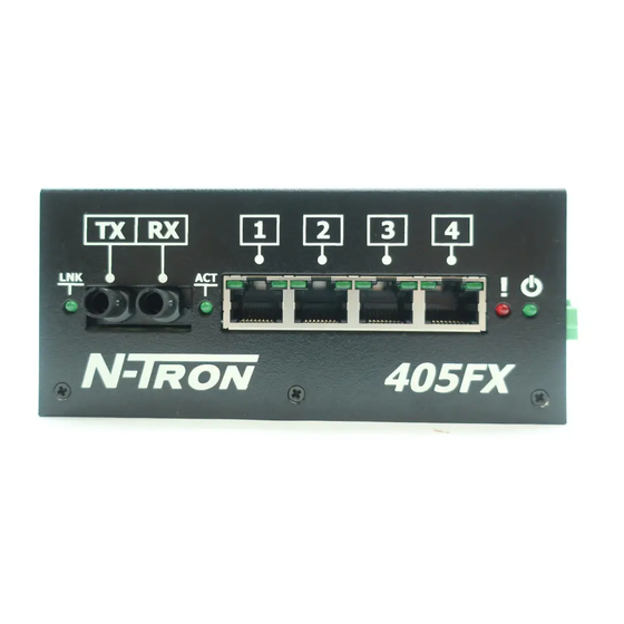
FRONT PANEL From Left to Right: Link LED for Fiber Optic Port (405FX/FXE only) Fiber Optic Transmit Port (405FX/FXE Only) Fiber Optic Receive Port (405FX/FXE Only) Activity LED for Fiber Optic Port (405FX/FXE only) RJ45 Crossover Uplink Port (405TX Only) RJ45 Ports Auto sensing 10/100BaseT Connections Red LED indicates controller error... - Page 10 Note: Only 1 plug is required to be connected to power input for minimal operation. For redundant power operation, V and V 16-28 gauge. Recommended 24V DC Power Supplies, similar to 100VAC/240VAC: N-Tron’s NTPS-24-1.3, DC 24V/1.3A (Revised 2010-11-15) Description Power is OFF Controller HW Error No Errors. Normal...
- Page 11 (i.e. CE) are obtained when the N-Tron switch chassis is connected to earth ground via a drain wire. Some N-Tron switches have metal din-rail brackets that can ground the switch if the din-rail is grounded. In some cases, N-Tron switches with metal brackets can be supplied with optional plastic brackets if isolation is required.
-
Page 12: Rj45 Connector Crimp Specifications
RJ45 CONNECTOR CRIMP SPECIFICATIONS Please reference the illustration below for your Cat5 cable specifications: (Revised 2010-11-15) -
Page 13: Connecting The Unit
For Switch to Switch or Switch to Repeater connections, use the X-port and a standard Category 5 cable. To connect any other port (other than the X-Port) to another Switch or Repeater, use a standard Category 5 crossover cable. -
Page 14: Key Specifications
KEY SPECIFICATIONS Physical Height: 2.13" (5.41 cm) Width: 5.00" (12.70 cm) Depth: 3.00" (7.62 cm) Weight: ~ 1.2 lbs. (0.6 kg) (Note: can be mounted horizontally or vertically) Electrical Input Voltage: 10-30 VDC (Regulated) Input Current: 220mA max. @ 24VDC (Steady State) Inrush Current: 14.0Amp/0.9ms max. - Page 15 EMI: EN55022 – Class A FCC Part 15 Class A EMS: EN55024:1998 EN61000-4-2:1995 EN61000-4-3:1997 EN61000-4-4:1995 EN61000-4-5:1995 EN61000-4-6:1996 GOST-R Certified. Warranty: Effective January 1, 2008, all N-TRON products carry a 3 year limited warranty from the date of purchase. (Revised 2010-11-15)
- Page 16 Responsibility for loss or damage does not transfer to N-TRON until the returned item is received by N-TRON. The repaired or replaced item will be shipped to the customer, at N-TRON’s expense, not later than thirty (30) days after N-TRON receives the product.


Need help?
Do you have a question about the 405FX-SC and is the answer not in the manual?
Questions and answers