
Related Manuals for N-Tron 308FX2


Summary of Contents for N-Tron 308FX2
- Page 1 308FX2, 309FX, 316TX, 317FX Industrial Ethernet Switches User Manual & Installation Guide (Revised 2010-7-30)
-
Page 2: Table Of Contents
Table of Contents Applicability: ..............................3 Safety Warnings ..............................4 Overview: 308FX2/309FX/316TX/317FX Industrial Ethernet Switches............8 Key Features............................... 9 Installation ................................9 Panel and Rack Mounting ..........................10 Front Panel ............................... 11 Applying Power (Side View) ........................... 12 N-Tron Switch Grounding Techniques ......................13 RJ45 Connector Crimp Specifications ...................... -
Page 3: Applicability
Applicability: This guide is applicable to Firmware Version 1 of the following products: 308FX2-N-XX 308FXE2-N-XX-YY 309FX-N-XX 309FXE-N-XX-YY 316TX-N 317FX-N-XX 317FXE-N-XX-YY Where: N = N for N-View = Blank Otherwise = ST or SC and YY = -15, -40, -80 Note: The firmware version can be seen on the power up banner on the serial console for any of these products. -
Page 4: Safety Warnings
In no event shall N-TRON Corp. be liable for any incidental, special, indirect or consequential damages whatsoever included but not limited to lost profits arising out of errors or omissions in this manual or the information contained herein. - Page 5 ENVIRONMENTAL SAFETY WARNING: Disconnect the power and allow to cool 5 minutes before touching. ELECTRICAL SAFETY WARNING: Disconnect the power cable before removing the enclosure top. WARNING: Do not operate the unit with the top cover removed. WARNING: Properly ground the unit before connecting anything else to the unit. Units not properly grounded may result in a safety risk and could be hazardous and may void the warranty.
- Page 6 (Revised 2010-7-30)
- Page 7 ATEX Installation Requirements 1. The conductor size of the phase conductor must be in the range of 0.05-2.08 mm2. 2. Field wiring must be suitable for a minimum of 110°C. 3. Ethernet Switches are intended for mounting in an IP54 enclosure in a pollution degree 2 environ ment.
-
Page 8: Overview: 308Fx2/309Fx/316Tx/317Fx Industrial Ethernet Switches
10/100 Mb and half/full duplex communications, or the user can configure these parameters. The 308FX2 is an affordable 8 port switch that has 6 copper ports plus two additional multimode fiber optic up-link ports. The two fiber links are capable of 2 Kilometers of 100 Mb communications without the use of repeaters.The 308FXE2 is similar to the 308FX2, but is populated with singlemode extended... -
Page 9: Key Features
Contact your carrier if any items are damaged. Installation Read the following warning before beginning the installation: WARNING The 308FX2/309/316/317 FXE-40 and FXE-80 units contain a class 1 laser. Do not stare into the laser beam (fiber optic connector) when installing or operating the product. (Revised 2010-7-30) -
Page 10: Panel And Rack Mounting
Our 900 Panel Mount Assembly (P/N: 900-PM) may be used to securely mount our 308FX2/309/316/317 products to a panel or other flat surface; Our Universal Rack Mount Kit (P/N: URMK) may be used to mount our products to standard 19" racks... -
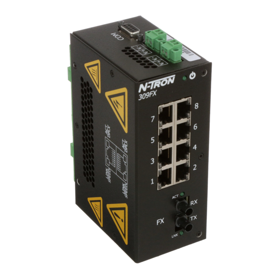
Page 11: Front Panel
Front Panel From Top to Bottom and Left to Right: Green LED lights when Power is connected RJ45 Ports Auto sensing 10/100 BaseTX Connections Link LED for Fiber Optic Port (only FX/FXE models) Activity LED for Fiber Optic Port (only FX/FXE models) 100MB/s Fiber Optic RX Port (only FX/FXE models) 100MB/s Fiber Optic TX Port (only FX/FXE models) NOTE: Each RJ45 data port has two LED‟s located at the top or bottom of each connector. -
Page 12: Applying Power (Side View)
DC Voltage sources. Use wire sizes 16-28 gauge. The power cord should be limited to less than 10 meters in order to ensure optimum performance. Recommended 24V DC Power Supplies, similar to 100VAC/240VAC: N-Tron‟s NTPS-24-1.3, DC 24V/1.3A. (Revised 2010-7-30) -
Page 13: N-Tron Switch Grounding Techniques
(i.e. CE) are obtained when the N-Tron switch chassis is connected to earth ground via a drain wire. Some N-Tron switches have metal din-rail brackets that can ground the switch if the din-rail is grounded. In some cases, N-Tron switches with metal brackets can be supplied with optional plastic brackets if isolation is required. -
Page 14: Rj45 Connector Crimp Specifications
Note: For units which have the N-View Option (-N), you can validate that all ports are working correctly by installing the N-View OPC Server software. The software is freely distributed on the ProductCD and our website (http://www.n-tron.com/pdf/nview_opc_manual.pdf ). Once the software is installed, you should view the Ports Counter page to remotely monitor each connected port. -
Page 15: Serial Interface
Serial Interface 308FX2/309/316/317 switches provide an EIA-232 interface accessed via a 9 pin female connector (labeled „COM‟ on the unit). This is used to access the Command Line Interpreter (CLI). The pin-outs are shown below: Pin 1 Pin 6 TXD Pin 2... - Page 16 5. Verify that cabling is Category 5E or greater for 100Mbit Operation. 6. For FX/FXE models, verify TX is connected to far end RX and vice versa. Also insure the connecting partner is 100Mb/s IEEE 100BaseFX compliant. Note: the 308FX2/309/316/317 FX/FXE switches do not support the 10BaseFL standard.
-
Page 17: Command Line Interpreter
Ethernet switch using a command line interpreter. These functions may be accessed using the serial port (marked COM). To access the Command Line Interpreter (CLI), connect a PC serial port to the 308FX2/309/316/317 V24 serial port and use HyperTerminal or equivalent. -
Page 18: Logging In (Password Protection)
Access using the CLI is password-protected. You can log in as administrator to read and modify the 308FX2/309/316/317 switch parameters. Note: The admin password is admin. On a 308FX2 switch, you must first press <Escape> to access the Management Console Function. enter username „admin’ and then press <Enter>. -
Page 19: Cli Tree Of Menus
(Force half duplex for each port) full (Force full duplex for each port) crossover (Force crossover connection for each port) ‘filters’ are on 308FX2 only: filters (Select traffic filter(s)) info (Get info on Filters) dis_nring (Disable filters for N-Ring) (or „en_nring‟... -
Page 20: Cli Menus And Commands
Top level info includes Model Number, Firmware version, MAC Address, and whether or not the N-View function is enabled. Example of the (top level) info screen: CLI>info N-TRON Industrial Ethernet Switch - Model Number: 308FX2-N. N-Tron firmware version : 1.01 (03) Copyright (c) 2010 N-TRON MAC ADDRESS: 00-07-AF-12-89-12 N-View is ENABLED. -
Page 21: System Menu
Rate for generation of MIB information frames is ~6.4 seconds. The FX Port is mapped to port 9 on the 309, and as port 17 on the 317. On the 308FX2, ports 7 and 8 are FX ports. Example of the N-View info screen: CLI\SYSTEM\N-VIEW>info... -
Page 22: System Info
Select traffic filter(s) ports Reconfigure Individual Port Parameters Filters On the 308FX2 only, filters are provided and enabled in defaults to keep ring control frames only on the ring ports. en_nring, or N-Ring filter 308FX2 ONLY. dis_nring Ports 7 and 8 are ring ports. -
Page 23: Ports
(We have seen a case where the wiring was cat3 and the devices autonegotiated to 100/full, but the wiring would not support it.) On the 308FX2, 309, 316, or 317, one can autonegotiate, or one can force to any of 4 modes: 100 full, 100 half, 10 full, or 10 half. - Page 24 basically functional but not ideal. The unit at 10 full transmits without checking for busy and you get more collisions. Also, the 10/full unit does not back off or retransmit based on the collision domain. The same problem happens with one unit forced to 100/full and the other autonegotiating. The autonegotiating unit goes into 100/half.
- Page 25 Example of the Ports half (duplex) screen: CLI\SWITCH\PORTS>half Enter forced Half Duplex ports> Use commas to separate port numbers. (Example: '3,6,12,14<enter>'.) Enter Port Numbers (or ESC to exit):5 CLI\SWITCH\PORTS> Example of the Ports crossover screen: CLI\SWITCH\PORTS>crossover Enter forced crossover ports> Use commas to separate port numbers.
-
Page 26: Key Specifications (308Fx2/Fxe2)
Key Specifications (308FX2/FXE2) Switch Properties Number of MAC Addresses 4,000 Aging Time Programmable Latency Min. 2.2 s Backplane Speed 2.6Gb/s Switching Method Store & Forward Physical Height: 2.3" Width: 5.9" Depth: 3.8" Weight: 1.7 lbs Din-Rail: 35mm Electrical Redundant Input Voltage:... - Page 27 IEEE 1613 (V.S.4 150 mm/s) IEC60068-2-6 (Test F Cold: IEC60068-2-1 Dry Heat: IEC60068-2-2 Damp Heat: IEC60068-2-30 (Test D GOST-R Certified. Warranty: Effective January 1, 2008, all N-TRON products carry a 3 year limited warranty from the date of purchase. (Revised 2010-7-30)
-
Page 28: Key Specifications (309Fx/Fxe)
Key Specifications (309FX/FXE) Switch Properties Number of MAC Addresses 4,000 Aging Time Programmable Latency Min. 2.2 s Backplane Speed 2.6Gb/s Switching Method Store & Forward Physical Height: 2.3" Width: 5.5" Depth: 3.5" Weight: 1.6 lbs Din-Rail: 35mm Electrical Redundant Input Voltage: 10-30 VDC Input Current: 260mA@24VDC(max current... - Page 29 IEEE 1613 (V.S.4 150 mm/s) IEC60068-2-6 (Test F Cold: IEC60068-2-1 Dry Heat: IEC60068-2-2 Damp Heat: IEC60068-2-30 (Test D GOST-R Certified. Warranty: Effective January 1, 2008, all N-TRON products carry a 3 year limited warranty from the date of purchase. (Revised 2010-7-30)
-
Page 30: Key Specifications (316Tx)
Key Specifications (316TX) Switch Properties Number of MAC Addresses 4,000 Aging Time Programmable Latency Min. 2.2 s Backplane Speed 2.6Gb/s Switching Method Store & Forward Physical Height: 2.3" Width: 7.4" Depth: 3.5" Weight: 1.9 lbs Din-Rail: 35mm Electrical Redundant Input Voltage: 10-30 VDC Input Current: 400 mA @ 24VDC (max current 1.0 A) - Page 31 IEEE 1613 (V.S.4 150 mm/s) IEC60068-2-6 (Test F Cold: IEC60068-2-1 Dry Heat: IEC60068-2-2 Damp Heat: IEC60068-2-30 (Test D GOST-R Certified. Warranty: Effective January 1, 2008, all N-TRON products carry a 3 year limited warranty from the date of purchase. (Revised 2010-7-30)
-
Page 32: Key Specifications (317Fx/Fxe)
Key Specifications (317FX/FXE) Switch Properties Number of MAC Addresses 4,000 Aging Time Programmable Latency Min. 2.2 s Backplane Speed 2.6Gb/s Switching Method Store & Forward Physical Height: 2.3" Width: 7.4" Depth: 3.5" Weight: 1.9 lbs Din-Rail: 35mm Electrical Redundant Input Voltage: 10-30 VDC Input Current: 440 mA @ 24VDC (max current 1.0 A) - Page 33 IEEE 1613 (V.S.4 150 mm/s) IEC60068-2-6 (Test F Cold: IEC60068-2-1 Dry Heat: IEC60068-2-2 Damp Heat: IEC60068-2-30 (Test D GOST-R Certified. Warranty: Effective January 1, 2008, all N-TRON products carry a 3 year limited warranty from the date of purchase. (Revised 2010-7-30)
- Page 34 N-TRON, Corp. warrants to the end user that this hardware product will be free from defects in workmanship and materials, under normal use and service, for the applicable warranty period from the date of purchase from N-TRON or its authorized reseller. If a product does not...
Need help?
Do you have a question about the 308FX2 and is the answer not in the manual?
Questions and answers