
Related Manuals for Racelogic VBOX 3iSL


Summary of Contents for Racelogic VBOX 3iSL
- Page 1 VBOX 3iSL User Guide VBOX 3iSL 100Hz GPS Data Logger User Guide Page 1 of 49 01/12/2011...
-
Page 2: Table Of Contents
For Slip and Pitch measurements ........................................ 7 For Slip and Roll measurements ........................................8 Antenna Placement....................................8 How to setup Dual Antenna VB3i SL using VBOX Manager ......................... 9 Antenna Separation ............................................. 9 Roll Mode ..............................................10 Swap Antennas ............................................10 Align Antennas ............................................ - Page 3 VBOX 3iSL User Guide Bluetooth ..............................................29 Audio ................................................30 VBOX 3iSL „.VBO‟ file format ........................................31 VBOXTools Software ....................................32 Software Installation ........................................... 32 IMU Integration ......................................33 Hardware configuration ..........................................34 Hardware Set Up ............................................36 Upgrading the VBOX 3iSL’s Firmware ..............................37 How to Upgrade the Firmware ........................................
-
Page 4: Ec Declaration Of Conformity
VBOX 3iSL User Guide EC Declaration of Conformity We declare that this product has been tested to and meet the requirements of: EC Directive 2004/104/EC “Adapting to Technical Progress Council directive 72/245/EEC relating to the radio interference (Electromagnetic Compatibility) of vehicles and amending directive 70/156/EEC on the approximation of the laws of the member states relating to the type-approval of motor vehicles and their trailers.”... -
Page 5: Introduction
Introduction VBOX 3i dual antenna (VB3i SL) is Racelogic‟s most powerful GPS data logging system. By utilising two GPS engines configured in a „fixed baseline RTK setup‟, the VB3i SL combines high level accuracy and test repeatability with the ability to measure slip and pitch/roll angles at 100Hz. The data can be shown live (using USB/RS232 serial connection) and be logged data directly on to a compact flash card for easy transfer to PC. -
Page 6: Features
VBOX 3iSL User Guide Features Non-contact 100Hz speed and distance measurement using GPS Dual antennas for 100Hz vehicle attitude measurement IMU Integration with GPS data (with optional IMU) 4 x 24bit synchronous differential analogue inputs ±50v ... -
Page 7: Quick-Start Guide
10. Allow the unit time to acquire full satellite lock. The number of satellites in view is indicated by the SATS LED; the total of green flashes indicates GPS count, whilst an orange flash indicates the GLONASS satellite count. If the VBOX has not used for a long time, or the location where it is being tested has changed drastically, a GPS coldstart may be required. -
Page 8: For Slip And Roll Measurements
Whilst installation and use of the VBOX3iSL is intended to be fast and simple, careful attention must be paid to placement of the antennas. It is essential that the separation of Antenna B from Antenna A is exactly the same as the separation value set inside the VBOX3iSL via the VBOX Manager. If the separation is incorrect, data may not be given or may be inaccurate. -
Page 9: How To Setup Dual Antenna Vb3I Sl Using Vbox Manager
How to setup Dual Antenna VB3i SL using VBOX Manager The VBOX Manager has been developed to control the operating functions of a VB3i SL. Under the VBOX Menu, there is a Dual Antenna sub-menu, allowing the user to configure their VB3i SL unit for dual antenna testing purposes. -
Page 10: Roll Mode
VBOX 3iSL User Guide Roll Mode The VB3i SL allows the user to separately test roll and pitch measurements during their testing. By default, the VB3i SL will be setup for pitch determination. If the user wishes to setup their antennas across the width of the car to measure roll angle, then the Roll Mode option must be toggled in the Dual Antenna menu. Click this option to toggle between Pitch Mode (no-tick), and Roll Mode (tick). -
Page 11: Align Antennas
VBOX 3iSL User Guide Align Antennas To measure the slip angle with the most precision, try and get the alignment of the antennas as close as possible to the centreline of the vehicle. Any residual errors in this alignment can be removed using the AUTO ALIGN feature available in the VBOX Manager. -
Page 12: Level Antennas
VBOX 3iSL User Guide Level Antennas The Pitch measurement uses the relative height difference between the antennas to calculate the Pitch Angle relative to the ground. If the roof of your vehicle is not perfectly flat in relation to the ground, then this will show up as a Pitch offset. You can automatically remove any offset by performing the AUTO LEVEL feature available on the VBOX Manager. -
Page 13: Parts Supplied With Vbox 3Isl
VBOX 3iSL User Guide Parts Supplied with VBOX 3iSL Description Racelogic Part # Description Racelogic Part # 5 Way LEMO to 9 Way „D‟ Connector „Serial PC Cable‟ VBOX 3iSL Data logger RLVBOX 3iSL RLVBCAB01 Mains Charger/Power Supply RLVBACS020 25 Way D Connector... -
Page 14: Operation
Operation Power Included with a VBOX 3iSL is a cigar lighter power cable, which is the primary source of power input. This is terminated in a 2-way connector and mates with the 2- way „PWR‟ socket on a VBOX 3iSL. -
Page 15: Buttons
Buttons VBOX 3iSL has two membrane buttons on the front panel, LOG and FUNC. LOG is used to start and stop logging to the compact flash card, and FUNC is used to switch between two sample rates, 100Hz and 20Hz. -
Page 16: Logging
Advanced: The advanced logging option on a VBOX 3iSL allows any of the logged data channels to be used to trigger the logging on the VBOX. This is selected and configured through VBOX setup of the supplied VBOXTools software. -
Page 17: Led Indicators
VBOX 3iSL User Guide LED Indicators There are a series of LED indicators on the front panel of a VBOX 3iSL, their functionality is as follows: GPS: Flashing Red indicates no satellites in view Flashing Green sequence indicates the number of GPS Satellites currently being tracked. Each flash indicates a satellite with a short pause between each sequence. -
Page 18: Memory Cards
Memory Cards A VBOX 3iSL stores logged data onto CF cards. The CF cards available from Racelogic are already optimised for use on a VBOX 3iSL and as such do not need formatting before use. Should the CF Card need formatting due to card errors it can be done through Windows, as a VBOX 3iSL supports the following format type: ... -
Page 19: Gps Antenna
GPS Antenna The GPS antenna supplied with a VBOX 3iSL is a 3.5V active antenna. For the best possible signal quality, it is important to maintain a clean connection between the antenna and a VBOX 3iSL. Before fixing the antenna to a VBOX 3iSL, ensure that there are no dust particles in either connector. Replacement antennae are available by contacting your VBOX distributor. -
Page 20: Analogue And Digital Outputs (Ad1 & Ad2)
The pulse per meter range is adjustable in software. The digital output on connector AD1 is a simple on/off state output. This digital output can be associated with any of the data channels being logged by the VBOX. A threshold level can be set for the selected data channel where a true condition gives a 5v output and a false condition gives a 0v. -
Page 21: Digital Inputs (D In)
Digital Inputs (D IN) The „D IN‟ connector contains the two digital inputs for a VBOX 3iSL. Digital input 1 is also referred to as the Brake trigger input. This input is connected to an event capture input on the GPS engine. This captures precisely the trigger event time (10nS resolution) for use in brake distance calculation. This period of time is called the trigger event time, and is logged and used to correct the measured brake stop distance to the exact point at which the trigger was pressed. -
Page 22: Analogue Inputs (A In)
Analogue inputs (A In) a VBOX 3iSL contains four differential 24bit analogue input channels with a maximum sample rate of 100Hz. Each channel has its own dedicated analogue to digital (A/D) converter with all four channels being sampled synchronously to each other. The voltage range of the input channels is ±50volts. Note that unlike the ADC03 module, the analogue channels in a VBOX 3iSL are not electrically isolated from each other. -
Page 23: Rs232 Serial / Can
VBOX 3iSL is equipped with 2 CAN Bus interfaces and 2 RS232 serial ports. The primary RS232 port is used for all communication between the VBOX and laptop PC. The primary port is marked RS232 on the VBOX 3i front panel. The primary RS232 port is able to transmit live data from the VBOX to the PC for viewing and performing real-time tests. - Page 24 VCI CAN input (Vehicle CAN Interface) A VBOX 3iSL can log up to 16 user defined CAN bus signals on CAN port B. Configuration is performed using the VCI Modules tab under Log Channels in VBOXTools software setup window. CAN signal parameters can be entered manually by the user or imported directly from a CAN database (.DBC) file if available.
-
Page 25: Can Pass Through
VBOX 3iSL User Guide CAN Pass through Ability to output channel data from modules on the secondary bus with user defined identifiers. Eg; VBOX3iSL can log IMU data on one CAN bus and output the IMU data to third-party equipment on second CAN bus with a user defined identifier. A VBOX3iSL can output up to 6 CAN messages and 12 CAN channels over the secondary bus. - Page 26 VBOX 3iSL User Guide CANVEL If an input channel is given the name “CANVEL” then a VBOX 3iSL will translate the data of this channel directly through to the GPS speed channel under the following criteria. IMU integration is not enabled and ...
-
Page 27: Dynamic Modes
VBOX 3iSL User Guide Dynamic Modes The VBOX3iSL has three Dynamic modes. These Dynamic modes directly change the SMI smoothing index applied by the GPS engine to all Doppler-derived data, notably speed and heading. The lower smoothing levels have a higher dynamic response but are adversely noisier. -
Page 28: Satellite Elevation Mask
The elevation mask angle can be changed in the GPS section within VBOX Tools Setup. VBOX Tools Version 2.2.2b42 and above now has an option to change the SEM value for a VBOX 3iSL series. Page 28 of 49 01/12/2011... -
Page 29: Usb
VBOX 3iSL User Guide A VBOX 3iSL includes an USB 2.0 connection that can be used for VBOX configuration and the output of real-time VBOX 3iSL serial data at the full 100Hz data rate. Ensure that before you connect your VBOX 3iSL to your PC that you have installed the supplied VBOXTools software, as this will also put the required USB drivers onto your PC. -
Page 30: Audio
Play the associated WAV file by clicking the Green circle. NOTE: if a Red circle is seen on the graph screen in VBOXTools then the associated WAV file is not present in the same folder as the loaded VBOX data file. -
Page 31: Vbox 3Isl '.Vbo' File Format
VBOX 3iSL User Guide VBOX 3iSL ‘.VBO’ file format A VBOX 3iSL data files are saved in standard space de-limited text format. This allows the data to easily be imported into third party applications such as word processors or spreadsheets. The files each contain a header section before the main data that describes the channel content and information about the VBOX such as serial number and firmware version. -
Page 32: Vboxtools Software
VBOXTools user manual supplied with VBOX 3iSL. Software Installation The VBOX 3iSL setup software must be installed onto the hard drive of a computer; it cannot be run from the installation CD. To install the software insert the CD into the CD drive of your computer. -
Page 33: Imu Integration
These complementary properties of IMU and GPS data make them ideal candidates for integration and can accurately compensate for GPS dropouts or noise. The VBOX 3iSL has the capability of integrating the GPS data with inertial data from the IMU02/IMU03 Inertial Measurement Unit allowing accurate smoothing of the following parameters: ... -
Page 34: Hardware Configuration
First the VBOX 3iSL needs to be configured to use the IMU data from the IMU it is connected to. 1. Connect the IMU to the CAN port of the VBOX 3iSL with the required cable and power the VBOX 3iSL. - Page 35 If however an IMU is connected after the VBOX 3i has begun to log data the file will contain a mix of unfiltered and filtered data. 11. Once the VBOX 3iSL has been set up to use the IMU data it will automatically log to CF card the Speed Quality, IMU Kalman Filter Status and IMU channels.
-
Page 36: Hardware Set Up
2. A laptop or Q1 connected to the VBOX 3i is required for the setup of the IMU to view the live X-accel and Y-accel values. 3. Position the vehicle on flat ground with the engine off but the ignition on to allow the VBOX 3iSL to remain powered. This prevents engine vibration creating erroneous IMU readings during IMU setup. -
Page 37: Upgrading The Vbox 3Isl's Firmware
VBOX 3iSL User Guide Upgrading the VBOX 3iSL’s Firmware Occasionally Racelogic releases new versions of firmware (internal code) for VBOX 3iSL products, often to introduce new features. New firmware is loaded into a VBOX 3iSL using a computer and a CF card. -
Page 38: Troubleshooting Guide
Check the antenna connection with the VBOX 3i SL; only small amounts of dirt in the socket can cause a significant reduction in signal strength. Also check the cable at the plug and along its length for any damage. - Page 39 If the red LED on the front of the VBOX 3i SL is not illuminated then there is no power to the unit; check that battery contains adequate charge or, if using a cigar lighter, check internal cigar lighter fuse.
- Page 40 A GPS coldstart forces the GPS engine to reset its downloaded almanac of current satellite positions. This can be useful if a VBOX 3iSL is having trouble locking onto satellites, which typically occurs if a VBOX 3iSL has not been used for several weeks or if it was last used a long distance (over one thousand miles) away from the current location.
-
Page 41: Vbox 3Isl Specification
VBOX 3iSL User Guide VBOX 3iSL Specification Velocity Distance Accuracy 0.1 Km/h (averaged over Accuracy 0.05% (<50cm per Km) 4 samples) Units Km/h or Mph Units Metres / Feet Update rate 100 Hz Update rate 100Hz Maximum velocity 1000 Mph... - Page 42 VBOX 3iSL User Guide Outputs CAN Bus Bit rate 125Kbits, 250Kbits, 500Kbits & 1Mbit selectable baud rate Identifier type Standard 11bit 2.0A Data available Satellites in View, Latitude, Longitude, Velocity, Heading, Altitude, Vertical velocity, Distance, Longitudinal acceleration & lateral acceleration, Distance from trigger, Trigger time, trigger Velocity...
-
Page 43: Connection Data
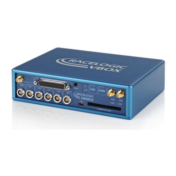
VBOX 3iSL User Guide Connection Data Front View of VBOX3iSL 3 pin LEMO socket 5 pin LEMO socket 2 pin LEMO socket Page 43 of 49 01/12/2011... - Page 44 VBOX 3iSL User Guide Connector 1 POWER Type Lemo 2 pin In/Out Description Range Power + 7V to 30V Ground Connector 2 AD 1 Type Lemo 3 pin In/Out Description Range Analogue 1 Output 0V to 5V Digital 2 Output...
- Page 45 VBOX 3iSL User Guide Connector 5 CAN Type Lemo 5 pin In/Out Description Range 12v RS232 Tx (PORT B) 12v RS232 Rx (PORT B) CAN Bus High (PORT A) CAN Bus Low (PORT A) +V Power Same as Power +...
-
Page 46: Analogue Input Connector
Channel 2 - Iso. GND Isolated Ground Channel 3 + Channel 3 - Channel 4 + Channel 4 - Note: A screw terminal connector block is available to purchase on request from your VBOX supplier. Page 46 of 49 01/12/2011... -
Page 47: Can Output
VBOX 3iSL User Guide CAN Output The VBOX 3iSL has a CAN output which is present on the 5-way connector output; Data format: Motorola; Baud rate: 500Kb/s. Format Motorola ID** Update Data Bytes rate * (3) Position – Latitude MMMM.MMMMM... - Page 48 (8) Vertical Velocity, 0.01 m/s per bit, signed. (9) Status. 8 bit unsigned char. Bit 0=VBOX Lite, Bit 1=Open or Closed CAN Bus (1=open), 2=VBOX3 (10) Status is an 8 bit unsigned char. Bit 0 is always set, Bit 3=brake test started, Bit 4 = Brake trigger active, Bit 5 = DGPS active (11) Distance, 0.000078125 meters per bit, unsigned.
-
Page 49: Contact Details
VBOX 3iSL User Guide Contact Details Racelogic Unit 10 Swan Business Centre Osier Way Buckingham Bucks MK18 1TB United Kingdom Email: support@racelogic.co.uk Web: www.racelogic.co.uk Document Updates Changes Date Init Page Change Draft 28-Jan-09 Draft Version of Document. 29-April-09 31 - 34...
Need help?
Do you have a question about the VBOX 3iSL and is the answer not in the manual?
Questions and answers