
Subscribe to Our Youtube Channel
Related Manuals for Eltek Valere Theia He-t


Summary of Contents for Eltek Valere Theia He-t
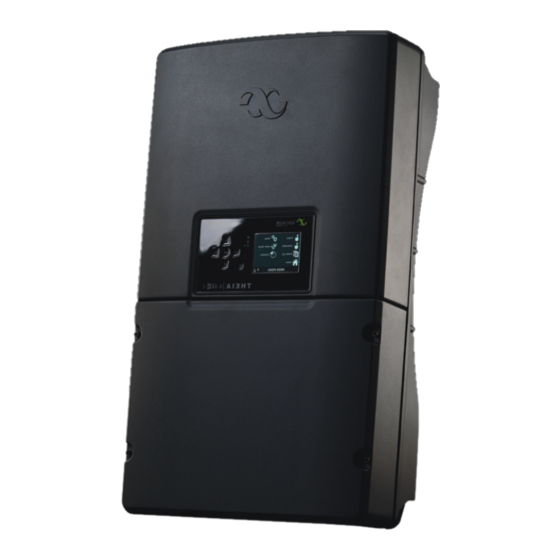
- Page 1 THEIA HE-t ™ String Inverter ~ 2.0 - 4.4 kW , 600 V USER MANUAL www.eltekvalere.com/renewable...
- Page 2 Information in this document is subject to change without notice and does not represent a commitment on the part of Eltek Valere. No part of this document may be reproduced or transmitted in any form or by any means —...
-
Page 3: Table Of Contents
8.4. Return and Disposal ......................73 9. Warranty ............................. 74 9.1. Warranty Service ......................74 9.2. Warranty Disclaimer ....................... 74 10. Technical Data .......................... 75 11. Contact Information ......................... 77 User Manual THEIA HE-t String Inverters 357115.013 Issue 1.0, 2011 April... -
Page 4: Introduction
1. Introduction The THEIA HE-t inverters are among the most efficient single phase grid connected (grid-tie) inverters on the market, which will result in high yields from the solar array. In a grid connected photovoltaic system, the interface between the solar array... -
Page 5: Product Overview
ÖNORM E 8001-4-712 IEC 61727 2.2. General Information Several variants of the THEIA HE-t are available for different configurations and country specific requirements. 2.2.1. Variants The instructions given in this User Manual are applicable to the following models of THEIA HE-t solar inverters: •... -
Page 6: Symbols Used
This symbol indicates that there is a potential for electric shock or electrocution. This symbol indicates an important safety note. Pay particular attention when the symbols appear in this User Manual! User Manual THEIA HE-t String Inverters 357115.013, Issue 1.0, 2011 March... - Page 7 Danger: High voltages are present S – NO: Serial Number for inverter identification DC: Direct current terminal Grounding: Ground terminal AC: Alternating current terminal User Manual THEIA HE-t String Inverters 357115.013 Issue 1.0, 2011 April...
-
Page 8: Unpacking And Inspection
2.4.1. Shipping Damage The THEIA HE-t inverters are thoroughly checked and tested in accordance with international standards and approvals prior to dispatch. They are carefully packed before shipping. However, if any damage to the inverter is found when delivered, please provide feedback to your local Eltek Valere representative immediately! 2.4.2. -
Page 9: Scope Of Delivery
2.4.5. Inverter Structure The housing of the THEIA HE-t inverter is designed to: • IP 65/NEMA 4X for indoor or outdoor use • Provide a degree of protection from dirt, rain, sleet, snow, dust, water, and corrosion •... - Page 10 The upper cover may only be removed by Eltek Valere authorized personnel. Removal of the upper cover by unauthorized persons voids the warranty! The lower cover protects the customer connection area, and may be removed by the system installer for electrical connection and maintenance of the inverter.
-
Page 11: Safety Precautions
3. Safety Precautions This chapter contains instructions on how to install, operate and maintain the THEIA HE-t inverters safely. These safety precautions must be read thoroughly and understood prior to the installation, so as to be able to handle the inverter correctly and maintain the warranty of the product. - Page 12 The inverter must only be operated in accordance with the information in this User Manual. DANGER: Operate the inverter as specified in this User Manual! The THEIA HE-t is a grid interactive inverter and must be used exclusively for its designed purpose, which is to convert PV-generated DC electricity into AC electricity to feed into the grid.
-
Page 13: Site Preparations
3.2. Site Preparations Observe the following precautions when mounting and installing the THEIA HE-t inverter on a suitable site. This is crucial to maintaining the efficiency of the inverter! 3.2.1. Mounting Sufficient ventilation and appropriate ambient temperatures are needed to prevent temperature build-up inside the inverter, which could lead to possible power losses. -
Page 14: Safety Equipment Required For Grid Connected Systems
Safety Equipment: The system installer is responsible for providing safety equipment that meets the requirements for both the DC and AC operations, and to protect the equipment and prevent personal injury, as per the local and national electrical regulations. User Manual THEIA HE-t String Inverters 357115.013, Issue 1.0, 2011 March... -
Page 15: Overcurrent Protection Devices
9.5A 12 A 20 A THEIA 2.9 HE-t 13.5A 17 A 30 A 18.0A 23 A 35 A THEIA 3.8 HE-t 21.0A 27 A 40 A THEIA 4.4 HE-t User Manual THEIA HE-t String Inverters 357115.013 Issue 1.0, 2011 April... - Page 16 Always use qualified assesment when selecting the appropriate kA ratings for the overvoltage protection device! • IEEE provides a good base for selecting kA ratings of the surge arrester: The THEIA HE-t inverters are designed for category B: 100 kA – 150 kA per phase. User Manual THEIA HE-t String Inverters...
-
Page 17: Installation
(See 10.Technical Data). DANGER: Ensure a safe installation of the inverter! Follow the installation instructions carefully to prevent poor performance or possible lethal consequences. User Manual THEIA HE-t String Inverters 357115.013 Issue 1.0, 2011 April... - Page 18 • Drill the holes and fasten the bracket with the number of screws required to support the hanging weight of the inverter. • Recommended height for the customer onnection area: 1000 - 1400 mm / 39.4 - 55.1 inches above floor level. User Manual THEIA HE-t String Inverters 357115.013, Issue 1.0, 2011 March...
- Page 19 • Lift the inverter and guide the upper hooks into the slots on the bracket. • Align the lower hooks into the slots. • Slide the inverter onto the bracket. Figure 4.2.4: Inverter onto bracket User Manual THEIA HE-t String Inverters 357115.013 Issue 1.0, 2011 April...
- Page 20 • The padlock is not a part of the scope of supply. Figure 4.2.6: Theft protection NOTICE! Check that the inverter is properly fastened and secured to the bracket prior to the electrical wiring. User Manual THEIA HE-t String Inverters 357115.013, Issue 1.0, 2011 March...
-
Page 21: Electrical Installation
The conductor cross section area and the disconnector ratings must conform to the ratings required by local and national electrical regulations. • Use adequately sized conductors with the correct temperature rating and sunlight resistance. User Manual THEIA HE-t String Inverters 357115.013 Issue 1.0, 2011 April... -
Page 22: Connection Area
4. DC ground terminal 5. Stringbox with fuse holders and DC switch 6. AC terminal block Figure 4.3.1: Customer connection area with stringbox with DC fuse holders and DC switch User Manual THEIA HE-t String Inverters 357115.013, Issue 1.0, 2011 March... - Page 23 1. CAN terminal 2. Ethernet connection 3. Internal DC terminal blocks 4. DC ground terminal 5. Connector panel 6. AC terminal block Figure 4.3.3: Customer connection area with connector panel User Manual THEIA HE-t String Inverters 357115.013 Issue 1.0, 2011 April...
- Page 24 • Follow the safety instructions and specifications from the different PV module manufacturers regarding grounding requirements. • All metal parts of the THEIA HE-t inverters are electrically bonded to ground through the terminal labeled GND on the AC side • Only valid for France: According to UTE C 15-712-1 a minimum cross section area of 6.0 mm²...
- Page 25 The voltage generated by PV modules is inversely proportional to the temperature; at lower temperatures the PV voltage increases from the nameplate rating and at higher temperatures the PV voltage decreases from the nameplate rating. Refer to 3.1.2. Operation. User Manual THEIA HE-t String Inverters 357115.013 Issue 1.0, 2011 April...
- Page 26 The Stringbox can be equipped with DC fuse holders, DC switch and plug-in connectors or cable glands. P1, P2, P3: Positive connectors N1, N2, N3: Negative connectors Figure 4.3.6: Optional DC connectors User Manual THEIA HE-t String Inverters 357115.013, Issue 1.0, 2011 March...
- Page 27 • Connect the grounding strap between *N4 and the DC ground terminal in the customer connection area (See 4.3.3. Grounding). Wiring Diagram Positive grounded PV String Negative grounded PV String User Manual THEIA HE-t String Inverters 357115.013 Issue 1.0, 2011 April...
- Page 28 (See 4.3.3. Grounding). Negative grounded PV String • Connect the grounding strap between *N4 and the DC ground terminal in the customer connection area (See 4.3.3. Grounding). User Manual THEIA HE-t String Inverters 357115.013, Issue 1.0, 2011 March...
- Page 29 Terminals labeled Grounded **N4: Grounding terminal **P4: Ungrounded terminal **N5: Terminal for the grounding strap DS: DC Switch Figure 4.3.11: Stringbox with DC switch and no DC fuse holders User Manual THEIA HE-t String Inverters 357115.013 Issue 1.0, 2011 April...
- Page 30 A DC switch must then be installed separately by the system installer in compliance with the relevant local and national electrical regulations. N1, N2, N3: Negative connectors P1, P2, P3: Positive connectors Figure 4.3.12: Connector panel with optional DC connectors User Manual THEIA HE-t String Inverters 357115.013, Issue 1.0, 2011 March...
- Page 31 • With three strings, two of the string conductors must be connected to the same terminal, so that the grounding strap has a terminal for itself. Wiring Diagram Positive grounded PV String Negative grounded PV String User Manual THEIA HE-t String Inverters 357115.013 Issue 1.0, 2011 April...
- Page 32 DANGER: Be aware of high currents! If the DC terminals are mixed up during connection, high currents are generated in the conductors, which can pose shock hazards. User Manual THEIA HE-t String Inverters 357115.013, Issue 1.0, 2011 March...
- Page 33 There is no connection between the pins. Positive grounded PV String The jumper short-circuits pin 1 and pin 2. Negative grounded PV String The jumper short-circuits pin 2 and pin 3. User Manual THEIA HE-t String Inverters 357115.013 Issue 1.0, 2011 April...
- Page 34 Turn OFF the AC circuit breaker(s) before connecting the inverter to the AC grid to avoid shock hazards. The THEIA HE-t series are single phase output inverters, which are designed so that they can be connected to a three-phase system. When several inverters are connected together, they must be distributed evenly between the grid phases.
- Page 35 CAN allows communication between several inverters. 1. Slave inverter 2. Master inverter 3. CAN 4. Ethernet 5. Computer Figure 4.3.16: Network connections User Manual THEIA HE-t String Inverters 357115.013 Issue 1.0, 2011 April...
- Page 36 H connected to H, L to L etc. Recommended tightening torque is 0.2 Nm / 0.15 ft-lbf. 5. Tighten the cable gland firmly. NOTICE! User Manual THEIA HE-t String Inverters 357115.013, Issue 1.0, 2011 March...
-
Page 37: Checks Before Start Up
Recommended tightening torque is 1.0 Nm / 0.74 ft- lbf. CAUTION: Ensure to tighten the inverter lower cover! Verify that the lower cover is correctly secured so no moisture enters the housing and damages the electronic components. User Manual THEIA HE-t String Inverters 357115.013 Issue 1.0, 2011 April... -
Page 38: Start Up
5. Start Up This chapter provides instructions to ensure a safe start-up of the THEIA HE-t inverter. 5.1. How to Start Up A minimum available voltage of 230 V and a DC power of >7 W is required before the inverter starts feeding power to the grid. - Page 39 Cancel: Stop operation / back to value left previous menu item • The selected item is always highlighted in yellow. • A registered touch of a button causes a “click” sound to be heard. User Manual THEIA HE-t String Inverters 357115.013 Issue 1.0, 2011 April...
- Page 40 1b. Language Selection Default – English Up or Down - Navigate through the list to Enter – Call up the list of languages find the preferred language Enter - Confirm User Manual THEIA HE-t String Inverters 357115.013, Issue 1.0, 2011 March...
- Page 41 4. Set as Master Unit Default – No Enter – Call up the options Up or Down – Navigate through the options YES or NO Enter - Confirm User Manual THEIA HE-t String Inverters 357115.013 Issue 1.0, 2011 April...
- Page 42 5 hours of feeding power into the grid after installation. Thereafter it is only accessible using the Installer password, which may only be obtained for installers and grid operators by contacting Eltek Valere. CAUTION: Ensure correct country settings! The selected country must match the actual installation site;...
- Page 43 • It is possible to navigate between the characters by using the Up arrow to set the marker into the text window, then using Left and Right to navigate between the characters. • There is a maximum space for 19 symbols in the text window. User Manual THEIA HE-t String Inverters 357115.013 Issue 1.0, 2011 April...
- Page 44 10. Message 2 Enter – Call up the keyboard This message field is to help distinguish and identify specific inverters in a larger PV plant, or for any other information. User Manual THEIA HE-t String Inverters 357115.013, Issue 1.0, 2011 March...
- Page 45 • If the Start Up phase is correctly carried out the inverters are ready to use. They are fully automatic during normal operation, and no manual control is necessary for feeding power into the grid. User Manual THEIA HE-t String Inverters 357115.013 Issue 1.0, 2011 April...
-
Page 46: Self Test For Italy
The test needs some seconds to start. The test can fail if the irradiation is insufficient, as the inverter is unable to feed power to the grid. Restart the test later. User Manual THEIA HE-t String Inverters 357115.013, Issue 1.0, 2011 March... - Page 47 AC off Minimum allowed disconnection time Time from equalization to disconnection PASS The second sequence is successfully carried out FAIL The second sequence has failed – try again later User Manual THEIA HE-t String Inverters 357115.013 Issue 1.0, 2011 April...
- Page 48 Inverter Command menu. The test results are stored in Commands > Inverter Commands > Results Self Test If the test fails 4 times, contact Eltek Valere. User Manual THEIA HE-t String Inverters 357115.013, Issue 1.0, 2011 March...
-
Page 49: Operation
The information and values in the menus Home, Status, Event log and Statistics are read-only, while the information and values in the menus Setup, Commands and Alarm Setup can be modified. Figure 6.2.1: Main menu User Manual THEIA HE-t String Inverters 357115.013 Issue 1.0, 2011 April... - Page 50 Default Owner password is 0003, but can be changed in Setup>General Setup>Password. If the password is lost or forgotten, contact Eltek Valere. Installer Read and set all values. The Installer password is based on the serial number; and can only be obtained by contacting Eltek Valere.
- Page 51 Shutdown; inverter/system failure or unstable operational conditions Service Mode; inverter can be manually overridden Yellow Lower Section The lower section contains a shortcut to the Main Menu and the current date and time. User Manual THEIA HE-t String Inverters 357115.013 Issue 1.0, 2011 April...
-
Page 52: Inverter Status
Total energy harvest throughout the day Temperature Temperature inside the inverter Level for a safe insulation to prevent injury or equipment failure Isolation Resistance Operating Hours Total inverter running time from first start-up User Manual THEIA HE-t String Inverters 357115.013, Issue 1.0, 2011 March... - Page 53 Gateway Network point acting as entrance to another network With several inverters connected together, one inverter must be the Master Setting master and the rest of the inverters slaves User Manual THEIA HE-t String Inverters 357115.013 Issue 1.0, 2011 April...
- Page 54 Unique identifier for each inverter. Also to be found on the product label THEIA Part Number Identifier for each inverter hardware configuration within Eltek Valere Unique version name for keeping track of the development of different THEIA Version inverter versions within Eltek Valere GUI Software Part No The GUI (Graphical User Interface) software part number.
- Page 55 • After 5 hours of feeding in power to the grid after installation the Installer password must be used to change the country settings. The Installer password is avaialable for installers and grid operators only by contacting Eltek Valere. • The question “Change country settings?” appears in the display.
- Page 56 Deletes the energy log items and summarized values Data Log Deletes the 15 minutes average power values Self-Test Start Self-Test (Italy only) Result Self-Test View the results from the last run Self-Test (Italy only) User Manual THEIA HE-t String Inverters 357115.013, Issue 1.0, 2011 March...
-
Page 57: Alarm Setup
Send operation mode change to email 2 (sent immediately) Send mode on email 2 Send alarm on email 2 Send warning and alarm change to email 2 (sent immediately) User Manual THEIA HE-t String Inverters 357115.013 Issue 1.0, 2011 April... -
Page 58: Event Log
Depending on the feed-in tariff: Cash value of the feed-in energy in currency/kWh emissions avoided by using solar power compared to fossil fuel in avoided kg/kWh Peak Power Largest instantaneous amount of power produced [W] User Manual THEIA HE-t String Inverters 357115.013, Issue 1.0, 2011 March... -
Page 59: Connection Between Inverter And Computer
5. Select Use the following IP address. Enter the default parameters: IP address 192.168.10.10, subnet mask 255.255.255.0. Click OK and OK To connect to the THEIA HE-t, the inverter’s IP address must be entered into the web browser address line. NOTICE! With several inverters connected together via CAN bus the CAT5 cable must be attached to the master inverter only. - Page 60 ‘advanced settings’ of the router/switch, but will vary from manufacturer to manufacturer. Port ‘80’ of the router must be forwarded to the static IP User Manual THEIA HE-t String Inverters 357115.013, Issue 1.0, 2011 March...
-
Page 61: Internal Web Server
• Default administrator account is: User: admin, Password: admin • This should be changed if the web server is connected to the internet. The web page is best viewed in Firefox 4.0 or Internet Explorer 8.0. User Manual THEIA HE-t String Inverters 357115.013 Issue 1.0, 2011 April... -
Page 62: Troubleshooting
Inverter failure (W/A) Inverter failure Output circuit breaker open AC circuit breaker(s) is - Turn ON the AC circuit open breaker(s)* - If already ON, contact the system installer User Manual THEIA HE-t String Inverters 357115.013, Issue 1.0, 2011 March... - Page 63 (See 10. Technical Data) - Check if the ventilation is sufficient, the minimum distances are compliant with those stated in User Manual THEIA HE-t String Inverters 357115.013 Issue 1.0, 2011 April...
- Page 64 - Check that the country settings have been successfully set in Setup > Grid Setup - If the failure persists, contact the system installer User Manual THEIA HE-t String Inverters 357115.013, Issue 1.0, 2011 March...
- Page 65 Grid fault, still running (W) Fault ride-through VDR fault DC side The varistors on the DC - Contact your distributor for new side are damaged. parts * Reserved for future use User Manual THEIA HE-t String Inverters 357115.013 Issue 1.0, 2011 April...
-
Page 66: Maintenance
This chapter explains how to switch OFF and discharge the inverter safely. It also provides an overview of important regular maintenance procedures to ensure trouble-free operation of the THEIA HE-t inverters. Finally, it is explained how to remove and return the inverters. 8.1. Switch-Off... - Page 67 CAUTION: The inverter upper cover must be opened by authorized service personnel only! The discharge process using a resistor must be performed by Eltek Valere authorized service personnel only, as it requires removal of the inverter upper cover, which can damage internal components and invalidate the warranty! •...
-
Page 68: Regular System Inspections
8.2. Regular System Inspections The THEIA HE-t inverters are manufactured to operate trouble-free for several years. Performing regular maintenance will ensure high efficiency and a long service life. CAUTION: Only qualified persons to perform work inside the inverter! Maintenance work involving removal of the inverter covers must be performed by qualified persons only, due to damage to electrical components and the warranty of the product. - Page 69 AC is off. 8.2.7. Inverter It is recommended that the inside of the inverter is checked by the system installer for humidity and dust every 3 – 4 years. User Manual THEIA HE-t String Inverters 357115.013 Issue 1.0, 2011 April...
- Page 70 • If the fan fails, the inverter continues to feed the same amount of power until a certain temperature threshold, at which point it starts to reduce power to protect itself against overheating. • A new fan can be ordered from Eltek Valere with part number 276747. Removal of the fan Insertion of the fan Figure 8.2.2: Removal of the fan...
- Page 71 • A message is shown in the display when a DC varistor needs replacement (See 7.2. Table of Events). • Replace the damaged varistor with DC Varistor Kit ordered from your local Eltek Valere representative, part number 271539. The two varistors on the...
- Page 72 • No alarms are raised regarding the condition of the varistors on the AC side. Therefore, they need to be checked regularly (at least once per year) or after lightning strikes. • Replace the damaged varistor with DC Varistor Kit ordered from Eltek Valere, part number 263574.
-
Page 73: Replace Devices
• Return to the given address in the respective country/continent 8.4.2. Disposal In case of end of service life, the inverter can be returned to your distributor, to Eltek Valere direct, or disposed of in the respective country. The shipping to the distributor or Eltek Valere is paid by the sender. -
Page 74: Warranty
9. Warranty This chapter gives a brief introduction to the valid warranty of the THEIA HE-t inverters. The inverters are compatible with all relevant standards and are guaranteed to be free of defects from the date of purchase. 9.1. Warranty Service The standard warranty applies for 5 years after the date of installation, with an optional extension of up to 20 years. -
Page 75: Technical Data
Communication Graphical, color display with touch sense buttons, 3x LEDs for visual status indication, embedded web-server, Ethernet, CAN bus Warranty 5 years, 10 years, 15 years, 20 years options User Manual THEIA HE-t String Inverters 357115.013 Issue 1.0, 2011 April... - Page 76 User Manual THEIA HE-t String Inverters 357115.013, Issue 1.0, 2011 March...
-
Page 77: Contact Information
Phone: +1 (469) 330 9100 Fax: +39 06 41 405 890 Fax: +1 (469) 330 9101 Email: info@eltekvalere.it Email: sales.us@eltekvalere.com Web: www.eltekvalere.it Web: www.eltekvalere.com/us Find your local office at: http://www.eltekvalere.com User Manual THEIA HE-t String Inverters 357115.013 Issue 1.0, 2011 April... - Page 78 www.eltekvalere.com/renewable...
Need help?
Do you have a question about the Theia He-t and is the answer not in the manual?
Questions and answers