Table of Contents
Advertisement
Quick Links
Advertisement
Table of Contents

Related Manuals for Eltek Valere PWS Series


Summary of Contents for Eltek Valere PWS Series
- Page 1 DC/AC INVERTER PWS Series USER MANUAL UM_PWS_E_R1.2...
- Page 2 Supplier: ELTEK VALERE INDUSTRIAL GmbH Schillerstraße 16 D-32052 Herford + 49 (0) 5221 1708-210 + 49 (0) 5221 1708-222 Email Info.industrial@eltekvalere.com Internet http://www.eltekvalere-industrial.com © Copyright ELTEK VALERE INDUSTRIAL 2008. All rights reserved. ELTEK VALERE INDUSTRIAL ©2008 UM_PWS_E_R1.2...
- Page 3 The current revision status of this user manual is the following: Revision: Date: 2009-03-18 Revision Description of change Writer Date Former version “PWS_E1_neutral_20070416.doc” 2008-09-17 comprehensively reworked Minor text modifications and the new revision status 2008-10-29 numbering (X.X) inserted. Up-to-date photos inserted 2009-03-18 ELTEK VALERE INDUSTRIAL ©2008 UM_PWS_E_R1.2...
-
Page 4: Table Of Contents
Figure 7) - Mounting set for PWS-F..........................13 Figure 8) - Potentiometer and testjack........................16 Figure 9) - Detail: Rear side switch S2 ........................17 Figure 10) - PWS-F dimensions ............................. 21 Figure 11) - PWS-W dimensions............................ 21 ELTEK VALERE INDUSTRIAL ©2008 UM_PWS_E_R1.2... -
Page 5: Safety Instructions And Waste Disposal Rules
The above statement from EU directive 2002/96/EC applies to all electric devices installed within EU countries. In countries outside the EU, different rules may apply regarding waste disposal of electric devices. For more information about waste disposal of your discarded equipment, contact your ELTEK VALERE INDUSTRIAL partner. ELTEK VALERE INDUSTRIAL ©2008 UM_PWS_E_R1.2... -
Page 6: General Information
Optionally, versions with an included static bypass switch, special output voltages, special output frequency or further special models are available on request. 2.1 Typical applications Figure 1) - PWS-F in parallel operation Figure 2) - PWS-F in parallel operation with static bypass switch ELTEK VALERE INDUSTRIAL ©2008 UM_PWS_E_R1.2... -
Page 7: Type List
402-POC-012.00 PWS-1.0F 402-POC-033.00 PWS-2.5F Parallel operation choke 402-POC-050.00 PWS-5.0F Mounting set 880-MEC-MKT.03 PWS-F versions Internal static transfer switch Several types, depending on the PWS-F and PWS wall cabinet used PWS versions Extended AC distribution board ELTEK VALERE INDUSTRIAL ©2008 UM_PWS_E_R1.2... -
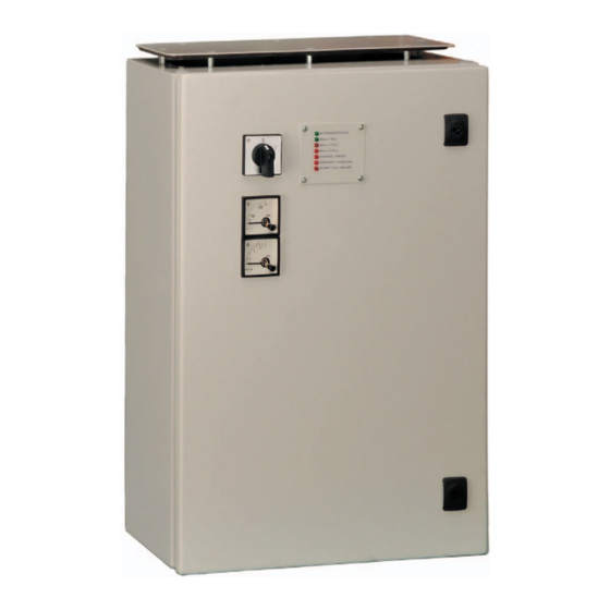
Page 8: Front View, Operating And Indicator Elements
The voltmeter indicates the AC output voltage, the ammeter indicates the AC output current. With the switch S1 the inverter can be switched ON /OFF. NOTE: For more information about the indicator and operating elements read the following sections. ELTEK VALERE INDUSTRIAL ©2008 UM_PWS_E_R1.2... -
Page 9: Electrical Connectors
SYNC-SIG (pins 7) with each other. If the inverters operate in combination with a static bypass switch UNB, it is also necessary, to inter- connect all SYNC-STAT (pins 8) with each other, including SYNC-STAT of the UNB. ELTEK VALERE INDUSTRIAL ©2008 UM_PWS_E_R1.2... - Page 10 SYNC-SIG (pins 7) with each other. If the inverters operate in combination with a static bypass switch UNB, it is also necessary, to inter- connect all SYNC-STAT (pins 8) with each other, including SYNC-STAT of the UNB. ELTEK VALERE INDUSTRIAL ©2008 UM_PWS_E_R1.2...
-
Page 11: Electrical Connectors Pws-W
DC input AC output Signals coll. failure: COM coll. failure: NO coll. failure: NC SYNC-GND SYNC-SIG SYNC-STAT No collective failure is existent: COM and NO are closed. Collective failure is existent: COM and NC are closed. ELTEK VALERE INDUSTRIAL ©2008 UM_PWS_E_R1.2... -
Page 12: Cooling And Air Flow Direction
For PWS-W a minimum space of 2U (approx. 90mm) above the top of the module (see figure 6b), item “A”) is recommended. Figure 6a) - Module air flow, PWS-F Figure 6b) - Module air flow, PWS-W ELTEK VALERE INDUSTRIAL ©2008 UM_PWS_E_R1.2... -
Page 13: Handling
For the safety of individuals, the connection of a non-fused protective earth conductor generally is required. Due to the specific overload and short circuit behaviour of the PWS, additional safety meas- ures are to be arranged at the output (e. g. ground fault circuit interrupter). ELTEK VALERE INDUSTRIAL ©2008 UM_PWS_E_R1.2... -
Page 14: Single Inverter
For this application, it is recommended to check individually the short circuit behavior of the system. Due to the voltage losses at the inductance of the parallel operation choke, the voltage deviation value exceeds the specified data of the data sheet of the PWS. ELTEK VALERE INDUSTRIAL ©2008 UM_PWS_E_R1.2... -
Page 15: Led Indications
Collective failure: The delay time is 20s; the relay contact reacts at the COLL. FAILURE same time. The following failures are combined: Vin<, Vin>, ERROR, OVERLOAD/TEMP. Maximum contact load: Vmax. 110V /Imax. <0.45A Vmax. 60V /Imax. <1A Vmax. 24V /Imax. <8A ELTEK VALERE INDUSTRIAL ©2008 UM_PWS_E_R1.2... -
Page 16: Monitoring
(1V =100V). But it is recommended to measure the output voltage Testjack at the output of the module with consideration of possible voltage losses at the internal wiring and parallel operation choke. Figure 8) - Potentiometer and testjack ELTEK VALERE INDUSTRIAL ©2008 UM_PWS_E_R1.2... -
Page 17: Rear-Side Switch S2 (Remote Switch-On Function)
For a faultless remote switch on function it is important that the wiring between the inverters and static bypass switch (remote switch on wire) is correct. INFO: The PWS-F series is serially fitted with the rear side switch since August 2008 (date of manufacture). ELTEK VALERE INDUSTRIAL ©2008 UM_PWS_E_R1.2... -
Page 18: Maintenance
→ check/adjust output voltage Is the voltage adjustment (potentiometer) correct? If the unit still does not work even though all checks are done, please contact your sales agent or the Eltek Valere Industrial service department. ELTEK VALERE INDUSTRIAL ©2008 UM_PWS_E_R1.2... -
Page 19: Technical Specifications
12 modules with external parallel operation choke, Parallel operation load sharing approx. 5%, External synchronization Analogue measurement Vout, Iout instruments Environmental: Ambient temperature Operation: -20°C to +55°C, storage: -40°C to +85°C Climatic conditions according to IEC 721-3-3 class 3K3/3Z1/3B1/3C2/3S2/3M2 ELTEK VALERE INDUSTRIAL ©2008 UM_PWS_E_R1.2... -
Page 20: Specific Data
50/25 52/64 20.0 21.7 25/25 52/64 The PWS-W is serially fitted with internal input and output fuses. The PWS-F has no internal fuses. It is recommended to use external fuses according to the table above. ELTEK VALERE INDUSTRIAL ©2008 UM_PWS_E_R1.2... -
Page 21: Dimensional Drawings Pws-F
6.4 Dimensional drawings PWS-W Figure 11) - PWS-W dimensions PWS-W A (mm) B (mm) C (mm) D (mm) E (mm) The dimensions of the slotted holes of the wall holder mountings are 8.5 x 12.5mm. ELTEK VALERE INDUSTRIAL ©2008 UM_PWS_E_R1.2... -
Page 22: Notes
DC/AC Inverter PWS series User Manual Page 22 (24) 7. Notes ELTEK VALERE INDUSTRIAL ©2008 UM_PWS_E_R1.2... - Page 23 DC/AC Inverter PWS series User Manual Page 23 (24) Notes ELTEK VALERE INDUSTRIAL ©2008 UM_PWS_E_R1.2...
- Page 24 Supplier: ELTEK VALERE INDUSTRIAL GmbH Schillerstraße 16 D-32052 Herford + 49 (0) 5221 1708-210 + 49 (0) 5221 1708-222 Email Info.industrial@eltekvalere.com Internet http://www.eltekvalere-industrial.com © Copyright ELTEK VALERE INDUSTRIAL 2008. All rights reserved.
Need help?
Do you have a question about the PWS Series and is the answer not in the manual?
Questions and answers