Table of Contents
Advertisement
Advertisement
Table of Contents

Subscribe to Our Youtube Channel
Related Manuals for Eltek Valere UNV-F 2.5


Summary of Contents for Eltek Valere UNV-F 2.5
- Page 1 DC/AC INVERTER UNV-F 2.5/3.3/5.0 USER MANUAL UM_UNVF_E_R2.0...
- Page 2 ELTEK VALERE DEUTSCHLAND GmbH GB Industrial Schillerstraße 16 D-32052 Herford + 49 (0) 5221 1708-210 + 49 (0) 5221 1708-222 Email Info.industrial@eltekvalere.com Internet http://www.eltekvalere.com 2009. ELTEK VALERE DEUTSCHLAND GmbH. All rights reserved. ©2009. ELTEK VALERE DEUTSCHLAND GmbH. UM_UNVF_ E_R2.0...
- Page 3 2009-07-31 Revision Description of change Writer Date 01-03 Minor text modifications ELTEK VALERE INDUSTRIAL layout inserted 2008-01-29 New revision status numbering (X.X) introduced, section “Error 2009-04-20 indication on the displays” inserted. Minor reworking at sections 3.4, 4.2, 7. 2009-07-31 ©2009. ELTEK VALERE DEUTSCHLAND GmbH.
-
Page 4: Table Of Contents
LEMENTS 3.3 E ............................9 LECTRICAL ONNECTORS 3.3.1 Electrical Connector X1 for UNV-F 2.5 – 3.3kVA, UNV60-5.0F and UNV110-5.0F ....9 3.3.2 Electrical Connector X1 for UNV48-5.0F (HAN K 6/6)..............10 3.3.3 CAN-Bus connectors CAN1 & CAN2....................11 3.4 C ..........................11... -
Page 5: Safety Instructions
In the case of waste disposal of your discarded equipment we recommend to contact a waste management company. ©2009. ELTEK VALERE DEUTSCHLAND GmbH. UM_UNVF_ E_R2.0... -
Page 6: General Information
The priority source is programmable at the UNB unit (see separate manual). 2.1 Typical Applications (a) Inverter in parallel operation without UNB b) Inverter in parallel operation with UNB ©2009. ELTEK VALERE DEUTSCHLAND GmbH. UM_UNVF_ E_R2.0... -
Page 7: Type Range/Equipment
Mounting set for 19’’ cabinet (not for UNV48-5.0F): Mat. code 880-MEC-MKT.01 Mounting set for 19’’ cabinet (for UNV48-5.0F): Mat. code 880-MEC-MKT.02 The mounting set is necessary to fit the UNV module in a 19’’ compatible cabinet (see section 4.2 “commissioning”). ©2009. ELTEK VALERE DEUTSCHLAND GmbH. UM_UNVF_ E_R2.0... -
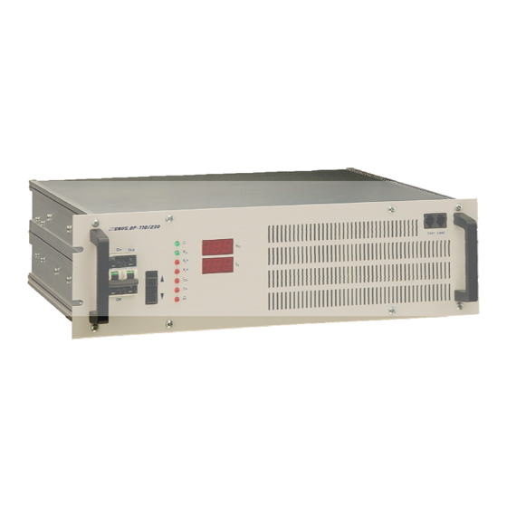
Page 8: Front View/Operation Elements
Io> (Overload) T> (Overtemperature) Bell symbol (General alarm) Two digital displays indicate the output voltage and output current values. Detailed information concerning signalling and monitoring are described in the following sections. ©2009. ELTEK VALERE DEUTSCHLAND GmbH. UM_UNVF_ E_R2.0... -
Page 9: Electrical Connectors
UNV-F User Manual Page 9 (28) 3.3 Electrical Connectors 3.3.1 Electrical Connector X1 for UNV-F 2.5 – 3.3kVA, UNV60-5.0F and UNV110-5.0F X1 (HAN-K4/8) socket outlet (DC input voltage / AC output voltage and signalling): X1/Pin Designation DC input, plus pole... -
Page 10: Electrical Connector X1 For Unv48-5.0F (Han K 6/6)
**In parallel operation the contacts SYNC – GND and SYNC – SIG of each inverter have to be wired. *** In operation with an UNB it is necessary to interconnect the synchronization bus (contacts SYNC – GND, SYNC – SIG and SYNC – STAT) between the inverter(s) and the UNB. ©2009. ELTEK VALERE DEUTSCHLAND GmbH. UM_UNVF_ E_R2.0... -
Page 11: Can-Bus Connectors Can1 & Can2
Please note: The ambient temperature should not exceed a maximum of 45°C. If the UNV-F module is integrated into a cabinet, the ambient temperature should not exceed a maximum of 40°C. ©2009. ELTEK VALERE DEUTSCHLAND GmbH. UM_UNVF_ E_R2.0... -
Page 12: Communication Interface
Please avoid too much pressure. If the unit does not fit in please start again with the complete slide-in process. Mount the unit with 4 screws (M4x12). Mounting set for UNV-F (shown with an UNV-F unit). ©2009. ELTEK VALERE DEUTSCHLAND GmbH. UM_UNVF_ E_R2.0... -
Page 13: Single Inverter
CAN-Bus. The specific address per inverter (module) must be allocated with the adjustment keys in the “basic menu PM1” (please see the section 4.5. and the following). The standard address (factory set) of the inverter is “001”. ©2009. ELTEK VALERE DEUTSCHLAND GmbH. UM_UNVF_ E_R2.0... -
Page 14: Led Indications
Collective failure; the delay time of the relay alarm is adjustable**; relay contact at X1; all single failures are included. * Adjustment of the threshold values, please see section 4.5 **Only with the service menu PM2. ©2009. ELTEK VALERE DEUTSCHLAND GmbH. UM_UNVF_ E_R2.0... -
Page 15: Internal Monitoring
This is indicated by a blinking LED T>. * Adjustment of the threshold values please see section 4.5 //**Only with the service menu PM2. ©2009. ELTEK VALERE DEUTSCHLAND GmbH. UM_UNVF_ E_R2.0... -
Page 16: Adjustment Of The Standard And Threshold Values
(the upper display shows a horizontal line / the changed value is saved at this moment) press both keys UP/DOWN () for approximately three seconds to change back to the operation mode (For the table of the adjustable parameters in the basic menu PM1, please see section 4.5.3) ©2009. ELTEK VALERE DEUTSCHLAND GmbH. UM_UNVF_ E_R2.0... -
Page 17: Diagram "Standard Display During Operation/Display Of Input And Output Parameters
DC/AC Inverter UNV-F User Manual Page 17 (28) 4.5.1 Diagram “Standard display during operation/display of input and output parameters” The continuation of the diagram is on the next page! ©2009. ELTEK VALERE DEUTSCHLAND GmbH. UM_UNVF_ E_R2.0... - Page 18 DC/AC Inverter UNV-F User Manual Page 18 (28) Continuation of the previous page: “” By pressing both keys short-time at the position (Hardware reset) the device switches off and restarts ©2009. ELTEK VALERE DEUTSCHLAND GmbH. UM_UNVF_ E_R2.0...
-
Page 19: Diagram "Adjustment Mode
Page 19 (28) 4.5.2 Diagram “Adjustment mode” For switching to the adjustment mode shortly press both keys together at any position within the display of input and output parameters (except for the position “hardware reset”). ©2009. ELTEK VALERE DEUTSCHLAND GmbH. UM_UNVF_ E_R2.0... - Page 20 DC/AC Inverter UNV-F User Manual Page 20 (28) You can leave the adjustment mode by pressing both keys for approximately three seconds. ©2009. ELTEK VALERE DEUTSCHLAND GmbH. UM_UNVF_ E_R2.0...
-
Page 21: Table "Adjustable Parameters
230.25 corresponds to 230.5 corresponds to 230.75 With each click at the UP/Down keys the dot moves. After four times clicking (4/4), the voltage value is increased (or decreased) for 1V. ©2009. ELTEK VALERE DEUTSCHLAND GmbH. UM_UNVF_ E_R2.0... -
Page 22: Maintenance
Vo not value (see item 4.5.2) correct? If the unit still does not work even though all checks are done, please contact your sales agent or the service department of Eltek Valere Deutschland. ©2009. ELTEK VALERE DEUTSCHLAND GmbH. UM_UNVF_ E_R2.0... -
Page 23: Error Indication On The Displays
„8“ means “over temperature” (LED „T>“ is ON) or “input DC/DC converter is not ok”. „128“ means „output under voltage”. Because the module has switched OFF there is no output voltage. Due to this, the error „output under voltage“ also is included. ©2009. ELTEK VALERE DEUTSCHLAND GmbH. UM_UNVF_ E_R2.0... - Page 24 SHd = Shutdown Lower display: ovL = short circuit/overload An intended shutdown via CAN-Bus by static bypass switch UNB is indicated as follows: Upper display: OFF (shutdown) Lower display: CAn (via CAN-Bus) ©2009. ELTEK VALERE DEUTSCHLAND GmbH. UM_UNVF_ E_R2.0...
-
Page 25: Technical Specifications
CAN-Bus interface for communication with static transfer switch UNB Environmental Ambient temperature Operation: 0°C up to +45°C(max. 40°C fitted in cabinets), storage: -40°C up to +85°C Climatic conditions according to IEC 721-3-3 class 3K3/3Z1/3B1/3C2/3S2/3M2 Max. installation altitude ≤ 1500m ©2009. ELTEK VALERE DEUTSCHLAND GmbH. UM_UNVF_ E_R2.0... - Page 26 Front panel: powder coating RAL 7035; neutral, black print RAL 9005; constructive parts: anodized metal Compliances CE conformity Compliance to safety EN60950-1; VDE0100 T410; VDE0110; EN50178; EN60146 standards Compliance to EMC EN55011/22 class “B“; EN61000-4 T2-5 standards ©2009. ELTEK VALERE DEUTSCHLAND GmbH. UM_UNVF_ E_R2.0...
-
Page 27: Dimensional Drawings
DC/AC Inverter UNV-F User Manual Page 27 (28) 7.1 Dimensional drawings UNV-2.5F/UNV-3.3F: UNV-5.0F: ©2009. ELTEK VALERE DEUTSCHLAND GmbH. UM_UNVF_ E_R2.0... - Page 28 Supplier: ELTEK VALERE DEUTSCHLAND GmbH GB Industrial Schillerstraße 16 D-32052 Herford + 49 (0) 5221 1708-210 + 49 (0) 5221 1708-222 Email Info.industrial@eltekvalere.com Internet http://www.eltekvalere.com 2009. ELTEK VALERE DEUTSCHLAND GmbH. All rights reserved.
Need help?
Do you have a question about the UNV-F 2.5 and is the answer not in the manual?
Questions and answers
What is the default password for unv48-5.0