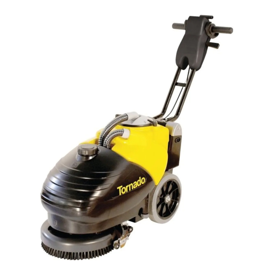
Tornado BD 14/4 Operation & Maintenance Manual
Compact autoscrubber
Hide thumbs
Also See for BD 14/4:
- Operation & maintenance manual (39 pages) ,
- Dealer training manual (20 pages)

Related Manuals for Tornado BD 14/4


Summary of Contents for Tornado BD 14/4
- Page 1 Operations & Maintenance Manual For Commercial Use Only COMPACT AUTOSCRUBBER BD 14/4 99414 Form No. L9740...
-
Page 2: Table Of Contents
©Tornado, LLC. All rights reserved LEGEND INSTRUMENT BOARD AND CONTROLS LEGEND MACHINE TECHNICAL DESCRIPTION INTRODUCTORY COMMENT GENERAL RULES OF SECURITY SYMBOLOGY BEFORE USE HANDLING OF THE PACKED MACHINE UNPACKING OF THE MACHINE MOVEMENTS OF THE HANDLE BAR BATTERIES BATTERIES RECHARGING (STANDARD VERSION WITH... -
Page 3: Legend Instrument Board And Controls
LEGEND INSTRUMENT BOARD AND CONTROLS 5. SQUEEGEE LIFT LEVER 1. MAIN SWITCH WITH SIGNAL LAMP 6. HANDLE BARS 2. BRUSH MOTOR SWITCH WITH SIGNAL 7. BRUSH ACTIVATION LEVERS LAMP 8. HANDLE BAR RELEASE LEVER 3. SUCTION MOTOR SWITCH WITH SIGNAL LAMP 4. -
Page 4: Legend Machine
LEGEND MACHINE 9. WHEELS 16. RECOVERY TANK 10. BRUSH BASE ASSEMBLY 17. INLET OPENING SQUEEGEE HOSE 11. SOLUTION FLOW ADJUSTMENT 18. BLOCKING LEVERS SUCTION COVER 12. SOLUTION TANK 19. SUCTION COVER 13. SOLUTION TANK DRAIN 20. INSTRUMENT BOARD 14. SQUEEGEE ASSEMBLY 21. -
Page 5: Technical Description
TECHNICAL DESCRIPTION with batteries AGM Cleaning width Squeegee width Tension batteries Capacity of the batteries Power installed 430 (18A) Working capacity, up to Sq.ft/h 11,300 Brush diameter Brush rpm Brush pressure (max) Lbs. Suction vacuum Water lift 36” Type of drive semi automatic Maximum gradient Capacity solution tank... -
Page 6: Introductory Comment
INTRODUCTORY COMMENT - The socket for the power supply from an authorized assistance Thank you for having chosen our must be equipped with a standard centre. machine. This floor cleaning earthing (ground) system. - Where parts are required, ask for machine is used for the industrial - Do not damage the mains cable ORIGINAL spare parts from the... -
Page 7: Symbology
SYMBOLOGY Symbol denoting the open book. Indicates that the operator has to read the manual before the use of the Symbol 0/1 indicating the main switch machine. and its signal lamp. Warning symbol. Read carefully the sections marked with this symbol, for the security of both the operator and the machine. -
Page 8: Before Use
daily recharge of the batteries. BEFORE USE Specialized staff, using suitable Handling of the packed machine protection accessories must execute The machine is supplied with all installation and maintenance suitable packing. operations. The total weight is 165lbs. Packing dimensions: Base: 30 in x 16 in Height: 24.5 in Batteries This machine is supplied with two... -
Page 9: Recovery Tank
charge, causes a battery deterioration, therby shortening the battery life. ATTENTION: NOTE: Never leave batteries Never charge batteries with a non- completely discharged even if the suitable charger. Strictly follow the machine is not used. instructions supplied by the batteries and charger manufacturer. During the recharging operations a device is activated that forbids the Batteries disposal... -
Page 10: Handle Bar Adjustment
to flow and the squeegee will start temporarily holding the handle bar drying the floor. release levers (8). 8. During the first few feet check that the solution flow is appropriate. The flow adjuster of the solution is already adjusted at the factory to satisfy the cleaning of most floors. -
Page 11: Daily Maintenance
3. Bring the machine to an 5. Clean and rinse the tank and 1. Take off the suction cover (19) appropriate place for tank draining. allow to air dry. after rotating the blocking levers 6. Reassemble everything. (18). 2. Take off the filter with the float, bending the filter edge to release it from the screws on the cover. -
Page 12: Brush Disassembly/Assembly
making it rotate onto the rear wheels bringing it into the vertical position as shown in the figure. 3. To reassemble the brush, insert the coupling buttons on the brush ORDINARY MAINTENANCE into the slots of the brush holder plate and rotate counterclockwise Brush wear Control device until it locks. -
Page 13: Rear Squeegee Rubber Replacement
Rear squeegee rubber replacement the squeegee and then the rear Check the rear squeegee rubber squeegee rubber (see under wear and eventually turn or replace “REAR SQUEEGEE RUBBER REPLACEMENT”). For the replacement it is necessary 4. Take off the wing nuts (6) in the upper part of the squeegee body, 1. -
Page 14: The Brush Motor Does Not Work
Check that low foam detergent has The brush motor does not work been used. Add small quantities of 1. Check the charge level of the anti foam liquid into the recovery batteries that is visible when tank. activating first the main switch (1) Please be aware that more foam is (see under “BATTERIES produced when the floor is not... -
Page 15: Programmed Maintenance
PROGRAMMED MAINTENANCE INTERVENTION DAILY ORDINARY • RECOVERY TANK CLEANING • SUCTION FILTER CLEANING • BRUSH CLEANING • BRUSH DISASSEMBLY • SQUEEGEE CLEANING • FRONT SQUEEGEE RUBBER REPLACEMENT • REAR SQUEEGEE RUBBER REPLACEMENT • SQUEEGEE HOSE CLEANING • SOLUTION TANK CLEANING... -
Page 16: Recommended Brushes
RECOMMENDED BRUSHES Brushes must be chosen depending on type of floor and dirt to be removed. The employed material and the bristles diameter are the elements that distinguish different types of brushes. MATERIAL CHARACTERISTICS Good wear resistance. Maintains characteristics with hot water up to 140°F (60°C). It (Polypropylene) is not hygroscopic. - Page 17 Tornado [Dec. 15, 2011]/Year 2000-Current: Schematics, Accessories, Brochures, Replacement & Optional Items/Automatic Scrubbers/BD14/4 AUTOSCRUBBER/99414 14" BD14/4 Disc Brush Autoscrubber/Battery Recharger Assy...
- Page 18 Part No. Qty. Description 49810003 CABLE WITH FUSE HOLDER 62804001 MAXIFUSE 40A 64520030 BATTERY AGM 21001040 BATTERY SUPPORT 60140402 SCREW M4x10 TCTC UNI 7687 DIN 7985 60304002 Washer M4x9x.8 21001050 PROTECTION 64602021 BATTERY RECHARGER 60220401 Lock Nut 60140402 SCREW M4x10 TCTC UNI 7687 DIN 7985 62600002 MAINS PLUG 64610012...
- Page 19 Thank you for being a Tornado® dealer. The float in the BD 14/4 is installed in a different manner than it is in our other units. This is due to the small tank size and the power of the vacuum motor. If it were installed in the same manner as our other units it would close off the suction while there was still plenty of room in the recovery tank.
- Page 20 The below diagrams show how the float is installed in all units other than the BD 14/4...
- Page 21 Tornado [Dec. 15, 2011]/Year 2000-Current: Schematics, Accessories, Brochures, Replacement & Optional Items/Automatic Scrubbers/BD14/4 AUTOSCRUBBER/99414 14" BD14/4 Disc Brush Autoscrubber/Brush Base Assy from SN 10003567...
- Page 22 Part No. Qty. Description 46200300 GEARED BRUSH MOTOR 21002020 STUD BOLT 48510010 BRUSHES BASE 47220020 SPRING, TRACTION 60110606 SCREW M6x14 60506007 LOCK WASHER INOX 47010010 SPACER 21002010 FLANGE 60308007 Washer M8x24x2 60508006 Lock Washer SS 60130802 M8 X 14 SCREW 21002050 BRUSH COVER 60505001...
- Page 23 Tornado [Dec. 15, 2011]/Year 2000-Current: Schematics, Accessories, Brochures, Replacement & Optional Items/Automatic Scrubbers/BD14/4 AUTOSCRUBBER/99414 14" BD14/4 Disc Brush Autoscrubber/Brush Base Assy up to SN 10003566...
- Page 24 Part No. Qty. Description 46200300 GEARED BRUSH MOTOR 21002020 STUD BOLT 48510010 BRUSHES BASE 47220020 SPRING, TRACTION 60110606 SCREW M6x14 60506007 LOCK WASHER INOX 47010010 SPACER 21002010 FLANGE 60308007 Washer M8x24x2 60508006 Lock Washer SS 60130802 M8 X 14 SCREW 21002050 BRUSH COVER 60505001...
- Page 25 Tornado [Dec. 15, 2011]/Year 2000-Current: Schematics, Accessories, Brochures, Replacement & Optional Items/Automatic Scrubbers/BD14/4 AUTOSCRUBBER/99414 14" BD14/4 Disc Brush Autoscrubber/Control leverHandle Bar up to SN11004034...
- Page 26 Part No. Qty. Description 49210020 HANDLE BAR COVER Order w/ 65091020 Overlay 49210030 Handle Bar Cover Order w/65091020 61810001 KNOB 3SD 20109020 KNOB, PROTECTION 20109010 TUBE, HANDLEBAR 60110619 SCREW M6x35 60140602 SCREW M6x16 UNI 8112 60506005 Lock Washer 60306007 Washer 47110030 BUSHING 49210010...
- Page 27 Tornado [Dec. 15, 2011]/Year 2000-Current: Schematics, Accessories, Brochures, Replacement & Optional Items/Automatic Scrubbers/BD14/4 AUTOSCRUBBER/99414 14" BD14/4 Disc Brush Autoscrubber/Control Levers- Handle Bar from SN 11004035...
- Page 28 Part No. Qty. Description 49210030 Handle Bar Cover Order w/65091020 61810001 KNOB 3SD 20109020 KNOB, PROTECTION 20109010 TUBE, HANDLEBAR 60110619 SCREW M6x35 60140602 SCREW M6x16 UNI 8112 60506005 Lock Washer 60306007 Washer 47110030 BUSHING 49210010 HANDLEBAR BODY 61810002 KNOB, FLAT 21009050 RELEASE LEVER 62406030...
- Page 29 Tornado [Dec. 15, 2011]/Year 2000-Current: Schematics, Accessories, Brochures, Replacement & Optional Items/Automatic Scrubbers/BD14/4 AUTOSCRUBBER/99414 14" BD14/4 Disc Brush Autoscrubber/Drive Control Assy...
- Page 30 Part No. Qty. Description 20113010 LEVER DRIVE CONTROL 47101080 BUSHING 61140001 STOP RING 61140002 RING, SELFLOCKING 20113090 SPRING STOP 20113050 LEVER SPRING SIDE 47230020 SPRING DRIVE CONTROL 47101120 BUSHING 60140502 SCREW M5x8 20113040 CAMSHAFT 20113030 SUPPORT DRIVE CONTROL 60140304 SCREW M3x14 20113100 MICRO CAM DRIVE CONTROL 60210302...
- Page 31 Tornado [Dec. 15, 2011]/Year 2000-Current: Schematics, Accessories, Brochures, Replacement & Optional Items/Automatic Scrubbers/BD14/4 AUTOSCRUBBER/99414 14" BD14/4 Disc Brush Autoscrubber/Electrical Layout...
- Page 32 Part No. Qty. Description 60170303 SCREW INOXScrewM3x8 INOX 62406022 HEXAGONAL SPACER 49704090 CHECK CARD CONTROLS 60210304 60190304 SCREWScrew M3.5x6.5 60140402 SCREW M4x10 TCTC UNI 7687 DIN 7985Screw M4x10 60220401 Lock NutLock Nut 21012010 COVER CHECK CARD RELAY 63705003 Plastic PinCoupler 49705030 CHECK CARD RELAY 65091020...
- Page 33 Tornado [Dec. 15, 2011]/Year 2000-Current: Schematics, Accessories, Brochures, Replacement & Optional Items/Automatic Scrubbers/BD14/4 AUTOSCRUBBER/99414 14" BD14/4 Disc Brush Autoscrubber/Frame Assembly up to SN 11000111...
- Page 34 Part No. Qty. Description 60210607 60506005 Lock Washer 21001030 STOP 21001020 TIE ROD 60220603 NUT, LOCK 60306007 Washer 60220603 NUT, LOCK 46110100 FRONT FRAME 21001010 TANK PIN 60220801 Lock Nut 60308004 WASHER 47210070 COMPRESSION SPRING 12x1,6x15 20102210 WASHER 60110812 SCREW 60100802 SCREW,M8X20 60140304...
- Page 35 Tornado [Dec. 15, 2011]/Year 2000-Current: Schematics, Accessories, Brochures, Replacement & Optional Items/Automatic Scrubbers/BD14/4 AUTOSCRUBBER/99414 14" BD14/4 Disc Brush Autoscrubber/Frame Assy from SN 11000112...
- Page 36 Part No. Qty. Description 60210607 60506005 Lock Washer 21001030 STOP 21001020 TIE ROD 60220603 NUT, LOCK 60306007 Washer 60220603 NUT, LOCK 46110100 FRONT FRAME 21001010 TANK PIN 60220801 Lock Nut 60308004 WASHER 47210070 COMPRESSION SPRING 12x1,6x15 20102210 WASHER 60110812 SCREW 60100802 SCREW,M8X20 60140304...
- Page 37 Tornado [Dec. 15, 2011]/Year 2000-Current: Schematics, Accessories, Brochures, Replacement & Optional Items/Automatic Scrubbers/BD14/4 AUTOSCRUBBER/99414 14" BD14/4 Disc Brush Autoscrubber/Handle Bar Support Assy...
- Page 38 Part No. Qty. Description 21009010 PIPE HANDLE BAR SUPPORT 60110619 SCREW M6x35 60110627 M6 x50 SCREW 60100618 SCREW M6 X 60 62030020 21009020 RIGHT SUPPORT HANDLE 60306007 Washer 60220603 NUT, LOCK 21009040 SPOOL 60506005 Lock Washer 60110608 Screw M6X16 60100696 M6 X60 SCREW 21009030 LEFT SUPPORT HANDLE BAR...
- Page 39 Tornado [Dec. 15, 2011]/Year 2000-Current: Schematics, Accessories, Brochures, Replacement & Optional Items/Automatic Scrubbers/BD14/4 AUTOSCRUBBER/99414 14" BD14/4 Disc Brush Autoscrubber/Squeegee Assy from SN 10003598...
- Page 40 Part No. Qty. Description 48310010 Rear blade 48410060 Rear Squeegee Rubber 61706004 Wing Nut INOX 21005030 Squeegee Coupling 48210010 Squeegee Body 60140509 Screw M5 X12 INOX 60110611 Screw M6x20 INOX 60306005 Washer M6x12x1.6 INOX 47110010 Bushing 46550010 Wheel 21004020 Right Wheel Support 60220602 Lock Nut INOX 60210601...
- Page 41 Tornado [Dec. 15, 2011]/Year 2000-Current: Schematics, Accessories, Brochures, Replacement & Optional Items/Automatic Scrubbers/BD14/4 AUTOSCRUBBER/99414 14" BD14/4 Disc Brush Autoscrubber/Squeegee Assy up to SN 10003597...
- Page 42 Part No. Qty. Description 48310010 Rear blade 48410020 REAR SQUEEGEE RUBBER 61706004 Wing Nut INOX 21005030 Squeegee Coupling 48210010 Squeegee Body 60140509 Screw M5 X12 INOX 60110611 Screw M6x20 INOX 60306005 Washer M6x12x1.6 INOX 47110010 Bushing 46550010 Wheel 21004020 Right Wheel Support 60220602 Lock Nut INOX 60210601...
- Page 43 Tornado [Dec. 15, 2011]/Year 2000-Current: Schematics, Accessories, Brochures, Replacement & Optional Items/Automatic Scrubbers/BD14/4 AUTOSCRUBBER/99414 14" BD14/4 Disc Brush Autoscrubber/Squeegee Control Assy from SN 11003295...
- Page 44 Part No. Qty. Description V1005001 Squeegee Arm Assembly 60140513 Screw M5x30 60210503 60221002 Lock Nut M10 47110020 Brass bushing 21005010 Arm Joint 60110608 Screw M6X16 60506005 Lock Washer 60306007 Washer 60220803 Lock Nut INOX 60140503 Screw M5x12 60505003 Lock Washer INOX 60305003 Washer INOX 21005100...
- Page 45 Tornado [Dec. 15, 2011]/Year 2000-Current: Schematics, Accessories, Brochures, Replacement & Optional Items/Automatic Scrubbers/BD14/4 AUTOSCRUBBER/99414 14" BD14/4 Disc Brush Autoscrubber/Squeegee Control Assy up to SN 11003294...
- Page 46 Part No. Qty. Description 60130603 VITE M6x20 TCEI UNI 5931 DIN 912 (8.8) 60505003 Lock Washer INOX 21005020 SQUEEGEE ARM 60110503 M5 X 12 SCREW 60505003 Lock Washer INOX 60305002 WASHER 21005100 Chain 20203050 Stud Bolt 60220801 Lock Nut 60221002 Lock Nut M10 47110020 Brass bushing...
- Page 47 Tornado [Dec. 15, 2011]/Year 2000-Current: Schematics, Accessories, Brochures, Replacement & Optional Items/Automatic Scrubbers/BD14/4 AUTOSCRUBBER/99414 14" BD14/4 Disc Brush Autoscrubber/Tank and Suction Assy...
- Page 48 Part No. Qty. Description 60190306 VITE D.2,9x9,5 AUTOF.TC UNI 6954 DIN7981 60304004 WASHER 21010050 PROTECTION 62350010 COVER SOLUTION TANK 47301010 TANK, SOLUTION 62350009 PLUG 21010040 COUPLER SQUEEGEE HOSE 47610325 SQUEEGEE HOSE W/COUPLERS 47610320 SQUEEGEE HOSE 47610325 SQUEEGEE HOSE W/COUPLERS 21010040 COUPLER SQUEEGEE HOSE 47610325 SQUEEGEE HOSE W/COUPLERS...
- Page 49 Tornado [Dec. 15, 2011]/Year 2000-Current: Schematics, Accessories, Brochures, Replacement & Optional Items/Automatic Scrubbers/BD14/4 AUTOSCRUBBER/99414 14" BD14/4 Disc Brush Autoscrubber/Water Unit Assy...
- Page 50 Part No. Qty. Description 62310007 SOLUTION VALVE BODY 62340220 STRAIGHT CONNECTOR 47630660 HOSE 47532030 SOLENOID VALVE ASSEMBLY 62320040 ELBOW 60110406 SCREW, INOX M4x20 47630670 HOSE 47512050 BODY SOLENOID VALVE 47522020 COIL, SOLENOID VALVE 21002030 SUPPORT SOLENOID VALVE 60140510 M5 X 10 SCREW 60505001 WASHER, LOCK 60305001...
- Page 51 Tornado [Dec. 15, 2011]/Year 2000-Current: Schematics, Accessories, Brochures, Replacement & Optional Items/Automatic Scrubbers/BD14/4 AUTOSCRUBBER/99414 14" BD14/4 Disc Brush Autoscrubber/Wiring Diagram...
- Page 52 Part No. Qty. Description 62804001 MAXIFUSE 40AF1 46200300 GEARED BRUSH MOTORM1 49320120 SUCTION MOTORM2 64602021 BATTERY RECHARGERAP1 49705030 CHECK CARD RELAYAP2 49704090 CHECK CARD CONTROLSAP3 64520040 GB1 BATTERY AGM 12V 28/5Ah 63409001 MICROSWITCHSF1 DRIVE 63409002 MICROSWITCHSF2 SAFETY 47532030 SOLENOID VALVE ASSEMBLYY1...
Need help?
Do you have a question about the BD 14/4 and is the answer not in the manual?
Questions and answers