Table of Contents
Advertisement
Advertisement
Table of Contents

Related Manuals for SEON TL-HD


Summary of Contents for SEON TL-HD
- Page 1 *700-0099* DVR Firmware Version 2.1 Document Part Number 700-1014 R002...
-
Page 2: About This Guide
About This Guide This guide describes the installation steps for the TL-HD DVR with firmware version 2.1 and higher. This guide provides information to help you install the TL-HD DVR System hardware and configure the DVR menus to user requirements with the DVR On Screen Display or vMax Web. -
Page 3: Table Of Contents
1.2. Trooper TL-HD System Package Contents - - - - - - - - - - - - - - - - - - - - - - - - - - - - - - - - - - - - 1–2... - Page 4 Contents 4.3.2. Diagnostic Display Menu - - - - - - - - - - - - - - - - - - - - - - - - - - - - - - - - - - - - - - - - - - - - - - - - - - - - 4–7 4.3.3.
-
Page 5: Tools And Equipment
Installation HAPTER Installation This chapter describes the installation steps for the Trooper TL-HD DVR with firmware version 2.1 or higher. This chapter contains the following sections: Tools and Equipment, on page 1–1 Trooper TL-HD System Package Contents, on page 1–2 Installation Diagram, on page 1–3... -
Page 6: Trooper Tl-Hd System Package Contents
Installation 1.2. Trooper TL-HD System Package Contents The required and optional contents of a typical installation package are shown below. The actual contents of your installation package may vary, depending on the options selected. Trooper TL-HD DVR with hard drive,... -
Page 7: Typical System Setup
Installation 1.3. Installation Diagram Use the installation diagram below to install the typical TL-HD DVR system. ® TL-HD Typical System Setup Peripherals Seon System Vehicle Electrical Interface To DVR Supports Four Camera Analog Cameras TL-HD DVR Rear Panel Inputs To DVR... -
Page 8: Installation Best Practices
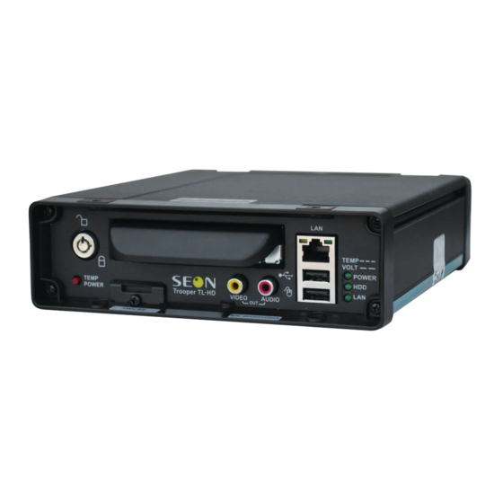
Contact Seon before attaching the DVR to other equipment in the vehicle. The TL-HD DVR is secured with a security front cover and a cable cover. The cable cover allows wiring to enter from the under side of the back of the unit. -
Page 9: Dimensions
[178] [266] 8 " [73] 4 " [134] 16 " 4 " [55] [19] 8 " 4 " [194] [120] 8 " [55] 8 " DIMENSIONS IN INCHES [MILLIMETRES IN BRACKETS] [98] Figure 1-1 Trooper TL-HD Dimensions 700-1014 R002 1–5... -
Page 10: Dvr And Component Installation
The hard disk drive is in a separate box in the system shipping kit. To install the TL-HD DVR: 1. Select an appropriate mounting location and orientation, horizontal or vertical. For the dimensions and location of the mounting holes, see Dimensions, on page 5. - Page 11 Installation 5. Fasten the mounting plate to the mounting surface with the four #10 × 1" self- drilling screws. 6. Connect the rear bottom edge of the DVR to the spring tab on the rear edge of the mounting tray. 7.
-
Page 12: Camera Installation
Installation 10. When DVR installation is complete, attach the front door by hooking the door along the top edge and turning the key to the locked position. Locking front cover Door lock 1.6.2. Camera Installation Install the cameras according to the product documentation that is included with the camera. - Page 13 Installation 4. Connect the Alarm Input harness connector to the ALARM socket on the DVR. Figure 1-2 Alarm Button and Alarm Input Harness 700-1014 R002 1–9...
-
Page 14: Adapter Harness Installation
Installation 1.6.4. Adapter Harness Installation To install the adapter harness: 1. Connect the 12-pin connector to the SIGNALS socket on the DVR. 2. Connect the 3-pin harness to the active high DVR wake signal (optional). 3. Connect the 5-pin to the Diagnostic Button or RGY Illuminator (optional). 4. -
Page 15: Sd Card Installation (Optional)
Installation 1.6.6. SD Card Installation (Optional) To install the SD Card: 1. On the front of the DVR, unscrew the screw holding the SD card cover plate and remove the cover plate. Figure 1-5 Remove SD card cover plate 2. Remove and discard the black plastic card slot sticker from behind the cover plate. Figure 1-6 Remove SD card slot sticker 700-1014 R002 1–11... - Page 16 Installation 3. Insert the Seon approved SD card in the slot, pushing it in firmly until a "click" is heard. Figure 1-7 Install SD card 4. If the DVR front locking cover is not being used, replace the cover plate and tighten the screw to hold it in place.
-
Page 17: Power Pass Through Cable Installation (Optional)
Installation 1.6.7. Power Pass Through Cable Installation (Optional) Use the power pass through cable to pass power to a device such as the Smart-Reach Cellular modem for communication with vMax Live Plus. The DVR Power Thru connector is not regulated and has a 2 Amp current rating. The power to the device is fused by the main DVR fuse. -
Page 18: Volt Installation Details
Installation 1.6.10. 12 Volt Installation Details CAUTION: Adverse operation of the DVR Seon does not recommend extending the power cable. Power drops created by additional wiring can cause adverse operation of the DVR. However, if a power cable extension is required, ensure that the voltage drop does not exceed 1.0 volt by using the correct cable size. -
Page 19: Hardware Installation Final Checklist
Installation 1.7. Hardware Installation Final Checklist Harnesses (camera, recorder, and accessories) Check that the cables and the harnesses are properly secured. Check that sharp metal edges are not touching the cables or harnesses. Check that the connections are solid (no shorts). ... - Page 20 Installation 1–16 700-1014 R002...
-
Page 21: Dvr Setup
Local access with On Screen Display (OSD) menus: Connect to VIDEO OUT on the TL-HD front panel with a portable video monitor and use a USB mouse to set the configuration settings. The password setting can be changed in the System Settings Menu. -
Page 22: Basic Dvr Configuration Settings
DVR Setup 2.2. Basic DVR Configuration Settings The DVR menu defaults cover most operation settings, but some basic customer and region-specific settings need to be configured for the DVR to operate optimally. Table 1 DVR Menu Configuration Requirements Menu Required Setting Select the date display format. - Page 23 DVR Setup On power-up, with a monitor and USB mouse connected to the DVR, the TL-HD splash screen appears briefly before the DVR enters live view. Figure 2-1 TL-HD Splash Screen During recording and live viewing, the screen information is dynamic and can include the items shown in Figure 2-2.
- Page 24 DVR Setup 2. In the Configuration menu, click Time/Date. Figure 2-4 Configuration Main Menu Note: To enter data in OSD fields, click with the mouse to display a keyboard. Use the on screen popup keyboard to select letters or numbers to input to fields. Examples are shown in Figure 2-5.
- Page 25 DVR Setup 3. In the Time and Date menu, select the following fields to show time and date for the video overlays: Time Format: Choose 12 or 24 hour time display format. Time: Input the correct time. Date Format: Select the date format.
- Page 26 DVR Setup 7. In the Monitor Settings menu, select options to provide monitor display for the camera output. Default Setting: Choose a monitor view setting which will display all the cameras you have connected. Display Switch: Leave On to switch the display as per the following settings.
- Page 27 DVR Setup 11. In the Record menu, set up record and power delay timers. Repeat Record: Leave at default for the hard drive to loop and record over the first recordings when it is full. Record Delay On Time: This sets the time period from when ignition is turned on until the DVR starts.
- Page 28 DVR Setup CAUTION: Set Unused Cameras Off When a DVR is installed with less than the full complement of cameras connected, disable unused camera input settings to prevent the DVR from generating Video Loss (VLoss) events for those camera inputs. In the DVR Configuration menus, disable unused camera inputs as follows: •...
- Page 29 DVR Setup 16. In the Configuration menu, click Alarm/Signal. 17. In the Alarms and Signals menu, click Alarms. CAUTION: Select Menu Options for Each Alarm From the Alarm drop down list, when any alarm (ALM 1, ALM 2, ALM3, or ALM 4) is selected, ALL of the settings on the Alarm Settings menu must be configured for that alarm.
- Page 30 18. In the Alarms and Signals menu, click Signals. Label: For signals 1-5, labels are provided for left turn, stop, brake, warning light, and right turn. The labels can be edited and changed, maximum 3 characters. Signals 6-10 are available for advanced signal wiring if required.
- Page 31 DVR Setup 20. In the Alarms and Signals menu, click GPS. GPS Display: If a GPS receiver is installed, select On to display the coordinates on the play view overlay. GPS Time: Select On to have the play view overlay time set by the GPS.
- Page 32 DVR Setup 21. In the Alarms and Signals menu, click G Sensor. Current: Display only, shows current live readings. Threshold: Seon recommends the following G Sensor threshold defaults for large bus movement detection. X and Y thresholds: +2.0 and -2.0. Z threshold: +3.0 and -3.0.
- Page 33 DVR Setup 23. In the Configuration menu, click Network to edit the DVR network settings. CAUTION: Network and Advanced Settings Network and Advanced network settings should only be configured by Seon Engineering Services or the fleet system administrator. Setting Type: Leave at default Static IP setting.
- Page 34 DVR Setup 25. In the Configuration menu, click System and in System Settings menu, configure as follows. Disk Full, HD Failure: Leave Off unless your network is configured to receive emails from the DVR. Password Enable: Leave Off unless instructed otherwise. Audio Output Channel: Select the default audio channel that will be available from the audio RCA port...
-
Page 35: Vmax Web Laptop Configuration
DVR Setup 2.3. vMax Web Laptop Configuration The TL-HD DVR can be managed using vMax Web using Internet Explorer (32 bit version only) with the laptop connected to the DVR using an RJ-45 Ethernet cable. Make sure the DVR and other system components are already installed and configured in order to access the DVR via vMax Web. - Page 36 DVR Setup The Local Area Connection Properties window appears. Figure 2-25 Local Area Connection Properties window 3. In the Local Area Connection Properties window, select the click to highlight the current Internet Protocol Version, (in Windows XP select Internet Protocol (TCP/IPv4)), and then click Properties.
-
Page 37: Connecting The Dvr To The Laptop
DVR Setup 2.3.1. Connecting the DVR to the Laptop To connect the DVR to the laptop: 1. Connect one end of the Ethernet cable to a network port on the laptop. Connect the other end to a network port on the DVR. 2. - Page 38 DVR Setup 5. Open Internet Explorer and, in the address bar, type in the DVR default IP address: http://169.254.1.1. Click Enter. The DVR Login screen appears. Figure 2-29 DVR Login Screen 6. At the login prompt, enter the user name and password to access the internet browser user interface.
-
Page 39: Advanced Setup
Advanced Setup HAPTER Advanced Setup This chapter provides information on uploading configuration files and firmware updates to the DVR, and setting up email notifications when events are detected on the DVR. CAUTION: Administrator Permissions Required These procedures should only be performed by administrator level staff. If you have questions about these procedures, contact Seon support. -
Page 40: Dvr Configuration Uploads
To load a configuration update to the DVR, the USB memory device must be formatted by a Windows-based computer using the FAT file format. To upload a configuration update on the TL-HD via USB: 1. Copy the configuration file at the root of the USB memory device folder. - Page 41 Advanced Setup 6. In the System Settings menu click Program Update. Figure 3-2 System Settings Menu 7. From the Load Configuration menu, select the file to upload and click Load. Figure 3-3 Loading USB Configuration The Load Configuration drop down list only displays the ten most recent Important: configuration files on the USB drive.
- Page 42 Advanced Setup 8. From Include Network, select whether or not to overwrite the existing DVR network settings with the new configuration settings. The default setting of NO keeps your existing network settings. CAUTION: DVR Communication Disruption Risk Avoid unintentionally changing the DVR network settings when uploading a new configuration.
- Page 43 Advanced Setup 10. In the DVR configuration confirmation dialog, click Yes to proceed. Figure 3-6 Load Configuration: Warning Message 11. Click Back in the Program Update and then System Settings menus to save and exit the menus. Figure 3-7 Click Back to Save Configuration 12.
-
Page 44: Configuration Uploads In Vmax Web
DVR and with Internet Explorer 8, 9, or 10 (32 bit version only) to access vMax Web. To upload a configuration update to the TL-HD via vMax Web: 1. On a computer connected to the DVR, copy the DVR configuration file. - Page 45 Advanced Setup 7. Select the Configuration tab and on the Configuration tab, click the System icon. Figure 3-11 vMax Web System Settings 8. In the Program Update Settings area, the default (cleared) Include Network Settings check box setting keeps your existing network settings during the configuration upload.
- Page 46 Advanced Setup 10. In the computer file search window, navigate to the configuration file and click Open. Figure 3-14 Windows File Search For consistency, Seon recommends that the configuration upload file name Important: should be kept to four characters maximum (****.seon) in the event that the file needs to be loaded to the DVR from the USB port.
- Page 47 Advanced Setup 14. When the progress bar shows the update is 100% complete, click OK. Figure 3-17 Loading Complete 15. In the Titles/Display menu, update the text in the Main_Title field. Figure 3-18 vMax Web Titles and Display Menu 16. Click Save to save the settings to the DVR. 17.
-
Page 48: Dvr Firmware Updates
Do not crank the vehicle power or remove the power while updating the DVR firmware. Equipment damage may result. To install a firmware update on the TL-HD DVR: 1. Load the Program Update file onto the USB memory device formatted by a Windows®-based computer using the FAT file format. -
Page 49: Email Notifications
Advanced Setup 3.3. Email Notifications If required by the customer, Seon DVRs can be configured to send emails when certain events are recorded. An SMTP server is required to support network email addresses. When the DVR is in range of a network, an email will be sent, the alarm recording can be viewed remotely, and the event can be addressed. - Page 50 Advanced Setup 5. In the E-mail settings menu, populate the E-mail configuration fields as required. Figure 3-22 E-mail Settings Menu 6. Click Back to save. 7. In the System Settings menu set the Disk Full and HD Failure options to E-mail. Figure 3-23 System Settings Menu 8.
- Page 51 Advanced Setup 10. In the Alarm/Signal menu, click Alarms. Figure 3-25 Alarms and Signals Menu 11. In the Alarm Settings menu, select the alarm from the drop down list, and set Email to On. Figure 3-26 Alarms Settings Menu 12. Repeat for all alarms requiring email notification. 13.
-
Page 52: Vmax Web Email Setup
Advanced Setup 3.3.2. vMax Web Email Setup 1. In the Network Email settings window, populate the E-mail configuration fields as required. vMax Web E-mail settings Figure 3-27 CAUTION: DVR Password Security The default password is 11111111. For security purposes, Seon recommends that the user default login and system settings passwords should be changed. - Page 53 Advanced Setup 3. In the System menu, select E-mail from the Disk Full and HD Failure drop down menus. System Settings Email Figure 3-29 4. Click Save. If the configured alarm or system events occur, the email will be sent when the DVR is within range of a Smart-Reach access point.
- Page 54 Advanced Setup 3–16 700-1014 R002...
-
Page 55: Dvr Configuration Menus
DVR Configuration Menus HAPTER DVR Configuration Menus This chapter describes the functions and defaults of the fields and options on each configuration menu. This chapter contains the following sections: DVR Configuration Menu Tree, on page 4–2 Time and Date Menu, on page 4–3 DST (Daylight Savings Time) Settings Menu, on page 4–4 Titles and Display Menu, on page 4–5 Monitor Settings Menu, on page 4–6... -
Page 56: Dvr Configuration Menu Tree
DVR Configuration Menus 4.1. DVR Configuration Menu Tree The TL-HD Configuration Main Menu shown in Figure 4-1 applies to the on screen display configuration and to the Web browser configuration menus. Trooper TL-HD DVR Configuration Main Menu Time/Date Record Alarm/Signal... -
Page 57: Time And Date Menu
DVR Configuration Menus 4.2. Time and Date Menu Use the Time and Date menu to set the time and date settings and Auto Daylight Savings settings. Figure 4-2 Time and Date Menu Table 1 Time and Date Configuration Items Menu Item Description Values [Default] Time Format... -
Page 58: Dst (Daylight Savings Time) Settings Menu
DVR Configuration Menus 4.2.1. DST (Daylight Savings Time) Settings Menu Configure the start and end date settings for daylight savings. Figure 4-3 DST Settings Menu Table 2 DST Settings Configuration Items Menu Item Description Values [Default] Start Date Set the week, day, and month for daylight saving to [2nd Sunday Mar] start. -
Page 59: Titles And Display Menu
DVR Configuration Menus 4.3. Titles and Display Menu Use the Titles and Display menu to set the main title, camera titles, and other camera view overlay options. Figure 4-4 Titles and Display Menu Table 3 Titles and Display Configuration Items Menu Item Description Value [Default]... -
Page 60: Monitor Settings Menu
DVR Configuration Menus 4.3.1. Monitor Settings Menu Use the Monitor Settings menu to set monitor default and switched views. Figure 4-5 Diagnostic Display Menu Table 4 Diagnostic Display Configuration Items Menu Item Description Value [Default] Default Setting Select the default monitor display setting, all [4 Up], CH1 - CH4 cameras or a single camera. -
Page 61: Diagnostic Display Menu
DVR Configuration Menus 4.3.2. Diagnostic Display Menu Use the Diagnostic Display menu to set various diagnostic options to display on the camera view overlays. Figure 4-6 Diagnostic Display Menu Table 5 Diagnostic Display Configuration Items Menu Item Description Value [Default] Voltage Display Display the system input voltage. -
Page 62: Health Check Menu
DVR Configuration Menus 4.3.3. Health Check Menu The Health Check screen provides information on the hard drive temperature, hard drive operational hours, Ethernet connections, and general health. Figure 4-7 Health Check Menu Table 6 Diagnostic Display Configuration Items Menu Item Description Value [Default] C (Celsius), Off... -
Page 63: Recording Menu
DVR Configuration Menus 4.4. Recording Menu Use the Recording Settings menu to set the resolution, recording speed in frames per second (FPS), image quality, Record Delay-On and Record Delay-Off times, and other recording options. Figure 4-8 Recording Settings Menu Table 7 Record Configuration Items Menu Item Description Value [Default]... -
Page 64: Camera Menus
Menu Item Description Value [Default] Speed Set the recording frame rate. The TL-HD has a maximum total Off, 1, 5, 7.5, 10, combined frame rate of 120 frames per second which can be [15], 30 fps distributed between up to 4 analog cameras. -
Page 65: Timer Menu
DVR Configuration Menus 4.4.2. Timer Menu Use the Timer Settings menu to set the timer schedules to turn the recording on and off. The timer function can only operate when the ignition is on. It cannot be set to record when the vehicle is off. -
Page 66: Hd Camera Menu
Depending on the mode selected, select a recording Record: 1, 2, [3], 4 quality for the camera. When Record2 mode is Record2: 1, [2], 3 selected, 3 is the maximum recording quality available. See Estimated Recording Time tables in the TL-HD User Guide. Audio Not available. [Off] Test Camera Click to test camera connection. -
Page 67: Hd Camera Advanced Menu
DVR Configuration Menus 4.4.4. HD Camera Advanced Menu The Advanced Settings menu is used to change the HD camera‘s IP subnet address. These IP settings should only be changed if the HD camera subnet conflicts with the DVR network subnet. If the IP address in this menu is edited, the IP address stored on the camera must be similarly changed. -
Page 68: Alarms And Signals Menu
DVR Configuration Menus 4.5. Alarms and Signals Menu Use the Alarms and Signals menu to set the options and actions that occur when an external alarm is received by the DVR. Usually, a driver-activated switch or other external device causes the alarm. Figure 4-13 Alarms and Signals Menu 4–14 700-1014 R002... -
Page 69: Alarm Menu
DVR Configuration Menus 4.5.1. Alarm Menu Select an alarm (1-4) from the menu and configure it as required. Figure 4-14 Alarm Settings Menu Table 12 Alarm Settings Configuration Items Menu Item Description Value [Default] Alarm ALM 1 to ALM 4 are available. [ALM 1], ALM 2, ALM 3, ALM 4 Alarm... -
Page 70: Signals Menu
DVR Configuration Menus 4.5.2. Signals Menu Use the Signals menu to configure signals and the actions they generate. The TL-HD supports 10 independent signals. The first five are designated as follows: LT (left turn signal), STP (stop), BRK (brake), WRN (warning lights), and RT (right turn signal). -
Page 71: Speed Menu
DVR Configuration Menus 4.5.3. Speed Menu Use the Speed Settings menu to set the options for recording vehicle speed data. Figure 4-16 Speed Settings Menu Table 14 Speed Settings Configuration Items Menu Item Description Value [Default] Speed Units The desired speed display units must be selected. Selecting [MPH] - Miles per MPH converts the GPS signal to display speed in miles per hour... -
Page 72: Gps Menu
DVR Configuration Menus 4.5.4. GPS Menu Use the GPS Settings menu to set the options for recording vehicle time and location data. Figure 4-17 GPS Settings Menu Table 15 GPS Settings Configuration Items Menu Item Description Value [Default] GPS Display Show or hide the GPS display on the main screen overlay. -
Page 73: G Sensor Menu
DVR Configuration Menus 4.5.5. G Sensor Menu Use the G Sensor Settings menu to set the options for recording vehicle acceleration, deceleration, and lateral motion data. • X – Forward/Back axis, default setting: +2.0/-2.0. • Y – Left/Right axis, default setting: +2.0/-2.0. •... -
Page 74: G Sensor Calibrate Menu
DVR Configuration Menus 4.5.6. G Sensor Calibrate Menu When the G Sensor threshold data is to be used, the DVR must be field calibrated. Based on the installation orientation selected in the G Sensor calibration menu, the DVR detects gravity and determines the X, Y, and Z axis orientations. To calibrate the G Sensor: 1. -
Page 75: Others Menu
DVR Configuration Menus 4.5.7. Others Menu In the Others menu, set DVR wake inputs and digital outputs. Wake On Input: Select if requested. Digital Output: Select if requested. Click Back to save the menu settings. Figure 4-20 Others Settings Menu Table 17 Others Menu Items Menu Item Description Value [Default]... -
Page 76: Network Menu
DVR Configuration Menus 4.6. Network Menu The TL-HD DVR has three Ethernet ports for connecting to a computer, HD camera, and Smart-Reach Lite wireless network equipment. See Installation Diagram, on page 1–3. CAUTION: Network Configuration To connect using the network connection, each host (computer) connected to the network must have a unique IP address. -
Page 77: Advanced Network Menu
DVR Configuration Menus 4.6.1. Advanced Network Menu Use to enable the DVR for live video streaming and vehicle tracking in vMax Live Plus. CAUTION: Advanced Settings Configuration For advanced settings, a qualified IT administrator is required to perform any configuration including assigning IP addresses. A cellular modem or gateway must also be installed and configured. -
Page 78: Vms Servers Menu
DVR Configuration Menus 4.6.2. VMS Servers Menu Set up to enable communication with Seon vMax Commander software. Figure 4-23 VMS Servers Menu Table 20 VMS Servers Configuration Items Menu Item Description Value [Default] Heartbeat Select an interval as determined by a qualified network expert, to [Off], 1, 2, 3, 4, 5 Interval transmit DVR status messages to all available VMS Servers every... -
Page 79: Supervisor Menu
DVR Configuration Menus 4.6.3. Supervisor Menu Set up to enable supervisor users in wireless environments. Figure 4-24 Supervisor Menu Set up to enable supervisor users in wireless environments. Table 21 VMS Servers Configuration Items Menu Item Description Value [Default] Supervisor Select Static IP to add a supervisor vehicle DVR’s Static IP [Off], Static IP Address to the Ethernet port. -
Page 80: User Levels Menu
DVR Configuration Menus 4.6.4. User Levels Menu Set up to enable multiple users to access the DVR from vMax Web View with various permission levels. Figure 4-25 User Levels Menu CAUTION: DVR Password Security The default password is 11111111. For security purposes, Seon recommends that the user default login and system settings passwords should be changed. -
Page 81: Ddns (Dynamic Domain Name Server) Menu
DVR Configuration Menus 4.6.5. DDNS (Dynamic Domain Name Server) Menu Use this menu to assign a specific host name to a DVR which is using a DHCP IP address. Figure 4-26 DDNS Settings Menu Table 23 DDNS Settings Configuration Items Menu Item Description Value [Default]... -
Page 82: System Menu
DVR Configuration Menus 4.7. System Menu The System Settings menu allows control of system level settings and functions that should only be accessed by authorized individuals. CAUTION: DVR Password Security The default password is 11111111. For security purposes, Seon recommends that the user default login and system settings passwords should be changed. -
Page 83: Program Update Menu
DVR Configuration Menus 4.7.1. Program Update Menu The Program Update menu enables users to update the internal firmware and to store and load the DVR configuration. Figure 4-28 Program Update Menu Table 25 Program Update Configuration Items Menu Item Description Value [Default] Load Load the configuration settings from a USB device. - Page 84 DVR Configuration Menus Figure 4-29 Load Configuration: Warning Message Figure 4-30 Store DVR Configuration to USB Device Message Figure 4-31 Update DVR Firmware Message 4–30 700-1014 R002...
- Page 85 DVR Configuration Menus Figure 4-32 Formatting the Hard Drive Message 700-1014 R002 4–31...
-
Page 86: E-Mail Menu
DVR Configuration Menus 4.7.2. E-mail Menu The E-mail Settings feature requires network connectivity. See Network Menu, on page 4–22. Figure 4-33 Email Settings Menu Table 26 Email Settings Configuration Items Menu Item Description Value [Default] SMTP Server Set the server name. Maximum 32 characters SMTP Port Set the SMTP port. -
Page 87: Legal Notice
Seon Design Inc. Trademarks Seon Design Inc. holds the following trademarks: Rogue™, Rogue™ Plus, Explorer™, and Trooper® are registered trademarks of Seon Design Inc. “Seon Design” is a registered trademark of Seon Design Inc. The Seon logo ( ) is a registered trademark of Seon Design Inc. - Page 88 L–2...
-
Page 89: Seon Design Inc.® Product Warranty
Three (3) years from date of purchase, parts and repair labor on all Cameras • Three (3) years from date of purchase, parts and repair labor on the Explorer® Premier, DX, TX, EX, MX, and Trooper® TL series mobile DVR Systems •... -
Page 90: Disclaimer
Seon Design Inc.® Product Warranty (g) if the product has been operated outside of the specified Operating Environment specified in the Seon User’s Manual for such product, or (h) to cover any costs incurred by the customer for the removal of defective cameras or components or of non-defective cameras or components, or for the installation of repaired cameras or components or for the reinstallation of non-defective cameras or components, all of which are for the account of the customer. - Page 91 The information contained herein is subject to change without notice. Extended Warranty for Certain Products The following extended warranty (“Extended Warranty”) provisions apply to products (“Extended Warranty Products”) in re spect of which the customer has purchased the Extended Warranty as a separate product from Seon. If any provisions of the Exte nded Warranty conflict or are inconsistent with the provisions of the basic warranty set forth above, the provisions of the Extended Warranty shall govern.
- Page 92 Seon Design Inc.® Product Warranty W–4 700-1014 R002...
- Page 94 Seon Design Inc. Unit 111, 3B Burbidge Street Coquitlam, BC Canada V3K 7B2 Telephone 604.941.0880 Toll Free Telephone 1.877.630.7366 604.941.0870 Toll Free Fax 1.866.664.3677 Email sales@seon.com Web site www.seon.com 700-1014 R002 Printed in Canada...
Need help?
Do you have a question about the TL-HD and is the answer not in the manual?
Questions and answers