
Related Manuals for SEON Explorer HX16


Summary of Contents for SEON Explorer HX16
- Page 1 Explorer HX16 Install and Setup Guide HX16 *700-1047* Document Part Number: 700-1047 R1 1.877.630.SEON www.seon.com...
- Page 2 Universal Serial Bus MPEG Moving Picture Experts Group UTC Universal Time Coordinated Finding Information Online You can find more information about Seon Design Inc. as well as its products and services at www.seon.com. Customer Service Contact Information Toll free telephone:1-877-630-7366 Telephone: 604-941-0880...
-
Page 3: Table Of Contents
1.2. Explorer HX16 System Components - - - - - - - - - - - - - - - - - - - - - - - - - - - - - - - - - - - - - - - - 1–2... - Page 4 Seon Design® Inc. - - - - - - - - - - - - - - - - - - - - - - - - - - - - - - - - - - - - - - - - - - - - - - - - - - - - - - - - L–1...
-
Page 5: Tools And Equipment
Installation HAPTER Installation This chapter describes the installation steps for the Explorer HX16 DVR. This chapter contains the following sections: Tools and Equipment, on page 1–1 Explorer HX16 System Components, on page 1–2 Installation Diagram, on page 1–3 Installation Best Practices, on page 1–4 Dimensions, on page 1–5... -
Page 6: Explorer Hx16 System Components
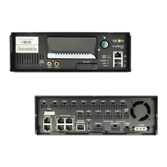
The typical installation components are shown below. The actual contents of your installation package may vary, depending on the options selected. Explorer HX16 DVR with hard drive, Cameras (up to 16, including 4 802.3af HD cameras) and extension cables locking front cover, cable cover, fasteners,... -
Page 7: Installation Diagram
An optional Video Monitor can be used from the video outputs located on the front or back panel. 12V 150mA source or 0V 350mA sink Wake up input, active high (5 - 32V edge triggered) Use Seon approved cards only Figure 1 Typical HX16 System 700-1047 R1... -
Page 8: Installation Best Practices
Route the wiring and cables away from sharp edges that might damage the insulation. Avoid sharp bends in the cable. Contact Seon before attaching the DVR to other equipment in the vehicle. The HX16 DVR is secured with a security front cover and a cable cover. The cable cover allows wiring to enter from the under side of the back of the unit. -
Page 9: Dimensions
Important: Specifications are subject to change without notice. • Weight: 13.0 lb (5.9 kg) including covers and mounting plate • Material: steel base, aluminum housing, plastic " " " " " 7" " " " Figure 1-1 Explorer HX16 Dimensions 700-1047 R1 1–5... -
Page 10: Dvr And Component Installation
Installation 1.6. DVR and Component Installation 1.6.1. DVR Installation The DVR typically ships with the locking front cover, mounting plate, and cable cover off but in the shipping box. The hard disk drive is in a separate box in the system shipping kit. - Page 11 Installation 7. Attach the cable cover to the DVR using the provided thumb screws. Thumb screws Cable Cover 8. Insert a hard drive inside the DVR and lock the HDD drive. DVR hard drive SD card input 9. Install optional SD card if used. See SD Card Installation (Optional), on page 1–9. 10.
-
Page 12: Camera Installation
Installation 1.6.2. Camera Installation Install the CA and CQ series analog and CHW8PD and CHQ8PD series high definition cameras according to the installation guides included with the camera. 1.6.2.1. Back Light Compensation To enable back light compensation in the CHW8PD and CHQ8PD series high definition cameras, see the DVR Configuration >... -
Page 13: Expansion Harness Installation (Optional)
1. On the front of the DVR, unscrew the screw holding the SD card cover plate and remove the cover plate. Figure 1-4 Remove SD card cover plate 2. Insert the Seon approved SD card in the slot, pushing it in firmly until a "click" is heard. 700-1047 R1... -
Page 14: Diagnostic Button Installation (Optional)
700-0139. 1.6.8. 12 Volt Power Cable Extension Details Seon does not recommend extending the power cable. Power drops created by additional wiring can cause adverse operation of the DVR. However, if a power cable extension is required, ensure that the voltage drop does not exceed 1.0 volt. -
Page 15: Hardware Installation Final Checklist
Installation 1.7. Hardware Installation Final Checklist Harnesses (camera, recorder, and accessories) Check that the cables and the harnesses are properly secured. Check that sharp metal edges are not touching the cables or harnesses. Check that the connections are solid (no shorts). ... - Page 16 Installation 1–12 700-1047 R1...
-
Page 17: Dvr Basic Setup
DVR to be on the same subnet as the laptop. Remote access with vMax Web menus: If you have Seon Smart Reach wireless access, you can also access the DVR remotely using vMax Web via Internet Explorer (32 bit version only). -
Page 18: Basic Dvr Configuration Settings
DVR Basic Setup 2.2. Basic DVR Configuration Settings Once the unit is installed and power and cabling settings are complete, set up the DVR in the configuration menus. For a complete description of all available menu options, see DVR Configuration Menu Tree, on page 4-2. - Page 19 DVR Basic Setup On power-up, with a monitor and USB mouse connected to the DVR, the HX16 splash screen appears briefly before the DVR enters live view. Figure 2-1 HX16 Splash Screen During recording and live viewing, the screen information is dynamic and can include the items shown in Figure 2-2.
- Page 20 DVR Basic Setup 2. In the Configuration menu, click Time/Date. Figure 2-4 Configuration Main Menu Note: To enter data in OSD fields, click with the mouse to display a keyboard. Use the on screen popup keyboard to select letters or numbers to input to fields. Examples are shown in Figure 2-5.
- Page 21 DVR Basic Setup 3. In the Time and Date menu, select the following fields to show time and date for the video overlays: Time Format: Choose 12 or 24 hour time display format. Time: Input the correct time. Date Format: Select the date format.
- Page 22 DVR Basic Setup 7. In the Monitor Settings menu, select options to provide monitor display for the camera output. Front Default Setting/Rear Default Setting: Choose a monitor view setting which displays all the cameras you have connected. The Front setting applies to video output via the RCA jack on the DVR front panel;...
- Page 23 DVR Basic Setup 11. In the Record menu, set up record and power delay timers. Repeat Record: Leave at default for the hard drive to loop and record over the first recordings when it is full. Record-On Delay Time: This sets the time period (0 seconds to 1 hour) from when ignition is turned on until the DVR starts.
- Page 24 DVR Basic Setup Figure 2-11 Camera Settings Menu New titles will display here as well as in the play view overlays. Title: Select camera titles that reflect the views they are recording. Sample titles: • Front • Step • • Rear •...
- Page 25 DVR Basic Setup 13. In the Recording Settings menu, click Timers only if you have a specific requirement for timers. Leave the Enable Timers setting set to Off, unless instructed otherwise and provided specific start and end timer information. The timer function can only operate when the ignition is on.
- Page 26 DVR Basic Setup 16. In the Alarms and Signals menu, click Signals. Label: For signals 1-7, labels are provided for left turn, stop, brake, warning light, and right turn. The labels can be edited and changed, maximum 3 characters. Level: Set all signal levels as required. Choose Active High if the circuit you are installing into rests at 0 VDC and goes to 12 VDC when active.
- Page 27 DVR Basic Setup 18. In the Alarms and Signals menu, click GPS. Fencing Alarm: Select alarm if required. Coordinate Style: Select Circle or Rectangle if required. Click Back to save the menu settings. Format the drive after GPS settings are complete. Figure 2-16 GPS Settings Menu SETUP TIP: Recording over Multiple GPS UTC Reference Settings...
- Page 28 DVR Basic Setup 19. In the Alarms and Signals menu, click G Sensor. Current: Display only, shows current live readings. Threshold: Seon recommends the following G Sensor threshold defaults for large bus movement detection. X (forward) and Y (lateral) thresholds: +2.0 and -2.0.
- Page 29 21. In the Configuration menu, click Network to edit the DVR network settings. SECURITY TIP: Network and Advanced Settings Network and Advanced network settings should only be configured by Seon Engineering Services or the fleet system administrator. Setting Type: Leave at default DHCP setting.
- Page 30 Figure 2-20 User Levels Menu SECURITY TIP: DVR Password Security The default password is 11111111. For security purposes, Seon recommends that the user default login and system settings passwords should be changed. Keep a copy of your password in a secure place in case it is lost or forgotten.
- Page 31 DVR Basic Setup 24. In the System Settings menu, click Program Update and in the Program Update menu, store the DVR configuration as a file to upload to other DVRs. Select USB Device as the file saving destination. Plug a USB memory device into the front of the DVR.
-
Page 32: Vmax Web Laptop Configuration
DVR Basic Setup 2.3. vMax Web Laptop Configuration The HX16 DVR can be managed by vMax Web using Internet Explorer (32 bit version only) with the laptop connected to the DVR using an RJ-45 Ethernet cable. Make sure the DVR and other system components are already installed and configured in order to access the DVR via vMax Web. - Page 33 DVR Basic Setup The Local Area Connection Properties window appears. Figure 2-24 Local Area Connection Properties window 3. In the Local Area Connection Properties window, select the click to highlight the current Internet Protocol Version, (in Windows XP select Internet Protocol (TCP/IPv4)), and then click Properties.
-
Page 34: Connecting The Dvr To The Laptop
DVR Basic Setup 2.3.1. Connecting the DVR to the Laptop To connect the DVR to the laptop: 1. Connect one end of the Ethernet cable to a network port on the laptop. Connect the other end to a network port on the DVR. 2. - Page 35 The user name is case sensitive. SECURITY TIP: DVR Password Security The default password is 11111111. For security purposes, Seon recommends that the user default login and system settings passwords should be changed. Keep a copy of your password in a secure place in case it is lost or forgotten.
- Page 36 DVR Basic Setup 8. When accessing the HX-16 DVR for the first time, install the ePlayer.exe by following the steps displayed. SETUP TIP: PC Download Security Windows security may block running the ePlayer.exe. Ensure your PC security settings are configured to enable downloading and installing this file Figure 2-29 Download ePlayer 9.
- Page 37 DVR Basic Setup 10. Select the default destination and click Next. Figure 2-31 ePlayer Setup Wizard 2 11. In the ePlayer Setup wizard, click Install. Figure 2-32 ePlayer Setup Wizard 3 12. In the ePlayer Setup prompt, click Yes. Figure 2-33 ePlayer Setup Prompt 700-1047 R1 2–21...
- Page 38 DVR Basic Setup 13. In the ePlayer Setup wizard, click Next. Figure 2-34 ePlayer Setup Wizard 4 14. After the progress bar completes, click Finish. Figure 2-35 ePlayer Setup Wizard 5 15. Launch Internet Explorer and reload the DVR webpage. 2–22 700-1047 R1...
- Page 39 DVR Basic Setup vMax Web opens with the DVR cameras displaying in Live view. Figure 2-36 vMax Web Live View 16. See Advanced Setup, on page 3-1 and the DVR User manual for details on using vMax Web to view, configure, playback, and archive video from the DVR. 700-1047 R1 2–23...
- Page 40 DVR Basic Setup 2–24 700-1047 R1...
-
Page 41: Advanced Setup
DVR. SECURITY TIP: Administrator Permissions Required These procedures should only be performed by administrator level staff. If you have questions about these procedures, contact Seon support. This chapter contains the following sections: DVR Configuration Uploads, on page 3–2 Configuration Upload from USB Memory Device, on page 3–2 Configuration Uploads in vMax Web, on page 3–7... -
Page 42: Dvr Configuration Uploads
1. Copy the configuration file at the root of the USB memory device folder. Important: For USB uploading, the configuration file name can have no more than four characters. Example: TLHD.seon. 2. Power up the DVR using the vehicle ignition. 3. Connect the portable video monitor and USB mouse. - Page 43 Advanced Setup 6. In the System Settings menu click Program Update. Figure 3-2 System Settings Menu 7. From the Load Configuration menu, select the file to upload and click Load. Figure 3-3 Loading USB Configuration Important: The Load Configuration drop down list only displays the ten most recent configuration files on the USB drive.
- Page 44 Advanced Setup 8. From Include Network, select whether or not to overwrite the existing DVR network settings with the new configuration settings. The default setting of NO keeps your existing network settings. SETUP TIP: DVR Communications Avoid changing the DVR network settings when uploading a new configuration. When saving or changing network settings, communication with the DVR can be disrupted.
- Page 45 Advanced Setup 10. In the DVR configuration confirmation dialog, click Yes to proceed. Figure 3-6 Load Configuration: Warning Message 11. Click Back in the Program Update and then System Settings menus to save and exit the menus. Figure 3-7 Click Back to Save Configuration 12.
- Page 46 Advanced Setup 16. Turn off the DVR, restart the DVR, and confirm that the new configuration settings have been applied. 3–6 700-1047 R1...
-
Page 47: Configuration Uploads In Vmax Web
Figure 3-9 DVR Login Screen SECURITY TIP: DVR Password Security The default password is 11111111. For security purposes, Seon recommends that the user default login and system settings passwords should be changed. Keep a copy of your password in a secure place in case it is lost or forgotten. - Page 48 Advanced Setup 7. Select the Configuration tab and on the Configuration tab, click the System icon. Figure 3-11 vMax Web System Settings 8. In the Program Update Settings area, the default (cleared) Include Network Settings check box setting keeps your existing network settings during the configuration upload.
- Page 49 Important: For consistency, Seon recommends that the configuration upload file name should be kept to four characters maximum (****.seon) in the event that the file needs to be loaded to the DVR from the USB port. The DVR USB upload interface supports only four characters in the file name.
- Page 50 Advanced Setup 14. When the progress bar shows the update is 100% complete, click OK. Figure 3-17 Loading Complete 15. In the Titles/Display menu, update the text in the Main_Title field. The Main Title is displayed on the Live View screen of vMax Web and the front panel video output.
-
Page 51: Dvr Firmware Updates
The firmware version is displayed on the top right corner of every menu. Firmware updates must be obtained from Seon Design. To install a firmware update, a USB memory device must be formatted by a Windows®-based computer using the FAT file format. -
Page 52: Smart-Stop Setup For Vmax Commander
Advanced Setup 3.3. Smart-Stop Setup for vMax Commander After a vehicle’s ignition is turned off, Smart-Stop reduces the DVR’s draw on the vehicle battery by shutting down the DVR as soon as it is no longer needed for video or data downloads by the network. This section describes how Smart-Stop works and how to set it up on the DVR. -
Page 53: If Vmax Commander Sends No Request To The Dvr
Advanced Setup 3.3.1.2. If vMax Commander Sends No Request to the DVR If vMax Commander does not send a Keep Alive On message during the Record-Off Delay or Smart-Stop times, the DVR powers off when the Smart-Stop timer is finished. Smart-Stop overrides the Power-Off Delay timer. vMax Commander does not send Ignition On Ignition Off... - Page 54 Advanced Setup 4. In the Recording Settings menu, select suitable Record-Off Delay, Smart-Stop, and Power-Off Delay timer durations, depending on your system requirements. To ensure enough time for network communication and downloads, Seon recommends the following settings: • Record-Off Delay: 10 min •...
-
Page 55: Event Recording Setup
Advanced Setup 3.4. Event Recording Setup Use Event Recording to have one or more cameras record only when an alarm is triggered on the DVR. Users can select the following configuration parameters: • a specific alarm or all alarms that will start Event recording. •... - Page 56 Advanced Setup 6. In the Camera Settings menu, set each required camera’s Event to On or Off. • On records using both R1 and R2 recording settings. The R1 setting is as selected in this menu, and R2 is selected in the Recording Settings > Record2 menu.
-
Page 57: Email Notifications
Advanced Setup 3.5. Email Notifications If required by the customer, Seon DVRs can be configured to send emails when certain events are recorded. An SMTP server is required to support network email addresses. When the DVR is in range of a network, an email will be sent, the alarm recording can be viewed remotely, and the event can be addressed. - Page 58 Advanced Setup 5. In the E-mail settings menu, populate the E-mail configuration fields as required. Figure 3-30 E-mail Settings Menu 6. Click Back to save. 7. In the System Settings menu set the Disk Full and HD Failure options to E-mail. Figure 3-31 System Settings Menu 8.
- Page 59 Advanced Setup 10. In the Alarm/Signal menu, click Alarms. Figure 3-33 Alarms and Signals Menu 11. In the Alarm Settings menu, select the alarm from the tabs, and set Email to On. Figure 3-34 Alarms Settings Menu 12. Repeat for all alarms requiring email notification. 13.
-
Page 60: Vmax Web Email Setup
Figure 3-35 SECURITY TIP: DVR Password Security The default password is 11111111. For security purposes, Seon recommends that the user default login and system settings passwords should be changed. Keep a copy of your password in a secure place in case it is lost or forgotten. - Page 61 Advanced Setup 3. In the System menu, select E-mail from the Disk Full and HD Failure drop down menus. System Settings Email Figure 3-37 4. Click Save. If the configured alarm or system events occur, the email will be sent when the DVR is within range of a Smart-Reach access point.
- Page 62 Advanced Setup 3–22 700-1047 R1...
-
Page 63: Dvr Configuration Menus
DVR Configuration Menus HAPTER DVR Configuration Menus This chapter describes the functions and defaults of the fields and options on each configuration menu. This chapter contains the following sections: DVR Configuration Menu Tree, on page 4–2 Time and Date Menu, on page 4–3 DST (Daylight Savings Time) Settings Menu, on page 4–4 Titles and Display Menu, on page 4–5 Monitor Settings Menu, on page 4–9... -
Page 64: Dvr Configuration Menu Tree
DVR Configuration Menus 4.1. DVR Configuration Menu Tree The HX16 Configuration Main Menu shown in Figure 4-1 applies to the on screen display configuration and to the Web browser configuration menus. HX16 Configuration Menu Time/Date Title/Display Record Alarms and Signals Network System Disk Full:... -
Page 65: Time And Date Menu
DVR Configuration Menus 4.2. Time and Date Menu Use the Time and Date menu to set the time and date and Daylight Savings time settings. Figure 4-2 Time and Date Menu Table 1 Time and Date Configuration Items Menu Item Description Values [Default] Daylight Saving... -
Page 66: Dst (Daylight Savings Time) Settings Menu
DVR Configuration Menus 4.2.1. DST (Daylight Savings Time) Settings Menu Configure the start and end date settings for daylight savings. Figure 4-3 DST Settings Menu Table 2 DST Settings Configuration Items Menu Item Description Values [Default] Start Date Set the week, day, and month for daylight saving to [2nd Sunday Mar] start. -
Page 67: Titles And Display Menu
DVR Configuration Menus 4.3. Titles and Display Menu Use the Titles and Display menu to set the main title, camera titles, and other camera view overlay options. Figure 4-4 Titles and Display Menu Table 3 Titles and Display Configuration Items Menu Item Description Value [Default]... -
Page 68: Diagnostic Display Menu
DVR Configuration Menus 4.3.1. Diagnostic Display Menu Use the Diagnostic Display menu to set various diagnostic options to display on the camera views as overlays. Figure 4-5 Diagnostic Display Menu Table 4 Diagnostic Display Configuration Items Menu Item Description Value [Default] HDD Size Display Display the hard drive size. -
Page 69: Health Check Menu - Hard Drive Tab
DVR Configuration Menus 4.3.2. Health Check Menu - Hard Drive Tab The Health Check menu’s Hard Drive tab provides information on the hard drive temperature, hours, and general health. Figure 4-6 Health Check Menu, Hard Drive tab Table 5 Health Check Menu, Hard Drive tab Configuration Items Menu Item Description Value [Default]... -
Page 70: Health Check Menu - Dvr Ethernet Tab
DVR Configuration Menus 4.3.3. Health Check Menu - DVR Ethernet Tab The Health Check menu’s DVR Ethernet tab provides status information on the DVR Ethernet ports. Camera titles display as entered in the Record > Camera Settings > HD Settings menu. •... -
Page 71: Monitor Settings Menu
DVR Configuration Menus 4.3.4. Monitor Settings Menu Use the Monitor Settings menu to set monitor default and switched views when a monitor is plugged into the DVR. Figure 4-8 Monitor Settings Menu Table 7 Monitor Settings Configuration Items Menu Item Description Value [Default] Front Default Setting... -
Page 72: Recording Menu
1, 5, 10, 20, auxiliary connector on the DVR rear panel. For more information, see 30, 45, 60 “PWR OUT” on page 1–7 in the Explorer HX16 User Guide. Record-Off Enables a time delay to continue recording after the ignition signal to... - Page 73 DVR Configuration Menus Table 8 Record Configuration Items Value Menu Item Description [Default] Record2 The DVR can record video in two streams, one at high resolution for [Off], 5FPS full detailed event information, and the other (Record2) at lower resolution for fast downloading or real-time viewing over a low bandwidth network, such as a cellular link.
-
Page 74: Camera Menus
DVR Configuration Menus 4.4.1. Camera Menus Use the Camera Settings menus to set the FPS, picture quality, recording resolution, and audio recording for up to 12 analog cameras and up to 4 HD cameras. Figure 4-10 Analog and HD Camera Settings Menus SETUP TIP: Set Unused Cameras Off When a DVR is installed with less than the full complement of cameras connected, disable unused camera input settings to prevent the DVR from generating Video Loss (VLoss) - Page 75 DVR Configuration Menus Table 9 Camera Settings Configuration Items Menu Item Description Value [Default] Event Enables the selected camera to record only when an event is Off, [On] triggered. On records using both R1 (high resolution) and R2 (low resolution) recording settings. The R1 setting is as selected in this menu, and R2 is selected in the Recording Settings >...
-
Page 76: Hd Advanced Menu
DVR network subnet. If the IP address in this menu is edited, the IP address stored on the camera must be similarly changed. Contact Seon Support if you wish to edit settings on this menu. SECURITY TIP: HD Camera Network Contact Seon Support if you wish to edit settings on this menu. -
Page 77: Timer Settings Menu
DVR Configuration Menus 4.4.3. Timer Settings Menu Use the Timer Settings menu to set the timer schedules to turn the recording on and off. The timer function can only operate when the ignition is on. It cannot be set to record when the vehicle is off. -
Page 78: Alarms And Signals Menu
DVR Configuration Menus 4.5. Alarms and Signals Menu Use the Alarms and Signals menu to set the options and actions that occur when an external alarm is received by the DVR. Usually, a driver-activated switch or other external device causes the alarm. Figure 4-13 Alarms and Signals Menu 4–16 700-1047 R1... -
Page 79: Alarm Menu
DVR Configuration Menus 4.5.1. Alarm Menu Select an alarm (1-4) from the menu tabs and configure it as required. Figure 4-14 Alarm Settings Menu Table 12 Alarm Settings Configuration Items Menu Item Description Value [Default] Duration The alarm duration is the length of time after an alarm has been 0, [5], 10, 30 sec, received that the video is recorded at the alarm speed, quality, 1, 3, 5, 10, 15, 20,... -
Page 80: Signals Menu
DVR Configuration Menus 4.5.2. Signals Menu Use the Signals menu to configure signals and the actions they generate. The HX16 supports 7 independent signals. The first five are designated as follows: LT (left turn signal), STP (stop), BRK (brake), WRN (warning lights), and RT (right turn signal). The last two can be set for other functions. -
Page 81: Speed Menu
DVR Configuration Menus 4.5.3. Speed Menu Use the Speed Settings menu to set the options for recording vehicle speed data. Figure 4-16 Speed Settings Menu Table 14 Speed Settings Configuration Items Menu Item Description Value [Default] Speed Units The desired speed display units must be selected. Selecting [MPH] - Miles per MPH converts the GPS signal to display speed in miles per hour... -
Page 82: Gps Menu
DVR Configuration Menus 4.5.4. GPS Menu Use the GPS Settings menu to set the options for recording vehicle time and location data. Figure 4-17 GPS Settings Menu Table 15 GPS Settings Configuration Items Value Menu Item Description [Default] Fencing (Geo- Using GPS, Geo-fencing lets the administrator set a [Off], ALM 1, fencing) Alarm... -
Page 83: G Sensor Menu
DVR Configuration Menus 4.5.5. G Sensor Menu Use the G Sensor Settings menu to set the options for recording vehicle acceleration, deceleration, and lateral motion data. • X – Forward/Back axis, default setting: +2.0/-2.0. • Y – Left/Right axis, default setting: +2.0/-2.0. •... -
Page 84: G Sensor Calibrate Menu
DVR Configuration Menus 4.5.6. G Sensor Calibrate Menu When the G Sensor threshold data is to be used, the DVR must be field calibrated. Based on the installation orientation selected in the G Sensor calibration menu, the DVR detects gravity and determines the X, Y, and Z axis orientations. To calibrate the G Sensor: 1. -
Page 85: Other Menu
DVR Configuration Menus 4.5.7. Other Menu In the Others menu, set DVR wake inputs and digital outputs. Figure 4-20 Others Settings Menu Table 17 Others Menu Items Menu Item Description Value [Default] Wake On Select the input action which will wake the DVR. Upon [Off], ALM 1, TEMP Input sensing a wake input (signals connector) if Wake On Input... - Page 86 DVR Configuration Menus Table 17 Others Menu Items Control Select to choose whether Power Delay-Off or Record [Power Delay Off], Output Off: Delay-Off settings (from the Record menu) will be used to Record Delay Off control the device that the DVR’s Control output is connected to.
-
Page 87: Network Menu
Network settings, Advanced Settings, and E-mail settings. Contact Seon Engineering Services or Technical Support to perform any configuration, assign an IP address, reset the Smart-Reach Mobile wireless bridge or operating information. -
Page 88: Advanced Network Menu
Figure 4-22 Advanced Network Settings Menu Set up to enable the DVR to simultaneously connect with cellular and Wi-Fi networks using a Seon Smart-Reach Cellular modem. See the Smart-Reach Cellular Install and Setup Guide, 700-1018, for details. Table 19 Advanced Network Configuration Items... -
Page 89: Vms Servers Menu
DVR Configuration Menus Table 19 Advanced Network Configuration Items Value Menu Item Description [Default] iVML Subnet Set the subnet mask for the iVML IP Address as determined by [24] Mask a qualified network expert. Use a value between 0 and 32. Default Enter the Default Gateway IP address as determined by a [172.30.2.1]... -
Page 90: Supervisor Menu
DVR Configuration Menus 4.6.3. Supervisor Menu Set up to enable supervisor users in wireless environments. Figure 4-24 Supervisor Menu Set up to enable supervisor users in wireless environments. Table 21 VMS Servers Configuration Items Menu Item Description Value [Default] Supervisor Select Static IP to add the static IP address of a supervisor [Off], Static IP vehicle’s DVR to the Ethernet port. -
Page 91: User Levels Menu
SECURITY TIP: DVR Password Security The default password is 11111111. For security purposes, Seon recommends that the user default login and system settings passwords should be changed. Keep a copy of your password in a secure place in case it is lost or forgotten. -
Page 92: Ddns (Dynamic Domain Name Server) Menu
DVR Configuration Menus 4.6.5. DDNS (Dynamic Domain Name Server) Menu Use this menu to assign a specific host name to a DVR which is using a DHCP IP address. Figure 4-26 DDNS Settings Menu Table 23 DDNS Settings Configuration Items Menu Item Description Value [Default]... -
Page 93: System Menu
SECURITY TIP: DVR Password Security The default password is 11111111. For security purposes, Seon recommends that the user default login and system settings passwords should be changed. Seon is not responsible if the password is lost or forgotten. Figure 4-27 System Settings Menu... -
Page 94: Program Update Menu
DVR Configuration Menus 4.7.1. Program Update Menu The Program Update menu enables users to update the internal firmware and to store and load the DVR configuration. Figure 4-28 Program Update Menu Table 25 Program Update Configuration Items Menu Item Description Value [Default] Load Load the configuration settings from a USB device. - Page 95 DVR Configuration Menus Figure 4-29 Load Configuration: Warning Message Figure 4-30 Store DVR Configuration to USB Device Message Figure 4-31 Update DVR Firmware Message 700-1047 R1 4–33...
- Page 96 DVR Configuration Menus Figure 4-32 Formatting the Hard Drive Message 4–34 700-1047 R1...
-
Page 97: E-Mail Menu
DVR Configuration Menus 4.7.2. E-mail Menu The E-mail Settings feature requires network connectivity. See Network Menu, on page 4–25. Figure 4-33 E-mail Settings Menu Table 26 E-mail Settings Configuration Items Menu Item Description Value [Default] SMTP Server Set the server name. Maximum 32 characters SMTP Port Set the SMTP port. - Page 98 DVR Configuration Menus 4–36 700-1047 R1...
-
Page 99: Seon Design Inc.® Product Warranty
Seon reserves the right to refund the purchase price or to issue a credit only in lieu of replacement. Seon may use new or refurbished replacement parts for repairing its products, at its sole and arbitrary discretion. -
Page 100: Disclaimer
Provisions Applicable to American Customers For those customers whose mailing address is in the United States, Seon’s offer and any agreement of sale resulting therefrom shall be governed by and construed in accordance with the internal and domestic laws of the State of WASHINGTON without giving effect to the conflict of laws rules thereof. - Page 101 RETURN AUTHORIZATION (RA) NUMBER. Seon will only be responsible for the cost of ground freight. Any additional costs for express modes of freight will be paid by the purchaser of the Extended Warranty Product.
- Page 102 Seon Design Inc.® Product Warranty W–4 700-1047 R1...
-
Page 103: Legal Notice
Design Inc. that are the property of their respective owners. They are used in this User Manual for identification purposes only. User Manual Revision This is the R1 revision for this User Manual and is copyright, June 2016 by Seon Design Inc. All rights reserved. Exclusion of Liability SEON DESIGN INC... - Page 104 L–2 700-1047 R1...
-
Page 106: Seon Design Inc
Seon Design Inc. Unit 111, 3B Burbidge Street Coquitlam, BC Canada V3K 7B2 Telephone 604.941.0880 Toll Free Telephone 1.877.630.7366 604.941.0870 Toll Free Fax 1.866.664.3677 Email sales@seon.com Web site www.seon.com 700-1047 R1 Printed in Canada...
Need help?
Do you have a question about the Explorer HX16 and is the answer not in the manual?
Questions and answers