Table of Contents
Advertisement
IMPORTANT NOTICE: Any alteration that is not approved by AGA,
could invalidate the approval of the appliance, the operation of the
warranty and could also affect your statutory rights.
Control of Substances - Health and Safety
Important
This appliance may contain some of the materials that are indicated
below. It is the Users/Installers responsibility to ensure that the
necessary personal protective clothing is worn when handling, where
applicable, the pertinent parts that contain any of the listed materials
that could be interpreted as being injurious to health and safety, see
below for information.
INTRODUCTION
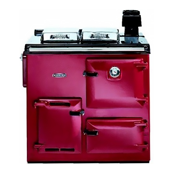
The Rayburn 200 G/L Cooker provides cooking facilities
only, and is suitable for Natural Gas. A single atmospheric
gas burner is thermostatically controlled at cooking rates,
and operates at a low bypass rate when idling.
The exhaust flue connection of the appliance is in Open
Flue form, operating on natural draught.
Facilities included on the cooker are, a heat graduated
hotplate, main oven and lower oven. A timing programmer
is also available, as an optional extra.
Technical Specification
Natural Gas
Heat Input
Pressure
Injector Size
Pilot Size
Propane
Heat Input
Inlet Pressure
Injector Size
Pilot Size
raywarranty@aga-web.co.uk
5.6kW
G20
20mbar
G25
25mbar
1.82 Bray 460
38/36A
20MJ/h
Propane 2.75 kPa
1.27 Bray 220
4209
Installation and Servicing Instructions
for Rayburn 200G/L
Gas Fired Cooker
Firebricks, Fluebeds, Artificial Fuels – when handling use
disposable gloves.
Fire cement – when handling use disposable gloves.
Glues and sealants – exercise caution – if these are still in liquid
form use face mask and disposable gloves.
Glass Yarn, Mineral Wool, Insulation Pads, Ceramic Fibre,
Kerosene Oil –may be harmful if inhaled. may be irritating to skin,
eyes, nose and throat. When handling avoid, inhaling and contact
with skin or eyes. Use disposable gloves, face-masks and eye
protection. After handling wash hands and other exposed parts.
When disposing of the product, reduce dust with water spray, ensure
that parts are securely wrapped.
INSTALLATION INSTRUCTIONS
Gas connection 15mm O.D. copper
Open flue outlet 100mm (4in. int)
Electric Supply 240V ~ 50Hz 3 amp fused
Weight of Appliance 275kg
Installation Instructions
The appliance must be installed in accordance with these
instructions, local gas fitting regulations, municipal
building codes, electrical wiring regulations, the AGA Gas
Installation Code and any other relevant statutory body.
In your own interests, and that of safety to comply with the
law, all gas appliances to be installed by authorised
persons, in accordance with the above regulations.
Failure to install appliances correctly could lead to
prosecution.
1
AUSTRALIAN MARKET
Certificate of Approval No. 5013
01/10 EINS 512070
Advertisement
Table of Contents

Related Manuals for Rayburn 200G/L Gas Fired Cooker


Summary of Contents for Rayburn 200G/L Gas Fired Cooker
-
Page 1: Technical Specification
INTRODUCTION INSTALLATION INSTRUCTIONS The Rayburn 200 G/L Cooker provides cooking facilities Gas connection 15mm O.D. copper only, and is suitable for Natural Gas. A single atmospheric Open flue outlet 100mm (4in. int) -
Page 2: Flue System
4” (100mm DIA C.I. FLUE 1245 GAS CONNECTION Fig. 1 FLUE SYSTEM Appliance The appliance must be installed on a solid level floor or base of incombustible material which is capable of Detailed recommendations for fluing are given in Fluing supporting the total weight. -
Page 3: Electrical Supply
Flue pipes which extend through the roof shall terminate Alternatively, a fused double-pole switch having contact no less than 500mm from the nearest part of the roof. separation of at least 3mm in both poles serving only the appliance may be used. Before connecting the appliance to or inserting a liner into, a flue that has been previously used the flue must be The point of connection to the mains should be readily... -
Page 4: Installation
Preliminary Installation The appliance is delivered assembled with the exception of the following items which are supplied separately FLAT FACE TO BE packed and require assembly: FACING REAR 1. Draught Diverter Assembly See Fig. 4 2. Appliance Rear Distance Bracket (For use when appliance is Bracket installed ADJUSTMENT SCREWS MUST 25mm away from a rear wall of combustible material) -
Page 5: Gas Installation
4. Insulating covers are placed in position and their LIGHTING THE BURNER - chrome hinge spindle inserted and held in position See Fig. 7 with the circlips provided. IMPORTANT: IF THE PILOT IS EXTINGUISHED FOR 5. The handrail brackets are held on the front edge of ANY REASON, ALWAYS WAIT AT LEAST 3 MINUTES the cooker top-plate casting. - Page 6 17. Check that the main burner gas pressure is HOW TO OPERATE maintained and unaffected when other gas COOKER CONTROL appliances are used. Overnight and when not required for cooking, leave 18. Check there is no spillage of combustion products thermostat knob D at LOW position.
-
Page 7: Spark Gap
LOW is the minimum (and idling gas rate and turning the the appropriate oven conditions when cooking - see the thermostat knob D to a higher setting selects the Rayburn Cook Book for recipes. temperature of the ovens required for cooking. METHOD OF APPLIANCE When not in use, reset knob D to LOW. -
Page 8: Annual Servicing
Servicing Instructions deposit with a toothbrush bristle or similar if necessary. ANNUAL SERVICING DO NOT USE OVERSIZE WIRE TO CLEAN INJECTOR ORIFICE It is important that servicing be carried out by authorised personnel. Examine probe end of flame supervision device and replace flame failure probe if probe end is badly pitted, With normal use, a cooker flueway clean and burner corroded or malfunctioning. - Page 9 Reassemble as c. to a. above. 5. Pilot Assembly a. Remove burner assembly detailed in Servicing 2. Thermocouple Schedule, ‘To Obtain Servicing Access’. a. Remove burner assembly as detailed in Servicing Schedule under ‘To Obtain Servicing Access’. b. Remove HT spark and electrode as described in 4. b.
-
Page 10: Power Supply
Servicing Instructions Thermoseal Remove Piezo complete with its mounting bracket Ensure that the cooker is ISOLATED FROM THE from gas valve. POWER SUPPLY. Remove inlet gas assembly complete. Remove thermostat control knob by grasping firmly and pulling off the spindle. Remove solenoid valve from gas valve. - Page 11 PILOT ASSEMBLY C/W SPARK THERMOSTAT ELECTRODE CONTROL VALVE PIEZO SPARK GENERATOR SOLENOID 240v ~ 50Hz PERMANENT MAINS SUPPLY FUSED AT 3AMP TERMINAL BLOCK Illustrated Wiring Diagram PERMANENT LIVE 240 ~ TERMINAL 50Hz BLOCK THERMOSTA SOLENOID Functional Flow Diagram...
-
Page 12: Fault Finding
FAULT FINDING... - Page 13 FAULT FINDING...
- Page 16 With AGA’s policy of continuous product improvement, the Company reserves the right to change specifications and make modifications to the appliance described at any time. Manufactured by Station Road Ketley Telford Shropshire TF1 5AQ England www.rayburn-web.co.uk www.agacookshop.co.uk www.agalinks.com...
Need help?
Do you have a question about the 200G/L Gas Fired Cooker and is the answer not in the manual?
Questions and answers