Table of Contents
Advertisement
Quick Links
PLEASE READ THESE INSTRUCTIONS BEFORE INSTALLING THE APPLIANCE
Consumer Protection
As responsible manufacturers we take care to make sure that our
products are designed and constructed to meet the required safety
standards when properly installed and used.
IMPORTANT NOTICE: PLEASE READ THE ACCOMPANYING
WARRANTY. Any alteration that is not approved by AGA, could
invalidate the approval of the appliance, the warranty and could also
infringe the current issue of the statutory requirements.
IMPORTANT:
This appliance could contain any of the materials that are indicated
below. It is the Users/Installers responsibility to ensure that the
necessary personal protective clothing is worn when handling, where
applicable, the pertinent parts that contain any of the listed materials
that could be interpreted as being injurious to health and safety, see
INTRODUCTION
THIS
APPLIANCE
MUST
ACCORDANCE WITH THE RULES IN FORCE AND
USED ONLY IN A SUFFICIENTLY VENTILATED
SPACE.
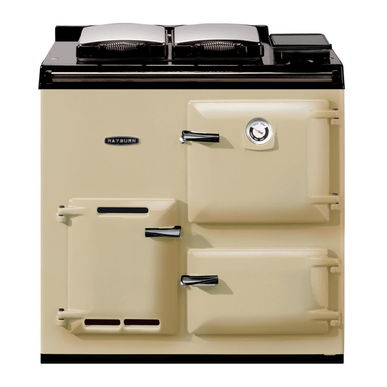
The Rayburn 200G/L Gas-Fired Cooker provides cooking
facilities only. A single atmospheric gas burner is
thermostatically controlled at cooking rates, and operates
at a low bypass rate when idling.
The exhaust flue connection of the appliance is in Open
Flue form, operating on natural draught.
Facilities included on the cooker are, a heat graduated
hotplate, main oven and lower oven. A timing programmer
is also available, as an optional extra.
Technical Specification
Natural Gas
Heat Input
5.6kW
Pressure
G20
G25
Injector Size
1.82 Bray 460
Pilot Size
38/36A
LP
Heat Input
6.3kW
Nominal Rate
G31 Propane
G30 Butane
Inlet Pressure
G31 Propane
G30 Butane
Injector Size
1.27 Bray 220
Pilot Size
4209
raywarranty@aga-web.co.uk
Installation and Servicing Instructions
for Rayburn 200G/L
Gas Fired Cooker
BE
INSTALLED
IN
20mbar
25mbar
489 g/h
497 g/h
37mbar
28mbar
below for information.
Firebricks – when handling use disposable gloves.
Fire cement – when handling use disposable gloves.
Glues and sealants – exercise caution – if these are still in liquid
form use face mask and disposable gloves.
Glass Yarn, Mineral Wool, Insulation Pads, Ceramic Fibre,
Kerosene Oil – may be harmful if inhaled, may be irritating to skin,
eyes, nose and throat. When handling avoid inhaling and contact
with skin or eyes. Use disposable gloves, face masks and eye
protection. After handling wash hands and other exposed parts.
When disposing of the product reduce dust with water spray, ensure
that parts are securely wrapped.
INSTALLATION INSTRUCTIONS
Gas connection 15mm O.D. copper.
Open flue outlet 100mm min.
Electric Supply 50Hz 3 amp fused 230V.
Weight of Appliance 275Kg.
In your own interests, and that of safety, all gas
appliances should be installed by competent persons, in
accordance with the regulations in force.
Appliance
The appliance must be installed on a solid level floor or
base of incombustible material which is capable of
supporting the total weight.
Location
The location chosen for the appliance must permit
installation and the provision of a satisfactory flue and an
adequate space for servicing and air circulation around
the appliance. See Section - Installation of Appliance -
General.
REMEMBER, when replacing a part on this appliance,
use only spare parts that you can be assured conform to
the safety and performance specification that we require.
Do not use reconditioned or copy parts that have not
clearly authorised by AGA.
1
FOR USE IN GB & IE
01/10 EINS 510974
Advertisement
Table of Contents

Subscribe to Our Youtube Channel
Related Manuals for Rayburn 200G


Summary of Contents for Rayburn 200G
- Page 1 Weight of Appliance 275Kg. SPACE. In your own interests, and that of safety, all gas The Rayburn 200G/L Gas-Fired Cooker provides cooking appliances should be installed by competent persons, in facilities only. A single atmospheric gas burner is accordance with the regulations in force.
-
Page 2: Gas Supply
Fig. 1 GAS SUPPLY FLUE SYSTEM Installation Gas pipes The following notes are intended to give general Do not use pipes of a smaller size than the appliance gas guidance:- connection. The complete installation must be tested for The cross-sectional area of the flue serving the cooker soundness and purged. - Page 3 EFFECT OF AN EXTRACTION FAN COMBUSTION AIR SUPPLY If there is any type of extract fan fitted in the same room /h of fresh air is required. as an appliance, there is a possibility that if adequate air VENTILATION inlet area from outside is not provided, spillage of the products from the appliance flue could occur when the extract fan is in operation.
- Page 4 Preliminary Installation The appliance is delivered assembled with the exception of the following items which are supplied separately packed and require assembly. 1. Draught Diverter Assembly See Fig. 4. 2. Appliance Rear Distance Bracket (For use when appliance is Bracket installed 25mm away from a rear wall of combustible material).
-
Page 5: Gas Installation
6. The handrail brackets are held on the front ends LIGHTING THE BURNER - of the cooker top-plate casting. Remove the travel See Fig. 7 nuts and replace with handrail brackets ensuring the fibre protecting washers are in position. Insert IMPORTANT: IF THE PILOT IS EXTINGUISHED FOR the handrail with fitted endcaps into the brackets, ANY REASON, ALWAYS WAIT AT LEAST 3 MINUTES... - Page 6 Fig. 7...
- Page 7 Note: The cooker is designed to be alight continuously, with the Thermostat at LOW during times of low cooking load or idling conditions, and the thermostat set to give the appropriate oven conditions when cooking - see the Rayburn Cook Book for recipes.
-
Page 8: Annual Servicing
Servicing Instructions To Clean Heat Exchanger and Flueways ANNUAL SERVICING a. Replace the main and pilot burner assembly as previously described. It is important that servicing is carried out by a b. Place a layer of paper on combustion chamber competent service engineer, and it is recommended baseplate. - Page 9 4. Spark Electrode behind the thermostat. a. Remove burner assembly as detailed in Servicing n. Now reverse the order of the above to Schedule. reassemble (h-b). b. Remove HT spark lead from spark electrode. c. Remove spark electrode. 7. Gas Valve d.
- Page 10 Fig. 8...
- Page 12 With AGA’s policy of continuous product improvement, the Company reserves the right to change specifications and make modifications to the appliance described at any time. Manufactured by Station Road Ketley Telford Shropshire TF1 5AQ England www.rayburn-web.co.uk www.agacookshop.co.uk www.agalinks.com...
Need help?
Do you have a question about the 200G and is the answer not in the manual?
Questions and answers