Advertisement
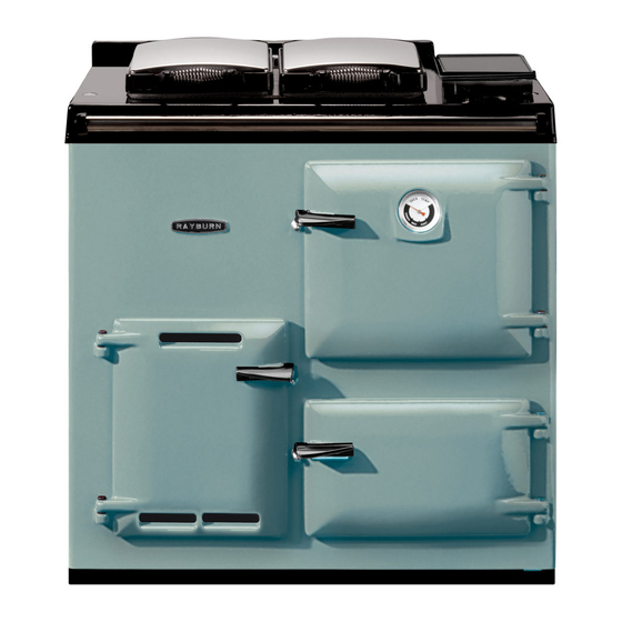
208G/L
Installation
Instructions
REMEMBER, when replacing a part on tbis appliance, use only spare parts that you can be assured conform to the safety
and performance specification that we require. Do not use reconditioned or copy parts that have not been clearly
authorised by AGA.
THIS APPLIANCE MUST BE INSTALLED IN ACCORDANCE WITH THE MANUFACTURERS INSTRUCTIONS
AND THE REGULATIONS IN FORCE AND ONLY USED IN A SUITABLY VENTILATED LOCATION.
PLEASE READ THESE INSTRUCTIONS BEFORE INSTALLING THIS APPLIANCE
For use in GB and IE
raywarranty@aga-web.co.uk
01/10 EINS 511342
Advertisement
Table of Contents

Related Manuals for Rayburn 208G


Summary of Contents for Rayburn 208G
- Page 1 208G/L Installation Instructions REMEMBER, when replacing a part on tbis appliance, use only spare parts that you can be assured conform to the safety and performance specification that we require. Do not use reconditioned or copy parts that have not been clearly authorised by AGA.
-
Page 2: Consumer Protection
Consumer Protection As manufacturers and suppliers of cooking and heating products. We take every care to ensure, as far as is reasonably practical, that these products are so designed and constructed as to meet the general safety requirement when properly used and installed. To this end, our products are thoroughly tested and examined before despatch. -
Page 3: General Specifications
PLEASE NOTE: IT IS ADVISABLE TO CHECK THE ACTUAL SIZE/WIDTH OF YOUR APPLIANCE BEFORE DIMENSIONS IN MM FINALLY FIXING ANY KITCHEN UNITS SINCE ENAMELLED CAST DESN 511371 IRON CAN VARY IN SIZE. GENERAL SPECIFICATIONS COOKER HIGH COOKER LOW HEAT INPUT kW HEAT OUTPUT WATER kW 0.36 NAT. - Page 4 INTRODUCTION REGULATIONS The Rayburn 208G/L Gas Cooker is a combined cooker In the interests of safety all gas appliances should be and domestic hot water heater. installed by competent persons in accordance with the regulations in force. It is available in Open Flue form only, operating on natural...
-
Page 5: Gas Supply
LOCATION GAS SUPPLY Installation Pipes The appliance must be installed on a solid level floor or Do not use pipes of a smaller size than the appliance gas base of incombustible material which is capable of connection. supporting the total weight. The complete installation must be tested for soundness and purged. -
Page 6: Flue System
FLUE SYSTEM AIR REQUIREMENTS SEE FIG. 1 The appliance can only be installed in a room which meets the ventilation regulations in force. But, in any The following notes are intended to give general event the room must have a permanent vent of minimum guidance. -
Page 7: Water Circulation System
WATER CIRCULATION SYSTEM The following notes are of particular importance:- Pipework should be insulated to help prevent heat loss and possible freezing, particularly where pipes are run through roof space and ventilated under floor spaces. Cisterns situated in areas which may be exposed to freezing conditions should also be insulated. -
Page 8: Preliminary Installation
PRELIMINARY INSTALLATION The appliance is delivered in a fully assembled condition with the exception of the following items which are supplied separately packed and require assembly. 1. Draught Diverter Assembly - See Fig. 3. 2. Appliance Rear Distance Bracket - (For use when appliance is installed 25mm away from a rear wall of combustible material). - Page 9 Gas Installation Connect the gas supply to the integral union gas service cock on the left hand side of the appliance. Test the whole of the gas installation, including the meter for soundness and purge in accordance with the regulations in force.
-
Page 10: Commissioning And Testing
HOW TO OPERATE COOKER COMMISSIONING AND TESTING CONTROL SEE FIG. 6 Overnight and when not required for cooking, leave cooker control knob A to L position. To increase the Water Circulating System temperature of the oven or hotplate, turn the cooker The boiler/cylinder system should be thoroughly flushed control knob A to required temperature. - Page 11 FIG. 6...
-
Page 12: Servicing Instructions
INSTRUCT USER SERVICING INSTRUCTIONS Advise the Use of the precautions necessary to prevent SEE FIG. 6 damage to the heating system and to the building in the event of the heating system remaining inoperative during NOTE: LEAVE THESE INSTRUCTIONS WITH THE frost conditions. - Page 13 5. To Replace Cooker Control Tap PRODUCTS LEAKING INTO THE ROOM. a. Turn OFF gas supply at the gas service cock D. NOTE: ONLY APPROVED RAYBURN COMBUSTION SAFETY DEVICES MUST BE FITTED TO THIS b. Remove control knob and detach cover panel (4 APPLIANCE.
- Page 16 With AGA's policy continuous product improvement, the Company reserves the right to change specifications and make modifications to the appliance described and illustrated at any time. Manufactured By Station Road Ketley Telford Shropshire TF1 5AQ England www.rayburn-web.co.uk www.agacookshop.co.uk www.agalinks.com...
Need help?
Do you have a question about the 208G and is the answer not in the manual?
Questions and answers