Advertisement
Quick Links
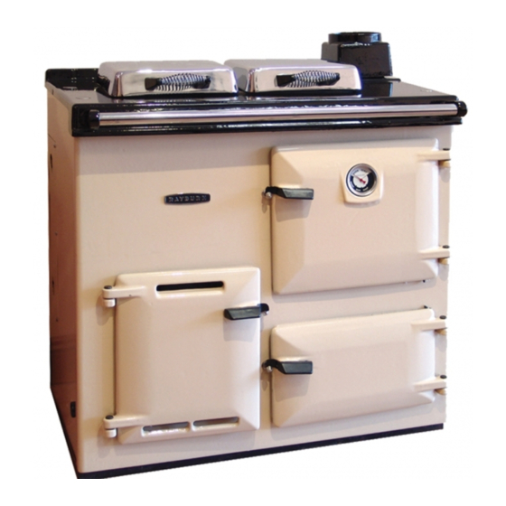
PRESSURE JET CONVERSION
For OIL FIRED COOKERS
RAYBURN
Models : OF7/G7/ 200 - 209
INSTALLATION
Servicing &
Commissioning
ISSUE No.3
DATE: 1st September 2007
:
Snughome Cookers Ltd.
Supplied by
2 Cromwell Road, Shaw, Newbury, RG14 2HL
No. - 210955
Tel.No. 01635 846787 Fax. No. 01635 846787
Advertisement

Related Manuals for Rayburn OF7


Summary of Contents for Rayburn OF7
- Page 1 PRESSURE JET CONVERSION For OIL FIRED COOKERS RAYBURN Models : OF7/G7/ 200 - 209 INSTALLATION Servicing & Commissioning ISSUE No.3 DATE: 1st September 2007 Snughome Cookers Ltd. Supplied by 2 Cromwell Road, Shaw, Newbury, RG14 2HL No. - 210955 Tel.No. 01635 846787 Fax. No. 01635 846787...
-
Page 2: General Information
Snughome in this type of conversion. GENERAL INFORMATION `This Snughome Conversion Kit for the Rayburn Cooker has been designed and manufactured by our engineers who have many year’s experience in the Conversion field and incorporates many advances in technology and design. - Page 3 Compliance with current legislation regarding Oil tanks and the siting thereof as directed by the Building Regulations Parts J & L. The fitting of Safety Fire Valves as directed by the Building Regulations and by Snughome Ltd. This Equipment must be earthed. This equipment should be wired from a double pole switched fused spur having a minimum contact gap of 3mm, rated at 5 amps This Equipment is only suitable for the appliance for which it has been designed..
-
Page 4: Tools Required
TOOLS REQUIRED - - Normal fitters tools for dismantling and assembling an Aga or Rayburn. 2. Grinder or powered Sabre saw for modifying the front casting. 3. Drills for broken off bolts, ideally 1/4 & 5/16 Whitworth... - Page 5 This guide is to help you install the Pressure Jet oil burner into an existing Rayburn 200 series cooker. It is ONLY designed to fit the models originally made for OIL or GAS opera- tion and is NOT SUITABLE for the 4 door solid fuel variety.
- Page 6 Frame cut through, ready to break off. No damage to front casting! Once the frame is cut through – careful not to saw the enamel front- unscrew the 2 bolts located under the frame. They can easily be felt under where you have been sawing. They un- screw easily with a screwdriver about 8mm across the blade.
- Page 7 Now fit the burner frame to the burner assembly The same Frame is used for both the OF7 & OF22 burners, but the positioning is different ( See photo)
- Page 8 Now fit Part 3 the 50 mm x Rope Seal around the ceramic block to seal the air. It should project up the front edges as in photo. Ensure that it is pressed tightly into position Then take part No.4 the blanket with a large hole in the centre and fit into position as in photo.
- Page 9 Fit the cast iron baffle into position with the front markings facing forward. Then place the top side insulation pad part No. 8 into position, pressing it in tightly. Now press the Top Front Insulation Pad Part No. 9 tightly into position. Press the top edges of the blankets back as far as possible so as not to restrict the air passage-ways under the hot plate.
- Page 10 Bleeding the oil pipe. There is a small bleed fitting on the pump - see photo. 50 mm to left of oil pipe connection with thumb nut. Connect 1/8* diameter bleed tube supplied and feed into a jar. Connect oil pressure test gauge by removing knurled nut (with recessed Allen key head at top of pump) .Bleed oil through from line.
- Page 11 Current legislation insists that burners are set up using Combustion Testing Equipment. In order to obtain the best performance from the burner and cooker these units must also be set up using testing equipment. As there is no ideal testing point in or on the cooker it is necessary to do this in the flue above Flue Box.
- Page 16 D A TE : 0 8 / 0 8 / 0 6 A C C E S S O R Y P A R TS L IS T A K -0 0 3 R A Y B U R N O F 7 C O N V E R S IO N . P A R T N U M B E R C O M P O N E N T D E S C R IP TIO N Q TY...
- Page 18 DIAGRAM OF OIL LINE REQUIREMENTS IF A TOP OUTLET OIL TANK IS USED. KBB 65 SENSOR FITTED ABOVE APPLIANCE BM LIFT PUMP OR SIMILAR TO ALLOW THE OIL TO GRAVITY FEED INTO THE OIL CONTROL THE HEIGHT OF THE OIL LEVEL IN THE PUMP SHOULD BE B E- TWEEN 1.5 TO 3.0 METERS ABOVE THE OIL LEVEL LINE ON THE OIL CONTROL AND SHOULD BE POSITIONED EXTERNAL TO THE BUILDING.