Advertisement
Advertisement
Table of Contents

Subscribe to Our Youtube Channel
Related Manuals for quiko QK-H300


Summary of Contents for quiko QK-H300
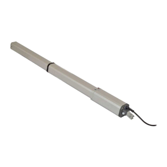
- Page 1 QK-H300 QK-H400 HYDRO HYDRAULIC SWING GATE OPENER USER INSTALLATION MANUAL...
- Page 2 QK-H300 QK-H400 TECHNICAL FEATURES QK-H300BC QK-H400BC POWER SUPPLY 230VAC 50 Hz CURRENT ABSORBED (A) POWER ABSORBED INCORPORATED CAPACITOR (mF) PROTECTION LEVEL (IP) OPENING TIME (sec) TRAVEL (mm) MAX. THRUST 9400 OPERATING TEMPERATURE - 30° + 70° Min Max (° C) THERMAL PROTECTION °...
-
Page 3: Pre-Installation Control
PRE-INSTALLATION CONTROL Before installing the automation, you must check that the gate’s shutter: The leaf turn freely in the hinges and without sticking in the ground It does not swing during its movement; is kept in axis by the special hinges; the leaves have the proper stoppages when opening and closing. -
Page 4: Installation Materials
INSTALLATION MATERIALS Fig.1 HYDRO 300 - 400 1 – Bracket to wall Length 130 mm 2 – Bolt M12 X 30 with Nut 3 – Bolt M12 x 55 with Nut 4 – Bracket, to be weld to the leaf, length 65 mm 5 - Bushing 6 –... -
Page 5: Installation
INSTALLATION Arrange the electric cables installation and connection according to the below Fig.2 Fig 2 Unloose and remove the two screws # 11 (fig 1) that fastens the tie rod cover to the cylinder. Assemble: - the wall brackets # 1 to cylinder bracket by means of the bolt and nut # 2 - the leaf bracket # 4 to cylinder rod by means of the bushing # 5 and bolt / nut # 3 3- Preassemble the cylinder to the gate according to the fig 3 and table 1... - Page 6 Fig 3 QK-H300 QK-H400 α = 90° α = 95° ° α = 90° α = 95° B (mm) B (mm) B (mm) B (mm) A (mm) A (mm) A (mm) A (mm) min max min max min max min max...
- Page 7 The opening and closing forces transmitted to the gate by the cylinder are regulated by adjusting two by pass valves. The blue valve adjusts the opening pressure. The red valve the closing pressure. Fig. 4 + increase the actuator thrust - decrease the actuator thrust 8- After installation take away the breather screw from the actuator Fig.
- Page 8 10 – To release the opening and operate the leaves manually insert the release key as shown in the Fig. 6 Fig. 6...
- Page 9 Fig 7 Risk Areas on Hinged Gates (figure 7) LEGEND OF MECHANICAL RISKS CAUSED BY MOVEMENT In accordance with the Regulation on Machinery, the following definitions are applicable: − “Danger Zones:” any area inside and/or near a machine where the presence of a person is a risk to his/her health and safety.
-
Page 10: Declaration Of Compliance
DECLARATION OF COMPLIANCE (by the installer) The undersigned: Address: in charge of the set-up, declares that the product: Gate type: Location: are in compliance with the essential safety requirements of the regulations: Regulation 89/392CE on Machinery and its subsequent amendments; EMC Regulation 89/336/CE (Legislative Decree 615/96);... - Page 11 Italia Italia hereby declares, under his liability, that the products: Actuators QK-H300, QK-H300BC, QK-H400, QK-H400BC are in compliance with the essential safety requirements of the regulations: Regulation 89/392CE on Machinery and its subsequent amendments; EMC Regulation 89/336/CE (Legislative Decree 615/96);...
- Page 12 Borinato F.lli Snc Via Seccalegno 19 36040 Sossano (Vi) Italy Tel + 39 0444 785513 Fax +39 0444 782371 INFO@QUIKO.BIZ www.quiko.biz...
Need help?
Do you have a question about the QK-H300 and is the answer not in the manual?
Questions and answers