Enerzone Everzone Solution 1.3 Installation And Operation Manual
Hide thumbs
Also See for Everzone Solution 1.3:
- Installation and operation manual (53 pages) ,
- Installation and operation manual (52 pages)
Table of Contents
Advertisement
Quick Links
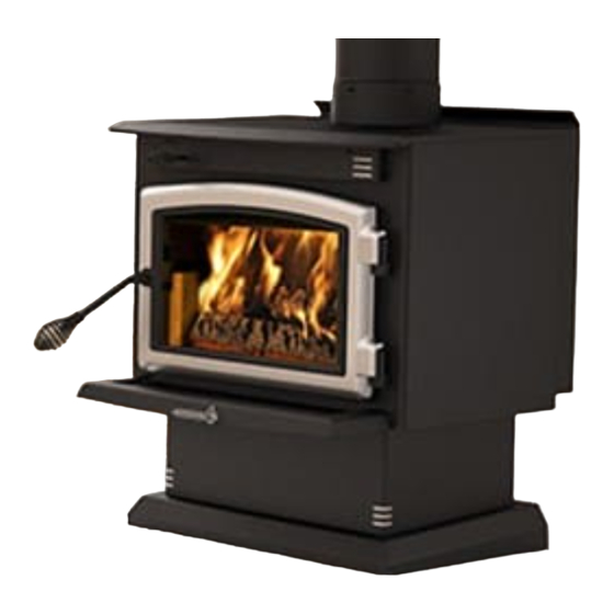
Solution 1.3
Safety tested according to ULC S627,
UL 737 and UL 1482 Standards
by Intertek Testing Services
READ AND KEEP THIS MANUAL FOR REFERENCE
This manual is available for free download on the manufacturer's web site. It is a
copyrighted document. Re-sale is strictly prohibited. The manufacturer may update this
manual from time to time and cannot be responsible for problems, injuries, or damages
arising out of the use of information contained in any manual obtained from unauthorized
sources.
Printed in Canada
INSTALLATION
AND OPERATION
MANUAL
US ENVIRONMENTAL PROTECTION
AGENCY PHASE II CERTIFIED WOOD
STOVE
www.enerzone-intl.com
Stove Builder International Inc.
250, rue de Copenhague,
St-Augustin-de-Desmoures
(Quebec) Canada G3A 2H3
Tel: (418) 878-3040
Fax: (418) 878-3001
45518A
19-04-2013
Advertisement
Table of Contents

Related Manuals for Enerzone Everzone Solution 1.3


Summary of Contents for Enerzone Everzone Solution 1.3
- Page 1 AGENCY PHASE II CERTIFIED WOOD STOVE Safety tested according to ULC S627, UL 737 and UL 1482 Standards by Intertek Testing Services www.enerzone-intl.com Stove Builder International Inc. 250, rue de Copenhague, St-Augustin-de-Desmoures (Quebec) Canada G3A 2H3 Tel: (418) 878-3040 Fax: (418) 878-3001 READ AND KEEP THIS MANUAL FOR REFERENCE This manual is available for free download on the manufacturer’s web site.
- Page 2 As one of North America’s largest and most respected wood stove and fireplace manufacturers, Stove Builder International takes pride in the quality and performance of all its products. We want to help you get maximum satisfaction as you use this product.
-
Page 3: Table Of Contents
Table of content PART A - OPERATION AND MAINTENANCE ......... 6 Safety Information ................6 1.1 Summary of Operation and Maintenance Cautions and Warnings ........6 General Information ................7 2.1 Solution 1.3 Specifications ....................7 2.2 ... - Page 4 Maintaining Your Wood Heating System ........23 5.1 Stove Maintenance ......................23 5.1.1 Cleaning Door Glass ..................... 23 5.1.2 Door adjustment ......................24 5.1.3 Replacing the Door Gasket ................... 25 5.1.4 Replacing the Glass Gasket and/or the Glass .............. 25 5.1.5 ...
- Page 5 Appendix 2: Installing the Door Overlay ..........43 Appendix 3: Installing the Optional Air Mate (AC01361) ....44 Appendix 4: Installing the Fresh Air Kit (AC01331) ......45 Appendix 5: Installing the Fire Screen (AC01318) ......46 ...
-
Page 6: Part A - Operation And Maintenance
PART A - OPERATION AND MAINTENANCE Please see Part B for installation instructions. 1 Safety Information 1.1 Summary of Operation and Maintenance Cautions and Warnings • HOT WHILE IN OPERATION, KEEP CHILDREN, CLOTHING AND FURNITURE AWAY. CONTACT MAY CAUSE SKIN BURNS. GLOVES MAY BE NEEDED FOR STOVE OPERATION. -
Page 7: General Information
General Information 2.1 Solution 1.3 Specifications Fuel Type Cordwood Test Standards (safety) ULC S627, UL 737 and UL 1482 Test Standard (emissions) EPA Method 28 (40 CFR Part 60) Heating capacity range* 250 to 1000 sq. ft. (23,2 to 92,9 m Maximum heat output** 21 800 BTU/h (6,4 kW/h) (EPA test fuel) - Page 8 Solution 1.3 Installation and Operation Manual...
- Page 9 Solution 1.3 Installation and Operation Manual...
-
Page 10: Zone Heating And How To Make It Work For You
2.2 Zone Heating and How to Make it Work for You Your new Solution 1.3 wood stove is a space heater, which means it is intended to heat the area it is installed in, as well as spaces that connect to that area, although to a lower temperature. This is called zone heating and it is an increasingly popular way to heat homes or spaces within homes. - Page 11 Lightweight firebrick is made of pumice and cement. Pumice is in fact volcanic rock, a naturally green product found in the Northwest United States. Disposal at a landfill is recommended. The door and glass gaskets are fibreglass which is spun from melted sand. Black gaskets have been dipped into a solvent-free solution.
-
Page 12: Fuel
3 Fuel 3.1 Materials That Should Not be Burned • GARBAGE OF ANY KIND, • COAL OR CHARCOAL, • TREATED, PAINTED OR COATED WOOD, • PLYWOOD OR PARTICLE BOARD, • FINE PAPER, COLORED PAPER OR CARDBOARD, • SALT WATER DRIFTWOOD •... -
Page 13: Log Length
3.2.3 Log Length Logs should be cut about 1” (25 mm) shorter than the firebox so they fit in easily. Pieces that are even slightly too long make loading the stove very difficult. The most common standard length of firewood is 16” (400 mm). The pieces should be a consistent length, with a maximum of 1”... -
Page 14: How To Dry Firewood
3.2.5 How to Dry Firewood Firewood that is not dry enough to burn is the cause of most complaints about wood inserts. Continually burning green or unseasoned wood produces more creosote and involves lack of heat and dirty glass door. See Section 5: Maintaining your wood heating system for concerns about creosote. -
Page 15: Judging Firewood Moisture Content
3.2.6 Judging Firewood Moisture Content You can find out if some firewood is dry enough to burn by using these guidelines: • cracks form at the ends of logs as they dry • as it dries in the sun, the wood turns from white or cream coloured to grey or yellow, •... -
Page 16: Operating Your Stove
4 Operating Your Stove 4.1 The use of a fire screen. This stove has been tested for use with an open door in conjunction with a fire screen (AC01318, sold separately). Make sure the fire screen is properly secured on the stove to avoid any risk of fire. -
Page 17: Conventional Fire Starting
4.3.1 Conventional Fire Starting The conventional way to build a wood fire is to bunch up 5 to 10 sheets of plain newspaper and place them in the firebox. Next, place 10 or so pieces of fine kindling on the newspaper. This kindling should be very thin;... -
Page 18: Two Parallel Logs
4.3.3 Two Parallel Logs Place two spit logs in the firebox. Place a few sheets of twisted newspaper between the logs. Now place some fine kindling across the two logs and some larger kindling across those, log cabin style. Light the newspaper. 4.3.4 Using Fire Starters Many people like to use commercial fire starters instead of newspaper. -
Page 19: Ash Removal
4.4.2 Ash Removal Ash should be removed from the firebox every two or three days of full time heating. Do not let the ash build up in the firebox because it will interfere with proper fire management. The best time to remove ash is after an overnight fire when the stove is relatively cool, but there is still some chimney draft to draw the ash dust into the stove and prevent it from coming into the room. -
Page 20: Turning Down The Air Supply
Although it is important to fire each new load hot to prepare for a clean burn, do not allow the fire to burn at full intensity for more than a few minutes. DO NOT LEAVE THE STOVE UNATTENDED WHILE A NEW LOAD IS BEING FIRED HOT. DO NOT OVERFIRE. -
Page 21: Building Different Fires For Different Needs
4.4.6 Building Different Fires for Different Needs Using the air control is not the only way to match the stove’s heat output to the heat demand. Your house will need far less heat in October than in January to be kept at a comfortable temperature. If you fill the firebox full in fall weather, you will either overheat the space or turn the stove down so much that the fire will be smoky and inefficient. - Page 22 4.4.6.4 Maximum Burn Cycle Times The burn cycle time is the period between loading wood on a coal bed and the consumption of that wood back to a coal bed of the same size. The flaming phase of the fire lasts for roughly the first half of the burn cycle and the second half is the coal bed phase during which there is little or no flame.
-
Page 23: Maintaining Your Wood Heating System
5 Maintaining Your Wood Heating System 5.1 Stove Maintenance Your new stove will give many years of reliable service if you use and maintain it correctly. Some of the internal components of the firebox, such as firebricks, baffles and air tubes, will wear over time under intense heat. -
Page 24: Door Adjustment
5.1.2 Door adjustment In order for your stove to burn at its best efficiency, the door must provide a perfect seal with the firebox. Therefore, the gasket should be inspected periodically making sure to obtain an air tight fit. Airtightness can be improved with a simple latch mechanism adjustment. To increase the pressure on the gasket, remove one washer (A). -
Page 25: Replacing The Door Gasket
5.1.3 Replacing the Door Gasket It is important to maintain the gasket in good condition. After a year or more of use, the door gasket will compress and become hard, which may allow air to leak past it. You can test the condition of the door gasket by closing and latching the door on a strip of paper. -
Page 26: Cleaning And Painting The Stove
5.1.5 Cleaning and Painting the Stove Do not attempt to clean or paint the stove when the unit is hot. Painted surfaces can be wiped down with a damp cloth. Plated surfaces may be scratched by abrasive cleaners. To maintain the finish at its original brilliance, use only a damp soft cloth to clean plated surfaces. -
Page 27: Cleaning The Chimney
5.2.3 Cleaning the Chimney Chimney cleaning can be a difficult and dangerous job. don’t have experience cleaning chimneys, you might want to hire a professional chimney sweep to clean and inspect the system for the first time. After having seen the cleaning process, you can decide if it is a job you would like to take on. -
Page 28: Part B - Installation
• MIXING OF APPLIANCE COMPONENTS FROM DIFFERENT SOURCES OR MODIFYING COMPONENTS MAY RESULT IN HAZARDOUS CONDTIONS. WHERE ANY SUCH CHANGES ARE PLANNED, STOVE BUILDER INTERNATIONAL INC. SHOULD BE CONTACTED IN ADVANCE. • ANY MODIFICATION OF THE APPLIANCE THAT HAS NOT BEEN APPROVED IN WRITING BY THE TESTING AUTHORITY VIOLATES CSA B365 (CANADA), AND ANSI NFPA 211 (USA). -
Page 29: Regulations Covering Stove Installation
6.2 Regulations Covering Stove Installation When installed and operated as described in these instructions, the Solution 1.3 wood stove is suitable for use as a freestanding heater in residential installations. The Solution 1.3 wood stove is not recommended for installation in a sleeping room. In Canada, the CSA B365 Installation Code for Solid Fuel Burning Appliances and Equipment and the CSA C22.1 Canadian National Electrical Code are to be followed in the absence of local code requirements. -
Page 30: Clearances To Combustible Material
7 Clearances to Combustible Material The clearances shown in this section have been determined by test according to procedures set out in safety standards ULC S627 (Canada), UL1482 (U.S.A.) and UL737 (U.S.A.). When the stove is installed so that its surfaces are at or beyond the minimum clearances specified, combustible surfaces will not overheat under normal and even abnormal operating conditions. - Page 31 CLEARANCES (SINGLE WALL PIPE) CANADA 15½" (394 mm) 15" (381 mm) 18" (457 mm) 18" (457 mm) 10" (254 mm)* 10" (254 mm)* 18" (457 mm) 17½" (455 mm) 26¼" (667 mm) 26¼" (667 mm) 18" (457 mm) 18" (457 mm) 48"...
- Page 32 Clearances to combustible materials and floor protection Solution 1.3 Installation and Operation Manual...
-
Page 33: Floor Protector
7.3 Floor protector If the stove is to be installed on top of a combustible floor, it must be guarded by a non combustible material as shown on figure 1.3 (see the dotted line area). FLOOR PROTECTOR* CANADA 8’’ (203 mm) – Note 1 N/A (Canada only) 8’’... -
Page 34: Reducing Wall And Ceiling Clearances Safely
7.4 Reducing Wall and Ceiling Clearances Safely It is often desirable to reduce the minimum installation clearances by placing the stove closer to walls so the installation takes up less floor space. You can safely reduce the minimum clearances permanently installing shield between the stove and combustible... -
Page 35: Table Of Clearance Reduction Percentages
7.4.2 Table of Clearance Reduction Percentages Clearances may be reduced by these percentages Type of shield Sides Top % and rear % (ceiling) Sheet metal, a minimum of 24 gauge (0.61 mm) in thickness , spaced out at least 25 mm (1 in)* non- combustible spacers... -
Page 36: The Venting System
8 The Venting System 8.1 General The venting system, made up of the chimney and the connecting pipe between the stove and the chimney, acts as the engine that drives your wood heating system. Even the best stove will not function safely and efficiently as intended if it is not connected to a suitable chimney. -
Page 37: Masonry Chimneys
8.2.2 Masonry Chimneys The stove may also be connected to a masonry chimney, provided the chimney complies with the construction rules found in the building code enforced locally. The chimney must have either a clay liner or a suitably listed stainless steel liner. If the masonry chimney square... -
Page 38: The Relationship Between The Chimney And The House
8.4 The Relationship Between the Chimney and the House Because the venting system is the engine that drives the wood heating system, it must have the right characteristics. The signs of bad system design are cold backdrafting when there is no fire in the stove, slow kindling of new fires, and smoke roll-out when the door is opened for loading. -
Page 39: Supply Of Combustion Air
There are two reasons why the chimney in the house at right will cold backdraft when it is cold outside and there is no fire burning in the stove. First, the chimney runs up the outside of the house, so the air in it is colder and denser than the warm air in the house. -
Page 40: Installing The Chimney Connector
8.6 Installing the Chimney Connector The chimney connector is the single or double wall pipe installed between the stove flue collar and the chimney breech. Single wall pipe components are available from most hardware and building supply stores. These components are not usually tested to a particular standard and certified as compliant. - Page 41 The rules below are based on those found in the CSA B365 installation code. Please carefully follow these installation instruction rules, or those enforced where you live. • Maximum overall length of straight pipe: 3 m (10 ft.) including elbows. •...
-
Page 42: Appendix 1: Installing The Legs Or Pedestal
Appendix 1: Installing the Legs or Pedestal We suggest assembling the leg kit or pedestal before positioning the stove. See the following installation instructions: PEDESTAL ASSEMBLY Fix the pedestal base using the 4 bolts and washers removed in the previous step. Unscrew the 4 bolts in order to remove the 2 steel supports. -
Page 43: Appendix 2: Installing The Door Overlay
Appendix 2: Installing the Door Overlay In order to complete the assembly of your freestanding Enerzone wood stove, you need to install the door overlay. See the following installation instructions: Position the overlay on the door frame and secure it in place from behind using the 4 screws. Note: It is not necessary to remove the glass or any other component to install the overlay. -
Page 44: Appendix 3: Installing The Optional Air Mate (Ac01361)
Appendix 3: Installing the Optional Air Mate (AC01361) Most freestanding Enerzone wood stoves can be equipped with an optional air mate. This device accumulates heat and increases the air flow. See the following installation instructions: Note: Even though it is not necessary, may want to secure the optional air mate to the rear heat deflector using 2 self-drilling screws included with the air mate through the holes provided for this purpose. -
Page 45: Appendix 4: Installing The Fresh Air Kit (Ac01331)
Appendix 4: Installing the Fresh Air Kit (AC01331) The installation instructions are provided with the Fresh Air Kit (AC01331), sold separately. Solution 1.3 Installation and Operation Manual... -
Page 46: Appendix 5: Installing The Fire Screen (Ac01318)
Appendix 5: Installing the Fire Screen (AC01318) Open the door. Hold the fire screen by the two handles and bring it close to the door opening. Lean the upper part of the fire screen against the top door opening making sure to insert the top fire screen brackets behind the primary air deflector as in (Detail A). -
Page 47: Appendix 6: Installation And Use Of Optional Air Circulation Fan And Thermodisc
Appendix 6: Installation and Use of Optional Air Circulation Fan and Thermodisc An optional fan can be installed on the back of the stove to increase the air flow through the heat exchanger and to improve the flow of warm air in the room. When used regularly, the fan can provide a small increase in efficiency, up to 2 percent. - Page 48 When using the optional fan manually, allow the stove to reach operating temperature (approximately one hour), before turning it on. The increased airflow from the fan cools the firebox and could affect the start-up combustion efficiency if the fan is turned on too early. An optional thermodisc kit is provided with the fan to enable the blower to start or stop automatically when the stove is hot or too cold.
-
Page 49: Appendix 7: Exploded Diagram And Parts List
Appendix 7: Exploded Diagram and Parts List Solution 1.3 Installation and Operation Manual... - Page 50 QTY / ITEM DESCRIPTION STOVE AC01318 FIRE SCREEN 30569 ROUND WOODEN HANDLE BLACK AC01245 GOLD PLATED CAST IRON DOOR OVERLAY AC01246 BRUSHED NICKEL CAST IRON DOOR OVERLAY AC01244 BLACK CAST IRON DOOR OVERLAY 30123 SCREW #8 - 32 X 5/8'' PAN QUADREX ZINC AC07868 1/2 "...
- Page 51 QTY / ITEM DESCRIPTION STOVE SE63323 AIR CONTROL DAMPER ULTRA-QUIET 130 CFM BLOWER WITH VARIABLE SPEED AC01000 CONTROL AC05530 THERMODISC KIT 44046 THERMODISC F110-20F 60013 POWER CORD 96" X 18-3 44085 RHEOSTAT KNOB 44087 RHEOSTAT NUT 44080 RHEOSTAT WITH NUT 44070 CROSSFLOW BLOWER 115V-60Hz-56W (B) 29011...
-
Page 52: Enerzone Limited Lifetime Warranty
ENERZONE LIMITED LIFETIME WARRANTY The warranty of the manufacturer extends only to the original consumer purchaser and is not transferable. This warranty covers brand new products only, which have not been altered, modified nor repaired since shipment from factory. Products covered under this warranty must have been manufactured after the revision date indicated below.
Need help?
Do you have a question about the Everzone Solution 1.3 and is the answer not in the manual?
Questions and answers