Respironics REMstar User Manual
M series
Hide thumbs
Also See for REMstar:
- User manual (24 pages) ,
- Instruction manual (8 pages) ,
- Quick setup manual (2 pages)
Table of Contents
Advertisement
Quick Links
Advertisement
Table of Contents

Related Manuals for Respironics REMstar


Summary of Contents for Respironics REMstar
- Page 1 REMstar M Series with SmartCard 1058374 JR 3/05/2009 EN-DOM...
- Page 2 Fill in the information below when you receive the mportant REMstar M Series system. Serial No.: _______________________________ (located on the bottom of the device) System Prescribed for: __________________________________________ Date of Purchase or Rental: ______________________________________ Pressure Setting: _____ cm H Mask Type: __________________________________________________...
-
Page 3: Table Of Contents
1.4 System Overview .......................1-4 1.4.1 Breathing Circuit Overview ................1-6 1.5 Glossary .........................1-6 1.6 Symbol Key ........................1-7 1.7 How to Contact Respironics ..................1-8 Chapter 2: Device Controls and Displays .................2-1 2.1 Controls and Displays ....................2-1 2.1.1 Control Panel Inactivity ................2-2 2.2 Rear Panel ........................2-2 Chapter 3: Setup ..........................3-1... - Page 4 Chapter 5: Alerts and Troubleshooting ..................5-1 5.1 Device Alerts ....................... 5-1 5.2 Troubleshooting ......................5-4 Chapter 6: Accessories ........................6-1 6.1 Adding a Humidifier ....................6-1 6.2 Using the SmartCard ....................6-1 6.3 Adding Supplemental Oxygen ................6-2 Chapter 7: Cleaning and Maintenance..................7-1 7.1 Cleaning the Device ....................
-
Page 5: Chapter 1: Introduction
This chapter provides information on: • System contents • Intended use • Warnings, cautions, and contraindications • System overview • Glossary and symbol key • How to contact Respironics ystEM ontEnts Your REMstar M Series system includes the following items: Carrying Case User Manual Flexible Tubing Power Supply Reusable Gray Foam Filter Disposable Ultra-fine Filter AC Power Cord Device 1–1 s igURE ystEM ontEnts... -
Page 6: Intended Use
The Respironics REMstar M Series system is a CPAP (Continuous Positive Airway Pressure) device designed for the treatment of Obstructive Sleep Apnea only in spontaneously breathing patients weighing more than 66 lbs (30 kg). The device is to be used only on the instruction of a licensed physician. Your home care provider will make the correct pressure settings according to your health care professional’s prescription. aRnings aUtions ontRaindiCations Caution: US federal law restricts this device to sale by or on the order of a physician. -
Page 7: Cautions
• Contact your health care professional if symptoms of sleep apnea recur. • If you notice any unexplained changes in the performance of this device, if it is making un- usual or harsh sounds, if the device or the power supply are dropped or mishandled, if water is spilled into the enclosure, or if the enclosure is broken, discontinue use and contact your home care provider. • Repairs and adjustments must be performed by Respironics-authorized service personnel only. Unauthorized service could cause injury, invalidate the warranty, or result in costly damage. • Periodically inspect electrical cords, cables, and the power supply for damage or signs of wear. Discontinue use and replace if damaged. • To avoid electric shock, unplug the device before cleaning it. DO NOT immerse the device in any fluids. -
Page 8: Contraindications
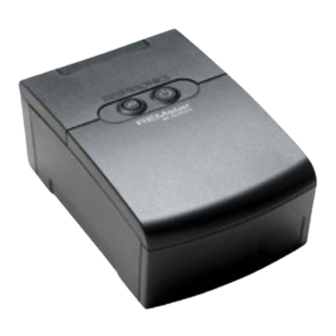
• Pneumothorax • Pneumocephalus has been reported in a patient using nasal Continuous Positive Airway Pres- sure. Caution should be used when prescribing CPAP for susceptible patients such as those with: cerebral spinal fluid (CSF) leaks, abnormalities of the cribriform plate, prior history of head trauma, and/or pneumocephalus. (Chest 1989; 96:1425-1426) The use of positive airway pressure therapy may be temporarily contraindicated if you exhibit signs of a sinus or middle ear infection. Not for use with patients whose upper airways are by- passed. Contact your physician if you have any questions concerning your therapy. ystEM vERviEW The REMstar M Series device, shown in Figure 1–2, is a sleep apnea therapy system that delivers Continuous Positive Airway Pressure (CPAP). CPAP maintains a constant level of pres- sure throughout the breathing cycle. When prescribed for you, the device provides a special feature to help make your therapy more comfortable. The ramp function allows you to lower the pressure when you are trying to fall asleep. The air pressure will gradually increase until your prescription pressure is reached. You also have the option of not using the ramp feature at all. 1–2 REM igURE staR ERiEs EviCE staR... -
Page 9: System Overview
Figure 1–3 illustrates many of the device features, described in the table below. Start/Stop Ramp Button Button Power Inlet Display Screen Air Outlet (under door) Medical Filter Area Equipment Note (on bottom) Accessory Module 1–3 s igURE ystEM vERviEW EviCE EatURE EsCRiption Accessory Module If applicable, insert optional accessory module here. Air Outlet Connect the flexible tubing here. -
Page 10: Glossary
1.4.1 b REathing iRCUit vERviEW The patient breathing circuit, shown in Figure 1–4, consists of the following: • Circuit tubing to deliver air from the device to your interface (e.g., mask) • A mask or other patient interface device to deliver the prescribed pressure to your nose or nose and mouth, depending on which interface has been prescribed for you • An exhalation device to vent exhaled air from the circuit Patient Interface (Typical) Exhalation Exhalation Mask's Device Port Connector Circuit Flexible Tubing Tubing Connector Circuit with Separate Circuit with Mask with Exhalation Device Integrated Exhalation Port 1–4 t igURE ypiCal REathing... -
Page 11: Symbol Key
CRonyM Efinition Hours of The total amount of time that the blower has been on . Patient Use Liters Per Minute Obstructive Sleep Apnea Patient Data The display mode in which the patient can view certain stored information, Mode such as session count. Patient Setup The display mode in which the patient can change patient-adjustable Mode... - Page 12 EspiRoniCs To have your device serviced, contact your home care provider. If you need to contact Respironics directly, call the Respironics Customer Service department at 1-800-345-6443 or 1-724-387-4000. You can also use the following address: Respironics 1001 Murry Ridge Lane Murrysville, Pennsylvania 15668-8550 USA staR ERiEs anUal...
-
Page 13: Controls And Displays
2: d haptER EviCE ontRols and isplays This chapter describes the device’s control buttons and displays, patient circuit connections, and rear panel connections. ontRols and isplays Figure 2–1 shows the two primary control buttons on the REMstar M Series device. 2–1 p igURE RiMaRy ontRol Uttons These buttons are described below. Utton EsCRiption Ramp – When the airflow is on, this button allows you to activate or restart the ramp function. -
Page 14: Control Panel Inactivity
2–3 d igURE EviCE ontRol anEl 2.1.1 C ontRol anEl naCtivity Some screens have time-out periods. The screen’s timer starts when the screen is initially displayed and is restarted whenever a button is pressed. The screen times out after one minute if there is no activity and returns to the Standby screen. anEl Figure 2–4 shows the REMstar M Series device’s rear panel (without a humidifier). 2–4 R igURE anEl The rear panel contains the following: • An accessory slot for optional accessories such as the SmartCard or modem (see Chapter 6, Accessories, for more information). • A filter area where each filter supplied with your device should be inserted. • A DC power inlet where the power cord is connected (see Chapter 3, Setup, for complete information on supplying power to the device). -
Page 15: Chapter 3: Setup
3: s haptER EtUp This chapter provides instructions on how to: • Install the air filters • Position the device • Connect the breathing circuit • Supply power to the device nstalling thE iltERs Caution: A properly installed, undamaged foam filter is required for proper operation. The device uses a gray foam filter that is washable and reusable, and an optional white ultra-fine filter that is disposable. The reusable filter screens out normal household dust and pollens, while the optional ultra-fine filter provides more complete filtration of very fine particles. The gray reus- able filter must be in place at all times when the device is operating. The ultra-fine filter is recom- mended for people who are sensitive to tobacco smoke or other small particles. Two reusable gray foam filters and one disposable ultra-fine filter are supplied with the device. If your filters are not already installed when you receive your device, you must at least install the reusable gray foam filter before using the device. To install a filter: 1. If you are using the optional disposable white ultra-fine filter, insert it into the filter area first, mesh-side facing in, towards the device. 2. Insert the gray foam filter into the filter area as shown in Figure 3–1. - Page 16 Air must flow freely around the device for the system to work properly. Make sure the device is away from any heating or cooling equipment (e.g., forced air vents, radiators, air conditioners). onnECting thE REathing iRCUit To use the system, you will need the following accessories in order to assemble the recommended circuit: • Respironics interface (e.g, nasal mask) with integrated exhalation port (or Respironics inter- face with a separate exhalation device such as the Whisper Swivel® II) • Respironics 6 ft. (1.83 m) flexible tubing • Respironics headgear (for the patient interface) Warning: If the device is used by multiple persons (e.g., rental devices), a low- resistance, main flow bacteria filter should be installed in-line between the device and the circuit tubing to prevent contamination.
- Page 17 2. Connect the tubing to the mask: a. If you are using a mask with a built-in exhalation port, connect the mask’s connector to the flexible tubing, as shown in Figure 3–3. Exhalation Port Mask's Connector Flexible Tubing Connector 3–3 C igURE onnECting a asK With Uilt xhalation b. If you are using a mask with a separate exhalation device, connect the open end of the flexible tubing to the exhalation device as shown in Figure 3–4. Position the exhalation device so that the vented air is blowing away from your face. Connect the mask’s connec- tor to the exhalation device. Exhalation Device Flexible Tubing Connector 3–4 C igURE onnECting a asK With a EpaRatE xhalation...
-
Page 18: Using Ac Power
Upplying oWER to thE EviCE You can power the device using AC or DC power. Caution: If this device has been exposed to either very hot or very cold tempera- tures, allow it to adjust to room temperature before beginning the following setup procedures. Warning: Route the wires to avoid tripping. Warning: This device is activated when the power cord is connected. -
Page 19: Using Dc Power
Damage to the vehicle or the device may occur. Caution: Only use a Respironics DC Power Cord and Battery Adapter Cable. Use of any other system may cause damage to the device or vehicle. - Page 20 oMplEtE ssEMbly xaMplE Figure 3–7 shows an example of how a complete assembly will look, with breathing circuit con- nected and power applied to the device. 3–7 f igURE inal ssEMbly xaMplE Figure 3–8 shows an example of how you should route your tubing and situate your device on your night stand for the best setup possible. This will help prevent the device from falling off your night stand or table. 3–8 R igURE ECoMMEndEd EviCE and Ubing laCEMEnt staR ERiEs anUal...
-
Page 21: Fosq Questionnaire
4: d haptER EviCE pERation This chapter explains how to start the device and change the settings. taRting thE EviCE 1. Plug the device in to an AC or DC power source. The three primary buttons light up and the Software Version screen momentarily appears, shown in Figure 4–1. V 1.0 4–1 s igURE oftWaRE ERsion CREEn Note: Version 1.0 shown in Figure 4–1 is an example. Your device may have a different software version installed. 2. The next screen to appear is the Standby screen, shown in Figure 4–2. You can access the FOSQ questionnaire or patient settings and data from this screen. See Section 4.3 for instructions on how to navigate the display screens. - Page 22 Symbols also appear on the Active Display screen or Standby screen to indicate when certain conditions are turned on or detected. These symbols are described below: yMbol EsCRiption Ramp – You can initiate the ramp feature by pressing the Ramp button. The ramp symbol displays on the Active Display screen when the ramp function is active. Mask Mask Leak Alert – This flashing text displays on the Active Display screen Leak if the Mask Alert setting is enabled and the device detects an excessive mask leak.
- Page 23 hanging thE EviCE Ettings You can view the set pressure on the Active Display screen, and the following information on the Patient Data screens: • Therapy usage hours • Number of sessions greater than 4 hours • Compliance check value • Summary Data • Compliance VIC Additionally, you can view and modify the following settings on the Patient Setup screens: • Altitude • Ramp starting pressure (if enabled by your home care provider) • Mask alert (enable/disable) • Auto off (enable/disable) 4.3.1 n avigating thE isplay CREEns Use the button to navigate to the next screen and the button to navigate to the previous screen.
- Page 24 The Patient Data screens are described below. Standby Screen The Standby screen appears when you first apply power to the device. You can access the Patient Data menu from this screen by – FOSQ Setup pressing the buttons. Note: You can also access the Patient Setup screens by pressing the + button, and the FOSQ questionnaire by pressing the —...
- Page 25 Compliance VIC (Visual Inspection Check) Screen This screen displays the 30-day compliance start date, the number of days for which at least 4 hours of therapy was recorded, and a number used by your home care provider to validate that the data provided by you is the data taken from the Compliance VIC screen.
- Page 26 Altitude Setting Screen Altitude This screen allows you to modify the altitude adjustment setting. Press the + or – buttons to increase or decrease the setting by 1 2 3 increments of 1: • 1 = less than 2500 ft. (<762 m) • 2 = 2500 to 5000 ft. (762 m to 1524 m) • 3 = 5001 to 7500 ft. (1525 m to 2286 m) Note: Elevations over 7500 ft.
- Page 27 fosQ Q oMplEting thE UEstionnaiRE Note: The FOSQ option only appears on the Standby screen if a SmartCard is inserted or a modem is connected to the device. From the Standby screen, you can access the FOSQ questionnaire by pressing the – button. The FOSQ test is a ‘quality of life’ questionnaire designed specifically for people with sleep disorders. The results allow health care professionals to see how therapy has improved the quality of your life. By completing the questionnaire periodically, you can provide valuable information about the effectiveness of your treatment. The device can record your answers on the SmartCard or via a wired or wireless modem for later review by the health care professional. Contact your home care provider for further instructions. Note: If your health care professional or home care provider instructs you to complete the questionnaire, he or she will provide you with the questions, and you can enter your answers into the device.
-
Page 28: Patient Reminder Screen
atiEnt EMindER CREEn Your home care provider may set a patient reminder that will appear periodically to alert you to take certain actions, such as replacing your mask. A message will appear whenever the device transitions from the Active Display to the Standby state if the period of time specified by your provider has expired. You can acknowledge the message by pressing any of the display buttons (+, –, or ). If you do not acknowledge the message within six minutes of it appearing on the screen, it will time out and disappear. The message will continue to display for three consecutive days whenever the device transitions from Active to Standby until it is acknowledged. If, after three days, you still have not acknowledged the message, then the reminder period will reset and no more reminders will display until the next time the patient reminder setting expires. Figure 4–7 shows an example of a patient reminder message. Patient Reminder Check your mask, a new one may be available. Call your provider. 4–7 p igURE atiEnt EMindER CREEn staR ERiEs anUal... -
Page 29: Chapter 5: Alerts And Troubleshooting
5: a haptER lERts and RoUblEshooting This chapter describes the device alerts and also provides troubleshooting information for issues you may run into when using the device. EviCE lERts The device provides two alert levels, high and medium priority. • High Priority – These alerts require immediate operator response. The alert signal consists of a high priority sound, which is a continuous two-beep pattern (indicated in the following table as: • • • •). Additionally, the backlights on the buttons will provide a high priority flashing pattern consisting of a continuous, bright-to-off, two-flash pattern (indicated in the following table as: ◊◊ ◊◊ ◊◊). • Medium Priority – These alerts require prompt operator response. The alert signal consists of a medium priority sound, which is a continuous one-beep pattern (indicated in the following table as: • •). Additionally, the backlights on the buttons will provide a medium priority flashing pattern consisting of a continuous, bright-to-dim, one-flash pattern (indicated in the following table as: ◊ ◊... - Page 30 lERt UMMaRy ablE The following table summarizes the high and medium priority alerts. lERt UdiblE isUal EviCE Ction ossiblE aUsE atiEnt Ction ndiCatoR ndiCatoR System Error • • • • Backlights: The device enters the Device failure Press any of the display ◊◊ ◊◊ ◊◊ “Safe state” in which screen buttons to silence the device power the alert.
- Page 31 lERt UdiblE isUal EviCE Ction ossiblE aUsE atiEnt Ction ndiCatoR ndiCatoR Mask Leak • • The device continues The breathing Check your breathing Backlights: to operate. circuit is discon- circuit connections and re- ◊ ◊ ◊ nected or there is connect the tubing if it has a large air leak.
- Page 32 RoUblEshooting The table below lists some of the problems you may experience with your device or mask and pos- sible solutions to those problems. RoblEM appEnEd hat to Nothing happens There’s no power If you are using AC power, check the outlet when you apply power at the outlet or the power and verify that the device is properly to the device.
- Page 33 RoblEM appEnEd hat to The device’s display is The device or power Unplug the device and the power supply. erratic. supply has been Reapply power to the device. If the problem dropped or mishan- continues, relocate the device to an area with dled, or the device lower EMI emissions (e.g., away from electronic or power supply is...
- Page 34 RoblEM appEnEd hat to The device has fallen The device may not Always make sure your device is placed on off your table or night have been properly a hard, flat surface so the rubber feet on the stand. seated on the night bottom of the device can adhere to the surface stand, or the place- (make sure there is no fabric under the device).
- Page 35 RoblEM appEnEd hat to You are having prob- You have lost the If you are not using a humidifier, you cannot lems connecting the air outlet port or are connect your tubing to the device without the tubing to the device. traveling and forgot detachable air outlet port, shown below.
- Page 36 Increase the room humidity. Consult with nose dryness. your health care professional about using a Respironics humidifier with the device. If you have a humidifier, refer to the instructions included with your humidifier to make sure it is working properly.
-
Page 37: Chapter 6: Accessories
For safe operation, the humidifier must always be positioned below the breathing circuit connection at the mask. The humidifier must be level for proper operation. Refer to your humidifier’s instructions for complete setup information. sing thE MaRt Some REMstar M Series systems come with a SmartCard accessory module installed in the accessory slot on the back of the device to record information for the home care provider. Your home care provider may ask you to periodically remove the SmartCard and send it to him/her for evaluation. Note: The SmartCard does not need to be installed for the device to work properly. -
Page 38: Adding Supplemental Oxygen
UpplEMEntal xygEn Oxygen may be added at the mask connection. Please note the warnings listed below when using oxygen with the device. aRnings • When using oxygen with this system, the oxygen supply must comply with local regulations for medical oxygen. • When using oxygen with this system, a Respironics Pressure Valve must be placed in-line with the patient circuit. Failure to use the pressure valve could result in a fire hazard. • Oxygen accelerates fires. Keep the device and the oxygen container away from heat, open flames, any oily substance, or other sources of ignition. Do not smoke in the area near the device or the oxygen. • When using oxygen with this system, turn the device on before turning on the oxygen. Turn the oxygen off before turning the device off. This will prevent oxygen accumulation in the device. • If administering fixed-flow supplemental oxygen, the oxygen concentration may not be con- stant. The inspired oxygen concentration will vary, depending on the CPAP setting, patient breathing pattern, and leak rate. Substantial leaks around the mask may reduce the inspired oxygen concentration to less than the expected concentrations. -
Page 39: Chapter 7: Cleaning And Maintenance
7: C haptER lEaning and aintEnanCE This chapter describes how to clean the device and its filters and provides tips on traveling with your REMstar M Series system. lEaning thE EviCE Warning: To avoid electrical shock, always unplug the power cord from the wall outlet or DC power source before cleaning the device. Caution: Do not immerse the device in liquid or allow any liquid to enter the enclosure, inlet filter, or any opening. - Page 40 7–1 R igURE EMoving thE iltERs 3. Examine each filter for cleanliness and integrity. 4. Wash the gray foam filter in warm water with a mild detergent. Rinse thoroughly to remove all detergent residue. Allow the filter to air dry completely before reinstalling it. If the foam filter is torn, replace it. (Only Respironics-supplied filters should be used as replacement filters.) 5. If the optional white ultra-fine filter is dirty or torn, replace it. 6. Reinstall the filters, inserting the white ultra-fine filter first if applicable, as shown in Figure 7–2. 7–2 R igURE Einstalling thE iltERs Caution: Never install a wet filter into the device. It is recommended that you clean the filter in the morning and alternate using the two foam filters provided with the system to ensure sufficient drying time for the cleaned filter.
-
Page 41: Cleaning The Tubing
Clean the tubing daily. Disconnect the flexible tubing from the device. Gently wash the tubing in a solution of warm water and a mild detergent. Rinse thoroughly. Air dry. ERviCE The REMstar M Series device does not require routine servicing. Warning: If you notice unexplained changes in the performance of this device, if it is making unusual or harsh sounds, if the device or power supply... - Page 42 When traveling, the carrying case is for carry-on luggage only. The carrying case will not protect the system if it is put through checked baggage. For your convenience at security stations, there is a note on the bottom of the device stating that it is medical equipment. It may be helpful to bring this manual along with you to help security personnel understand the REMstar M Series device. If you typically use a humidifier with your device, but leave the humidifier home when traveling, make sure you attach the air outlet port to your device when you remove the humidifier from the device. You need the port to connect the tubing directly to your device. Figure 7–3 illustrates how to attach the air outlet port. Attach Air Outlet Port to the Device 7–3 a...
-
Page 43: Chapter 8: Specifications
8: s haptER pECifiCations nviRonMEntal pERating toRagE 41° F to 95° F -4° F to 140° F EMpERatURE (5° C to 35° C) (-20° C to 60° C) 15 to 95% (non-condensing) 15 to 95% (non-condensing) ElativE UMidity 77 to 101 kPa (0 - 7500 ft.) tMosphERiC REssURE hysiCal... -
Page 44: Pressure
REssURE 4.0 to 20.0 cm H O (in 0.5 cm H O increments) Pressure Increments: Pressure Stability: 4.0 to 20.0 cm H O (±1.0 cm H Measured in accordance with EN ISO 17510-1 @ 1/3, 2/3, and Pmax with BPM set to 10, 15, and 20 BPM @ 68° F (±9° F) (20° C ±5° C), 50% RH (±5%). Maximum Flow: 35 LPM Measured in accordance with EN ISO 17510-1 @ 1/3, 2/3, and Pmax with BPM set to 10, 15, and 20 BPM @ 73° F (±3.6° F) (23° C ±2° C), 50% RH (±5%). isposal Dispose of the device in accordance with local regulations. staR ERiEs anUal... - Page 45 a: EMC i ppEndix nfoRMation ’ This device is intended for use in the UidanCE and anUfaCtURER EClaRation lECtRoMagnEtiC Missions electromagnetic environment specified below. The user of this device should make sure it is used in such an environment. Missions oMplianCE lECtRoMagnEtiC nviRonMEnt UidanCE RF emissions Group 1 The device uses RF energy only for its internal function. Therefore, its CISPR 11 RF emissions are very low and are not likely to cause any interference in nearby electronic equipment.
- Page 46 ’ This device is intended for use in the UidanCE and anUfaCtURER EClaRation lECtRoMagnEtiC MMUnity electromagnetic environment specified below. The user of this device should make sure it is used in such an environment. iEC 60601 t MMUnity EvEl oMplianCE EvEl lECtRoMagnEtiC nviRonMEnt UidanCE Portable and mobile RF communications equipment should be used no closer to any part of the device, including cables, than the recommended separation distance calculated from the equation applicable to the frequency of the transmitter.
- Page 47 Respironics, Inc. warrants that the system shall be free from defects of workmanship and materials and will perform in accordance with the product specifications for a period of two (2) years from the date of sale by Respironics, Inc. to the dealer. If the product fails to perform in accordance with the product specifications, Respironics, Inc. will repair or replace – at its option – the defective material or part. Respironics, Inc. will pay customary freight charges from Respironics, Inc. to the dealer location only. This warranty does not cover damage caused by accident, misuse, abuse, alteration, and other defects not related to material or workmanship. Respironics, Inc. disclaims all liability for economic loss, loss of profits, overhead, or consequential damages which may be claimed to arise from any sale or use of this product. Some states do not allow the exclusion or limitation of incidental or consequential damages, so the above limitation or exclusion may not apply to you. This warranty is given in lieu of all other express warranties. In addition, any implied warranties – including any warranty of merchantability or fitness for the particular purpose – are limited to two years. Some states do not allow limitations on how long an implied warranty lasts, so the...
Need help?
Do you have a question about the REMstar and is the answer not in the manual?
Questions and answers