Table of Contents
Advertisement
Quick Links
Advertisement
Table of Contents
Troubleshooting

Related Manuals for ESAB ESP-101


Summary of Contents for ESAB ESP-101
- Page 1 ESP-101 Plasma Arc Cutting System Instruction Manual This manual provides installation and operation instructions for the following ESP-101 cutting packages starting with Serial No.: PxxJ943xxx Consoles: P/N 0558004880 - ESP-101 460V P/N 0558005215 - ESP-101 380-400V CE 0558005965 03/2013...
-
Page 2: User Responsibility
BE SurE ThIS INforMaTIoN rEaChES ThE oPEraTor. You CaN gET ExTra CoPIES Through Your SuPPlIEr. CauTIoN These INSTruCTIoNS are for experienced operators. If you are not fully familiar with the principles of operation and safe practices for arc welding and cutting equipment, we urge you to read our booklet, “Precautions and Safe Practices for arc Welding, Cutting, and gouging,”... -
Page 3: Table Of Contents
2.3 ESP-101 Plasma Arc Cutting System: ........ - Page 4 TaBlE of CoNTENTS 6.0 Troubleshooting .........................47 6.1 Troubleshooting ................. .47 6.2 List of Help Codes .
-
Page 5: Safety Precautions
SECTIoN 1 SafETY PrECauTIoNS 1.0 Safety Precautions 1.1 Safety - English WarNINg: These Safety Precautions are fIrES aND ExPloSIoNS -- heat from for your protection. They summarize flames and arcs can start fires. hot precautionary information from the slag or sparks can also cause fires and references listed in additional Safety explosions. - Page 6 SECTIoN 1 SafETY PrECauTIoNS 1. Be sure the power source frame (chassis) is con- 3. Welders should use the following procedures to nected to the ground system of the input power. minimize exposure to EMF: 2. Connect the work piece to a good electrical A.
- Page 7 SECTIoN 1 SafETY PrECauTIoNS 5. WarNINg: This product, when used for welding 1. Always have qualified personnel perform the instal- or cutting, produces fumes or gases lation, troubleshooting, and maintenance work. which contain chemicals known to Do not perform any electrical work unless you are the State of California to cause birth qualified to perform such work.
- Page 8 SECTIoN 1 SafETY PrECauTIoNS MEaNINg of SYMBolS - as used 5. AWS C5.5 - "Recommended Practices for Gas Tung- throughout this manual: Means atten- sten Arc Welding“ tion! Be alert! Your safety is involved. 6. AWS C5.6 - "Recommended Practices for Gas Metal Means immediate hazards which, Arc Welding"“...
-
Page 9: Safety - Spanish
SECTIoN 1 SEgurIDaD 1.2 Safety - Spanish la escoria puede estar caliente y desprenderse con velocidad. Personas cercanas deberán usar aDVErTENCIa: Estas Precauciones de gafas de seguridad y careta protectora. Seguridad son para su protección. Ellas hacen resumen de información prove- fuEgo Y ExPloSIoNES -- El calor de niente de las referencias listadas en la sección las flamas y el arco pueden ocacionar... - Page 10 SECCIoN 1 SEgurIDaD 1. Asegúrese de que el chasis de la fuente de poder 3. Los soldadores deberán usar los siguientes proced- esté conectado a tierra através del sistema de imientos para minimizar exponerse al EMF: electricidad primario. 2. Conecte la pieza de trabajo a un buen sistema de A.
- Page 11 SECCIoN 1 SEgurIDaD 5. aDVErTENCIa-- Este producto cuando se uti- 1. Siempre tenga personal cualificado para efec- liza para soldaduras o cortes, tuar l a instalación, diagnóstico, y mantenimiento produce humos o gases, los del equipo. No ejecute ningún trabajo eléctrico a cuales contienen químicos menos que usted esté...
- Page 12 SECTIoN 1 SEgurIDaD SIgNIfICaDo DE loS SIMBoloS Significa el riesgo de un peligro -- Según usted avanza en la lectura potencial que puede resultar en de este folleto: los Símbolos Sig- serio daño personal o la muerte. nifican ¡atención! ¡Esté alerta! Se trata de su seguridad.
-
Page 13: Safety - French
SECTIoN 1 SÉCurITÉ INCENDIES ET ExPloSIoNS -- la 1.3 Safety - french chaleur provenant des flammes ou de aVErTISSEMENT : Ces règles de sécurité l'arc peut provoquer un incendie. le ont pour but d'assurer votre protection. laitier incandescent ou les étincelles Ils récapitulent les informations de pré- peuvent également provoquer un caution provenant des références dans... - Page 14 SECTIoN 1 SÉCurITÉ 1. Assurez-vous que le châssis de la source 3. Les soudeurs doivent suivre les procédures suivantes d'alimentation est branché au système de mise à pour minimiser l'exposition aux champs électriques la terre de l'alimentation d'entrée. et magnétiques : 2.
- Page 15 SECTIoN 1 SÉCurITÉ 5. aVErTISSEMENT : Ce produit, lorsqu'il est utilisé ENTrETIEN DE l'ÉQuIPEMENT -- un équipe- dans une opération de soudage ou de ment entretenu de façon défectueuse ou coupage, dégage des vapeurs ou des inadéquate peut causer des blessures gaz contenant des chimiques consid- graves ou mortelles.
- Page 16 SECTIoN 1 SÉCurITÉ SIgNIfICaTIoN DES SYMBolES aVErTISSEMENT Ce symbole, utilisé partout dans ce manuel, Signifie un danger potentiel qui peut entraîner des signifie "attention" ! Soyez vigilant ! Votre blessures graves ou mortelles. sécurité est en jeu. aTTENTIoN DaNgEr Signifie un danger qui peut entraîner des blessures Signifie un danger immédiat.
-
Page 17: Description
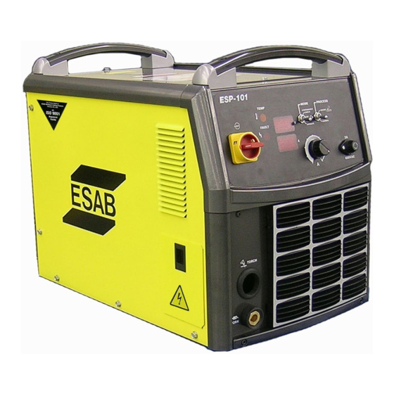
2.0 Description 2.1 general As shipped, the ESP-101 is fully assembled and ready to cut after being connected to input power, a source of compressed air, and a PT-37 torch. The ESP-101 system uses the heavy-duty PT-37 (Mechanized Plasma) torch to deliver cutting power for cutting materials up to 1-1/4 inch (32 mm) thick. -
Page 18: Esp-101 Plasma Arc Cutting System
DESCrIPTIoN 2.3 ESP-101 Plasma arc Cutting System: The ESP-101 plasma cutting system combines the newly redesigned ESP-101 console and PT-37 torch. The PT-37 plasma cutting torch is designed to provide increased performance and longer consumable life resulting in higher production rates at lower costs. -
Page 19: Package Ordering Information
DESCrIPTIoN 2.4 Package ordering Information: Mechanized Package ordering Information: The components that are included in the ESP-101 mechanized packages may be purchased separately by using the ap- propriate P/N when placing orders. Individual part numbers are listed below: available Packages: ESP-101: 460 V CNC PT-37 with rack 25 ft (7.6 m) ............................... -
Page 20: System And Optional Accessories
DESCrIPTIoN 2.6 System and optional accessories Tua2 auto-Transformer ..................0459145880 Converts an input voltage of 208, 230, 400, 475, 500, or 575 V to 460 V for use with an ESP-101 460 V console. remote Junction Box ....................0558004887 The Remote Junction Box provides a means to extend the total length of the PT-37 Torch. When used in combination with 50 ft., 75 ft., or 100 ft. -
Page 21: Installation
Lifting instruc 3.3 Placement and location After selecting an installation site, place the ESP-101 in the desired location. The unit may be lifted by either an With power source overhead crane or forklift truck. If using forklift truck, be sure that the lift forks are long enough to extend com- pletely under the base. -
Page 22: Primary Input Connections
CorD To ThE uNIT WhEN CoNNECTIoNS arE MaDE INSIDE of ThE PoWEr SourCE. 3.5 Primary Input Connections STaNDarD uNITS CE uNITS (NoN-CE) (EuroPE) The ESP-101 460V consoles are equipped PHASE PHASE with approximately 15 ft. of 4-conductor Black Brown input power cable for 3 phase connection. -
Page 23: Section 3 Installation
In an event where the power cord is pulled from the machine, the ground lead must not break from the ground connection before the power leads have broken from their connection. Refer to Table 3-1 for recommended input conductors and line fuse sizes. ESP-101 ESP-101 (With optional auto-transformer) Input requirements Input &... -
Page 24: Tua2 Auto-Transformer Primary Input Connections
Connecting a Multi-Voltage Version The ESP-101 460V version is equipped with an input power cable which may be used to connect to the output of the TUA2 Auto-Transformer. You may either use the factory-installed input power cable (4/c, type SO (90 °C) or provide your own in- put power leads. - Page 25 L2, L3 leads to the voltage terminals that match your input power supply voltage. Connect the ground lead to the rear ground stud. Ensure all connections are secure. Do not overtighten the strain relief. To ESP-101 460 V console To Fused Line...
-
Page 26: Input Air Connection
SECTIoN 3 INSTallaTIoN 3.5.2 Input air Connection Connect your air supply to the inlet connection of the filter/regulator. Pre-filtered DRY AIR SUPPLY (Customer Supplied) (90 - 150 psi / 6.2 - 10.3 bars) Replace fuse with Slo-Blo, 2 Amp, 600 V only WarNINg MaKE SurE ThE PoWEr SourCE IS SWITChED off BEforE rEMoVINg fuSE. -
Page 27: Cnc Interface Connection
INPuT (J6-1) rED +(12-30) VDC faulT SuPPlY Note: If replacing the ESP-100 with an ESP-101, reversing wires 1 and 2 on the CNC cable may be necessary for proper polarity. figure 3-5. Mechanical Cutting Interface Diagram CNC Interface Connection... -
Page 28: Cnc Interface Connection (Continued)
SECTIoN 3 INSTallaTIoN 3.6 CNC Interface Connection (continued) Start signal (pin M) Use a relay to connect this pin to “Common” (pin N) to start the cutting process. If a transistor is used for this signal, then the positive potential must be connected to pin M and the common/negative to pin N. -
Page 29: Voltage Divider Adjustment
3.7 Voltage Divider adjustment It may be necessary to adjust the Voltage Divider or VDR to match the particular height control system. There are two de- fault settings for the ESP-101 models as shipped from the factory: • STANDARD UNITS (Non-CE): 750 ohms (21:1) •... -
Page 30: Secondary Output Connections For Mechanized Cutting
CNC Control Cable (back connection) PT-37 SAFETY GROUND figure 3-6. ESP-101 Interconnection Diagram BEforE MaKINg aNY CoNNECTIoNS To ThE PoWEr SourCE ouT- WarNINg PuT TErMINalS, MaKE SurE ThaT all PrIMarY INPuT PoWEr To ThE PoWEr SourCE IS DE ENErgIZED (off) aT ThE MaIN DISCoN- NECT SWITCh. -
Page 31: Torch Installation
SECTIoN 3 INSTallaTIoN 3.9 PT-37 Torch Installation 1. Open lead access door on the left side of the ESP-101. Torch Lead Access Door 2. Route the torch cable through the access opening on the front of the console. 3. Connect the torch cable receptacle to the panel receptacle. -
Page 32: Remote Junction Box Installation
150 feet. Installation of a Remote Junction Box requires minor modifications to the ESP-101 power supply, mounting of the box itself, and connection of the extension cable. Use the diagram and steps below for installation. - Page 33 Description of esp-101 modification: The wiring modification (interconnect plug reversal) redirects the control signal from the ESP-101 internal solenoid, to the pins within the torch connection panel receptacle. The control signal is then diverted to the solenoid within the Remote Junction Box.
- Page 34 (d) Couple the free ends of the gas tubes together Important Note: Earlier versions of the ESP-101 (prior to revision G) were equipped with a pilot arc resistor. Ensure tubing is securely fastened at least 1 inch away from pilot arc resistor.
- Page 35 3. Insert the free end of the PT-37 Torch through the grommet on the other end of the RJB and make the power and gas connections as shown. Note: Extension Cable connections from the ESP-101 must be connected on the solenoid wiring side of the To PT-37 Torch Remote junction Box.
- Page 36 INSTallaTIoN C. Connecting to the ESP-101 The Extension Cable is connected to the ESP-101 in the same manner as the PT-37 Torch. 1. Open extension cable lead access door on the left side of the ESP-101. 2. Insert the extension cable and air hose through the extension cable access opening on the front of the console.
-
Page 37: Operation
CaN BurN EYES aND SKIN; NoISE CaN DaMagE hEarINg. WarNINg • Wear welding helmet with No. 6 or 7 lens shade. • Wear eye, ear, and body protection. Position the ESP-101 at least 10 feet (3 meters) from the cutting area. CauTIoN Sparks and hot slag from the cutting operation can damage the unit. 4.0 operation 4.1 ESP-101 Controls... -
Page 38: Section 4 Operation
Requires a new start signal.) 2. Gouge. Optimizes power source for gouging operations. Gouging requires higher arc voltages. In this mode the power source allows higher operating arc voltage limiting the output current to 85 amps. figure 4-2a. ESP-101 Controls... - Page 39 If after the initial sequence the display does not show the Current Setting but reverts back to displaying the model "ESP-101", the machine has detected a premature torch trigger condition. Disengage the torch trigger and restart the machine. (As a safety precaution, the ESP-101 will not power up with the torch trigger engaged.) g.
-
Page 40: Cutting With The Esp-101
WarNINg ENErgIZED WITh hIgh VolTagE If ThE TorCh SWITCh IS aCCIDEN- TallY CloSED WhEN ThE ShIElD IS rEMoVED. alWaYS rEPlaCE TorCh WITh ThE ProPEr TorCh MaNufaCTurED BY ESaB SINCE IT aloNE CoNTaINS ESaB'S SafETY INTErloCK. 4.2 Cutting with the ESP-101 A. -
Page 41: Standoff And Cut Quality
SECTIoN 4 oPEraTIoN 4.4 Standoff and Cut Quality Standoff (Arc Voltage) has a direct influence on cut quality and squareness. It is recommended that prior to cutting, that all cutting parameters are set to the manufacturer’s suggested conditions. Refer to the Operation section Process Data in the torch manual for recommendations. -
Page 42: Dross Formation
SECTIoN 4 oPEraTIoN 4.5 Dross formation Cutting speed, gas selection and variations in metal composition contribute to dross formation. The correct cut- ting standoff also has an influence on dross formation. If the arc voltage is set too high, the cut angle becomes positive. -
Page 43: Common Cutting Issues
Listed below are common cutting problems followed by the probable cause of each. If problems are determined to be caused by the ESP-101, refer to the maintenance and troubleshooting sections of this manual. If the problem is not corrected after referring to the maintenance and troubleshooting sections, contact your ESAB distributor. - Page 44 SECTIoN 4 oPEraTIoN...
-
Page 45: Maintenance
Do not permit untrained persons to inspect, clean, or repair this equipment. Use only recommended replacement parts. 5.2 Inspection and Cleaning Frequent inspection and cleaning of the ESP-101 is recommended for safety and proper operation. Some suggestions for inspecting and cleaning are as follows: A. Check work cable for secured connection to workpiece. -
Page 46: Igbt Handling & Replacement
SECTIoN 5 MaINTENaNCE 5.3 IgBT handling & replacement Since IGBT gates are insulated from any other conducting region, care should be taken to prevent static build up, which could possibly damage gate oxides. All IGBT modules are shipped from the factory with conductive foam contacting the gate and emitter sense pins. -
Page 47: Troubleshooting
SECTIoN 6 TrouBlEShooTINg ElECTrIC ShoCK CaN KIll! BE SurE ThaT all PrIMarY PoWEr To ThE MaChINE haS BEEN ExTErNallY DISCoNNECTED. oPEN ThE DANGER lINE (Wall) DISCoNNECT SWITCh or CIrCuIT BrEaKEr BEforE aT- TEMPTINg INSPECTIoN or WorK INSIDE of ThE PoWEr SourCE. VolTagES IN PlaSMa CuTTINg EQuIPMENT arE hIgh ENough DANGER To CauSE SErIouS INJurY or PoSSIBlY DEaTh. -
Page 48: List Of Help Codes
SECTIoN 6 TrouBlEShooTINg 6.2 list of help Codes Code Error Cause Solution Line voltage, idle +/- 15 % Supply line voltage either dropped Check voltage supply. or exceeded nominal input setting. Line voltage, cutting +/- 20 % Supply line voltage either dropped Check voltage supply. -
Page 49: Troubleshooting Guide
SECTIoN 6 TrouBlEShooTINg 6.3 Troubleshooting guide a. Power (lED display) does not come on. 1. Visually inspect the machine for any damage. 2. Check if the cooling fan is running. If not, then check the following : a. Check if the machine power cord is plugged to the input power receptacle. b. -
Page 50: Section 6 Troubleshooting
The machine has detected a premature torch trigger condition. Disengage the torch trigger and restart the ma- chine. (As a safety precaution, the ESP-101 will not power up with the torch trigger engaged.) E. The power is on, but nothing happens when torch switch is operated. - Page 51 SECTIoN 6 TrouBlEShooTINg I. air does not shut off. 1. Check air test, the gas solenoid valve is energized when the switch is in the “on” position. a. Check voltage to solenoid coil, if present when CNC cable is unplugged, replace PCB2. b.
-
Page 52: Troubleshooting Remote Junction Box Installation
SECTIoN 6 TrouBlEShooTINg 6.4 Troubleshooting remote Junction Box installation Issue resolution Continuous flow of gas from Remote Junction Box. Extension Cable and Torch Cable are connected to wrong sides of RJB. Disconnect air supply and cables and reverse RJB mounting. No gas flow from torch in Gas Test or Operate Mode and Place Power Supply in Gas Test Mode, verify 24VDC is sup- Low Air Pressure code is not present on Power Supply. -
Page 53: Reference Voltage Checks
SECTIoN 6 TrouBlEShooTINg 6.5 reference Voltage Checks a. Control Board assembly (PCB1) Voltage Test Points - Tests are made with power on - no arc. TP-15 Ground TP-12 +15 vdc TP-13 +5 vdc TP-14 -15 vdc B. Interface Board (PCB2) Voltage Test Points lED's TP-1... -
Page 54: Sequence Of Operation
SECTIoN 6 TrouBlEShooTINg 6.6 Sequence of operation START SIGNAL GAS SOLENOID VALVE 30 SEC POST FLOW FAULT LIGHT INVERTER CUTTING ARC PILOT ARC NoTES: When the start signal is turned "on" during post flow period, the machine will start the process without a preflow period. -
Page 55: Replacement Parts
7.2 ordering To ensure proper operation, it is recommended that only genuine ESAB parts and products be used with this equipment. The use of non-ESAB parts may void your warranty. Replacement parts may be ordered from your ESAB Distributor. -
Page 56: Torque Recommendations
SECTIoN 7 rEPlaCEMENT ParTS 7.3 Torque recommendations rECoMMENDED TorQuES ( IN/lBS ±10% ) SYMBol / DESCrIPTIoN MouNT TErMINal BR101 Q2,3 D4,5 C5,6 C11,12,13,14 R1,2,3,4,5,6,7 Hand F1 , TB1 TS1 , J1 , TEE SOL1 HEATSINK M1,2 WORK , GND1 GND2 PCB1,2 PCB1 - J12 PCB3 - POTENTIOMETERS... -
Page 57: Selecting Air Pressure Units Of Measure
SECTIoN 7 rEPlaCEMENT ParTS 7.4 Selecting air Pressure units of Measure 1. Set S1-2 dip switch for desired air pressure units of measure. • PSI - “OPEN” • BAR - Not Open 2. S1-1 is not used. 7.5 Display Board assembly DISPlaY BoarD aSSEMBlY P/N 0558038297 S1-1,2... -
Page 59: Revision History
rEVISIoN hISTorY 1. Original release for BETA use only: 04/2007. 2. Preliminary release - 08/2007. 3. Official release - 01/2008. 4. Added info and made changes per CN-083154 - 09/2008. 5. Revision 10/09 - completely re-work manual. 6. Revision 04/2010 - added 3.6 CNC Interface Connection (continued) for CCARES issue. 7. - Page 60 ESaB Welding & Cutting Products, florence, SC CoMMuNICaTIoN guIDE - CuSToMEr SErVICES A. CUSTOMER SERVICE QUESTIONS: Telephone: (800)362-7080 / fax: (800) 634-7548 hours: 8:00 aM to 7:00 PM EST Order Entry Product Availability Pricing Order Information Returns B. ENGINEERING SERVICE:...
Need help?
Do you have a question about the ESP-101 and is the answer not in the manual?
Questions and answers