Table of Contents
Advertisement
Quick Links
Download this manual
See also:
Instruction Manual
Advertisement
Table of Contents

Related Manuals for ESAB ESP-150


Summary of Contents for ESAB ESP-150
- Page 1 ESP-150 Plasma Cutting System Instruction Manual (GB) This manual provides installation and operation instructions for the following components begin- ning with Serial Number PORJ129127: 0558003744...
-
Page 2: User Responsibility
BE SURE THIS INFORMATION REACHES THE OPERATOR. YOU CAN GET EXTRA COPIES THROUGH YOUR SUPPLIER. CAUTION These INSTRUCTIONS are for experienced operators. If you are not fully familiar with the principles of operation and safe practices for arc welding and cutting equipment, we urge you to read our booklet, “Precautions and Safe Practices for Arc Welding, Cutting, and Gouging,”... -
Page 3: Table Of Contents
Work and Earth Connections ..................139 Torch Coolant Preparation ..................139 SECTION 4 OPERATION ......................141 Controls and Indicators ....................141 ESP-150 Adjustments ....................142 Operation ........................142 Standoff and Cut Quality ..................... 144 Dross Formation......................146 Common Cutting Problems ..................147 Standard Conditions .................... - Page 4 TABLE OF CONTENTS...
-
Page 5: Section 1 Safety
SAFETY PRECAUTIONS Safety Precautions Users of ESAB welding and plasma cutting equipment have the ultimate responsibility for ensuring that anyone who works on or near the equipment observes all the relevant safety precautions. Safety precautions must meet the requirements that apply to this type of welding or plasma cutting equipment. The following recommendations should be observed in addition to the standard regulations that apply to the workplace. - Page 6 SECTION 1 SAFETY PRECAUTIONS WELDING AND PLASMA CUTTING CAN BE INJURIOUS TO YOURSELF AND WARNING OTHERS. TAKE PRECAUTIONS WHEN WELDING OR CUTTING. ASK FOR YOUR EMPLOYER’S SAFETY PRACTICES WHICH SHOULD BE BASED ON MANUFACTURERS’ HAZARD DATA. ELECTRIC SHOCK - Can kill. - Install and earth (ground) the welding or plasma cutting unit in accordance with applicable standards.
-
Page 7: Description
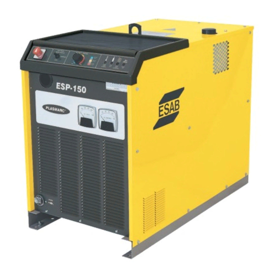
SECTION 2 DESCRIPTION Figure 1 - ESP-150 ESP-150 POWER SUPPLY SPECIFICATIONS Input Voltage ............. 380-400 / 415 Vac, 3 Phase 50/60 Hz Input Current ..............78A @ 380-400V, 71A @ 415V Power Factor ......................54% Output Current Rating ....... 150 Amps (40% Duty), 110A (100% Duty) Output Voltage ........ - Page 8 SECTION 2 DESCRIPTION PT-26 Technical Specifications (Plasma Gas) Type of Gas , Air, AR-H Pressure 100 psig (6.9 bar) Flow 240 cfh (6.8 M Purity Required - 99.5% min., N -99.995% min., Air - clean and dry Recommended Liquid Cylinder Service Regulators Inert Gas R-76-150-580LC...
- Page 9 SECTION 2 DESCRIPTION ESP-150 CE PLASMA CUTTING PACKAGES 0558003473 ESP-150 CE PT26 50' 70D AIR 0558003475 ESP-150 CE PT26 50' 90D AIR Part No. Description Qty. Part No. Description Qty. 0558002717 ESP-150 CONSOLE, CE 0558002717 ESP-150 CONSOLE, CE 0558002209 PT-26 70DEG 50'...
- Page 10 SECTION 2 DESCRIPTION...
-
Page 11: Installation
ELECTRIC SHOCK CAN KILL! Precau- tionary measures should be taken The ESP-150 Power Source is equipped with one lifting eye that enables to provide maximum protection hoisting the unit. Be sure the lifting device has adequate capacity to lift the against electric shock. -
Page 12: Primary Input Electrical Connections
SECTION 3 INSTALLATION B. PRIMARY INPUT ELECTRICAL CONNECTIONS 1. A line (wall) disconnect switch, with fuse or circuit breakers, should be pro- Precautionary measures should be taken to provide maximum protec- vided at the main power panel. See Fig. 3. The primary power leads should be tion against electrical shock. - Page 13 SECTION 3 INSTALLATION ELECTRIC SHOCK CAN KILL! Precau- 2. 50 Hz Models - As shipped from the factory, the ESP-150 is configured for tionary measures should be taken the highest connectable voltage. If using other input voltages, the links on the to provide maximum protection against electric shock.
- Page 14 SECTION 3 INSTALLATION 3. Safety codes specify that the Power Cable GROUND wire be the last to break connection should the cable be pulled out of the unit. Be sure to cut and strip wire as shown in Figure 6. Before making any connections to the power source output termi- nals, make sure that all primary in-...
- Page 15 INSTALLATION Control Mode Selection for Operation with Remote Plumbing Box The ESP-150 is supplied from the factory with Plug P45 connected to the J4 (MAN) receptacle (torch gases and torch connected directly to the ESP-150 power source). If the unit is to be used with a remote plumbing box, move P45 to the J5 (MECH) receptacle.
-
Page 16: Torch Connections
Remote Hand Switch, ESAB part number 2075600, to the Torch Switch Receptacle on the hook-up panel in the front of the ESP-150 console. Fig. 11. b. If a PT-26 In-line Torch is being used in a mechanized installation with a CNC device, see Fig. -
Page 17: Gas Supply Connections
2. Connect the gas hoses to the regulators and to the proper fittings (Adaptors: 74S76, Air; 19X54, Ar/H ) on the rear panel of the ESP-150. Connections should be wrench tight including those that are plugged. (Fig. 14) (3) Air Filter Regulators P/N-36932 Fig. -
Page 18: Work And Earth Connections
SECTION 3 INSTALLATION F. WORK and EARTH CONNECTIONS 1. Connect terminal lug end of the work cable assembly to stud on lower left corner of front panel. Nut should be wrench tight. (Fig. 6). Electrically con- nect work cable to work piece. The connection must be made to a clean, exposed metal surface free of paint, rust, mill scale, etc. - Page 19 SECTION 3 INSTALLATION...
- Page 20 SECTION 3 INSTALLATION...
-
Page 21: Operation
CONTROLS AND INDICATORS The status lights located on the front of the top lid of the ESP-150 console provide the conditions of the circuitry during a normal plasma arc cutting operation. By knowing the proper sequencing of events and by observing the status lights one can troubleshoot the console in a short time to minimize downtime. -
Page 22: Esp-150 Adjustments
Keep side panels closed 2. Place the ESP-150 GAS MODE and POWER switches in the OPERATE when unit is energized. Also make and OFF positions. sure you are adequately protected before you start cutting —... - Page 23 Position the ESP-150 at least 10 feet (3 meters) from the cutting area. Sparks and hot slag from the cutting operation can damage the unit. Fig. 16 - Effect of Cutting Speed With a positive cut angle, the top dimension is slightly less than the bottom dimension.
-
Page 24: Standoff And Cut Quality
SECTION 4 OPERATION STANDOFF AND CUT QUALITY Standoff (Arc Voltage) has a direct influence on cut quality and squareness. It is recommended that prior to cutting , that all cutting parameters are set to the manufacturer's suggested conditions. Refer to the Process Tables for recom- mendations. - Page 25 SECTION 4 OPERATION Fig. 19 - Arc Voltage Too High (Positive Cut Angle) Correct Cutting Speed Positive Cut Angle Rounded Top Edge VOLTAGE More Dross Top Dross (+) CUT END VIEW Cut Face Smooth CUT FACE Fig. 20 - Arc Voltage Correct Correct Cutting Speed No Top Dross Square Top Edge...
-
Page 26: Dross Formation
SECTION 4 OPERATION DROSS FORMATION Cutting speed, gas selection and variations in metal composition contribute to dross formation. The correct cutting standoff also has an influence on dross for- mation. If the arc voltage is set too high, the cut angle becomes positive. In addi- tion, dross forms on the bottom edge of the part. -
Page 27: Common Cutting Problems
The following is a listing of common cutting problems and the probable cause. If Tripped circuit breaker (located un- problems are determined to be caused by the ESP-150, refer to the maintenance der the top hinged cover) may indi- section of this manual. If the problem is not corrected after referring to the main- cate dangerous high voltage existed tenance section, contact your ESAB representative. -
Page 28: Standard Conditions
SECTION 4 OPERATION STANDARD CONDITIONS The cutting speeds and conditions in the following tables were selected to give the best quality with a particular gas combination at a specific current. Consumables - Refer to PT-26 Torch manual for recommended parts for these conditions. - Page 29 SECTION 4 OPERATION Table 3 - PT-26 Aluminum Cutting Data Material Travel Cutting Start Gas Plasma Gas Shield Gas Type-Thickness Speed Height Type/Pressure Type/Pressure Type/Pressure Current in.(mm) ipm(M/m) psi(bar) psi(bar) psi(bar) (Amps) in.(mm) AL-1/4 (6.35) 112 (2.84) 5/16 (8) H-35 or N H-35 - 50 (3.45) Air - 50 (3.45) 30 (2.1)
-
Page 30: Recommended Gas And Current
SECTION 4 OPERATION RECOMMENDED GAS AND CURRENT The following provide the recommended gas and cur- rent selection for common metals to obtain the best cutting results. STAINLESS STEEL CARBON STEEL 1/8" (3.2mm) 1/8" (3.2mm) and Thinner 50 - 65 Amps, N Plasma/N and Thinner 50 / 65 Amps, Air...
Need help?
Do you have a question about the ESP-150 and is the answer not in the manual?
Questions and answers