Table of Contents
Advertisement
Advertisement
Table of Contents
Troubleshooting

Related Manuals for ESAB ESP-200


Summary of Contents for ESAB ESP-200
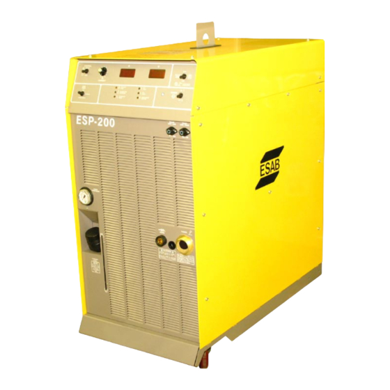
- Page 1 ESP-200 Plasmarc Cutting System Instruction Manual F15-462-C 02 / 2008...
-
Page 2: User Responsibility
Be sure thIs InForMatIon reaChes the operator. You Can get extra CopIes through Your supplIer. CautIon these InstruCtIons are for experienced operators. If you are not fully familiar with the principles of operation and safe practices for arc welding and cutting equipment, we urge you to read our booklet, “precautions and safe practices for arc Welding, Cutting, and gouging,”... -
Page 3: Table Of Contents
taBle oF Contents section / title page seCtIon 1 saFetY ............................ 5 seCtIon 2 DesCrIptIon ................................. 7 seCtIon 3 InstallatIon ..............................11 seCtIon 4 operatIon ................................23 seCtIon 5 CuttIng qualItY ....................... 61 seCtIon 6 MaIntenanCe........................67 seCtIon 7 trouBleshootIng......................73 seCtIon 8 replaCeMent parts ...................... - Page 4 Brand name or trade mark Fabrikatnamn eller varumärke ESAB Type designation etc. Typbeteckning etc. ESP-200 Console - 36974 Manufacturer or his authorised representative established within the EEA Name, address, telephone No, telefax No: Tillverkarens namn, adress, telefon, telefax: ESAB AB Esabvägen, SE-695 81 Laxå, Sweden...
-
Page 5: Safety Precautions
Users of ESAB welding and plasma cutting equipment have the ultimate responsibility for ensuring that anyone who works on or near the equipment observes all the relevant safety precautions. Safety precautions must meet the requirements that apply to this type of welding or plasma cutting equipment. The following recommendations should be observed in addition to the standard regulations that apply to the workplace. -
Page 6: Protect Yourself And Others
seCtIon 1 saFetY preCautIons WelDIng anD plasMa CuttIng Can Be InJurIous to YourselF anD WarnIng others. taKe preCautIons When WelDIng or CuttIng. asK For Your eMploYer’s saFetY praCtICes WhICh shoulD Be BaseD on ManuFaCturers’ haZarD Data. WARNING WARNING eleCtrIC shoCK - Can kill. Arc welding and cutting can be injurious to yourself and others. -
Page 7: Description
2.1 Introduction The ESP 200 Power Console is designed for plasma mechanized or hand cutting applications. It can be used with other ESAB products such as the PT-26 and PT-600 torches, an optional plumbing box and a remote set-up pendant. - Page 8 2 DesCrIptIon eleCtrIC shoCK Can KIll! WarnIng use oF torChes not DesIgneD For thIs Console CoulD result In a haZarDous eleCtrIC shoCK. use onlY torChes DesIgneD For the esp-200 Console. Dimensions and Weight 44 in. (1100mm) 42 in. (1050mm) 22 in.
- Page 9 ESP Plumbing Box Weight = 38 lbs Remote Setup Pendant Weight (17kg) 1lb (0.9kg) esp-200 options and accessories ESP-200 Plumbing Box ................................P/N 22000 Remote Setup Pendant .................................P/N 37145 Water Hoses and Cables for options 25 ft. 50 ft. 75 ft.
-
Page 10: Note 1: Requires Adapter P/N 19X54 (Order Separately
seCtIon 2 DesCrIptIon 2.5 gas hoses Gas Type 25 ft. (7.6m) 50 ft. (15.2m) 75 ft. (22.8m) 100 ft. (30.4m) 150 ft. (45.7m) Nitrogen 33122 33123 33124 33125 33126 Oxygen (blue) 0558002973 0558002974 0558002975 0558002976 0558002977 Argon/Hydrogen (H-35) 33122 (note 1) 33123 (note 1) 33124 (note 1) 33125 (note 1) - Page 11 2 DesCrIptIon 2.7 Basic packages The ESP-200 system is available as a pre-engineered package or can be ordered as individual parts as listed. Basic Packages include: • ESP-200 Console • Plasma Torch • Appropriate regulators for the gases indicated •...
- Page 12 seCtIon 2 DesCrIptIon...
-
Page 13: Installation
Plan for top panel and side panels having to be removed for maintenance, cleaning and inspection. • Locate the ESP-200 relatively close to a properly fused electrical power supply. • Keep area beneath power source clear for cooling air flow. -
Page 14: Electric Shock Can Kill
Wall DIsConneCt sWItCh to turn poWer oFF. 3.4.1 primary power specifications ESP-200 is a 3-phase unit. Input power must be provided from a line (wall) disconnect switch that contains fuses or circuit breakers in accordance to local or state regulations. - Page 15 seCtIon 3 InstallatIon 3.4.2 primary power hookup procedure The following procedure explains the proper in- stallation steps for connecting primary electrical power to the plasma console. NOTE: Safety codes specify the power ground wire be the last connection to break should the cable be pulled out of the unit.
-
Page 16: Gas Input Connections
Install filter regulators if using shop air for any of three process gases. (Start, Shield, Cut Gas) Filter: 5 micron Regulator: 5 to 125 PSI (0.35 to 8.63 bar) ESAB P/N 30338 View as shipped Note: Refer to your torch manual for proper pressure/flow settings. - Page 17 • Have a qualified person check the output bus bars (positive and nega- tive) with a voltmeter. 3.5.1 pt-26 and esp-200 output Cables, hoses and adapters (customer supplied) Hose and cable lengths vary depending on system. • Coolant Return (pilot arc cable inside) •...
- Page 18 Can KIll! WarnIng turn oFF prIMarY Input poWer at the Wall DIsConneCt Box BeFore MaKIng anY ConneCtIons to the esp-200. PT-26 Plasmarc Torches Both hand and mechanized torches connect the same. The mechanized torch requires an auxiliary arc ON switch that connects the same as the arc ON switch of the hand held torch.
- Page 19 seCtIon 3 InstallatIon e. Connect shield gas hose (if used) to the shield gas fitting (‘B’ size left-hand thread- ed male fitting). Hose has left-hand female fitting. Connect plasma cut gas (‘B’ size right-hand threaded female fitting). Hose has right-hand male fitting. g.
- Page 20 seCtIon 3 InstallatIon 2. Re-install side panel. 3. Connect work cable to work connection on front panel. Insert and rotate clockwise until tight. Approximately ½ turn. 4. Assemble filter regulator and mounting bracket (P/N 30338) to the upper right corner on rear panel (as viewed from the rear).
- Page 21 seCtIon 3 InstallatIon Work ground to work piece Work ground to cutting table 7. Connect the other end of work cable to workpiece or cutting table. Connection must be made to a clean, exposed metal surface, free of paint, rust, mill scale, etc. eleCtrIC Current Is haZarDous.
- Page 22 seCtIon 3 InstallatIon 3.5.3 pt-26 hand and Mechanized torch Interconnection Diagram...
- Page 23 seCtIon 3 InstallatIon PT-26 Interconnecting Diagram Legend Shield Gas Switch Lead (the switch lead connects to a auxiliary arc ON switch box when using the PT-26M torch) Coolant Supply/Electrode Current Pilot Arc/Coolant Return Plasma Gas Work Lead Work Piece Earth Ground PT-26 Hand Torch PT-26 Mechanized Torch Shield Gas Supply...
- Page 24 3 InstallatIon Connecting pt-19xls or pt-600 plasma torches to esp-200 Console and options 3.6.1 pt-19xls or pt600 and esp-200 output Cables, hoses and adapters (customer supplied) PT-19XLS and PT-600 with ESP-200 Plumbing Box/ESP-200 Lengths vary depending on system. •...
- Page 25 Thread cable adapter (P/N 36743) into coolant supply/electrode cable connection. note: Use of the ESP-200 plumbing box requires separation of coolant supply and electrode cable. The elec- trode cable is inside the coolant supply hose for the PT-26 torch interface. (The PT-26 does not use a plumbing box.)
- Page 26 seCtIon 3 InstallatIon c. Attach coolant hoses (see Description, Section 2 for part numbers) to console and plumbing box. note: The supply and return coolant hoses between the ESP console and plumbing box have identical fittings. It is possible to cross connect these hoses. Be very careful to connect console connection labeled “Pilot Arc”...
- Page 27 Move the P5 plug from J5 position to J6 position. This is to setup the plasma console for a remote plumbing box. P5/P6 location Move connector 2. Re-install side panel of the ESP-200 Console. 3. Connect work cable to work connection on the front panel of console. Insert and rotate clockwise until tight. Approximately ½ turn.
- Page 28 3 InstallatIon 3.6.3 Input connections to esp-200 plumbing Box eleCtrIC shoCK Can KIll! WarnIng turn oFF prIMarY Input poWer at the Wall DIsConneCt Box BeFore MaKIng anY ConneCtIons to the esp-200. 1. Connect cooling water supply (from Console connection labeled “TORCH”) hose to “COOLING WATER IN”.
- Page 29 seCtIon 3 InstallatIon Connect start gas, shield gas and cut gas hoses from gas supply to the appropriate labeled connection points on the back of the plumbing box. (When using a remote plumbing box, gases by-pass the power console and go directly to the plumbing box.) note: Gas supplies (including air) should be filtered prior to entering the plumbing box.
- Page 30 seCtIon 3 InstallatIon Remote Setup Pendant 3.6.4 remote setup pendant Installation TB5 in the plumbing box The Set-up Pendant/Panel cable is a 6 conductor cable. Connect: TB5-1 to TB1-1 TB5-2 to TB1-2 TB5-3 to TB1-3 TB5-4 to TB1-4 Set-up Pendant Plumbing Box TB5-5 to TB1-5 TB5-6 to TB1-6...
- Page 31 seCtIon 3 InstallatIon Plumbing box fully connected (including setup pendant)
- Page 32 seCtIon 3 InstallatIon...
- Page 33 seCtIon 3 InstallatIon PT-600 (and 19XLS) Interconnecting Diagram Legend Electrode Cable Coolant Return Hose Pilot arc Cable Coolant Supply Hose Work Cable Work Piece Earth Ground Plasma Torch (PT-600 shown) Shield Gas In (from gas supply) Setup Pendant (Remote) Cut gas In (from gas supply) Start Gas (from gas supply) Height Control Torch Bundle (Cooling Water: Supply and Return, Current: Pilot Arc and Electrode)
- Page 34 seCtIon 3 InstallatIon 3.7 Coolant Installation eleCtrIC Current Is haZarDous. WarnIng It Is IMportant to haVe a gooD earth grounD ConneCteD to the WorKpIeCe or CuttIng taBle. Commercial antifreeze Will Cause torch to Malfunction. CautIon use special torch coolant. p/n 156F05 Due to high electrical conductivity, Do not use tap water or com- mercial automotive type antifreeze for torch cooling.
-
Page 35: Operation
seCtIon 4 operatIon 4.1 Introduction – operational safety eleCtrIC shoCK Can KIll! DIsConneCt Current supplY at Wall DIsConneCt BeFore ser- Danger VICIng Console, torCh or pluMBIng Box. • Do not operate console or plumbing box with any covers removed/ open. •... -
Page 36: Console Controls
4 operatIon 4.2 operating the esp-200 Console 4.2.1 Console Controls Pilot Arc High/Low Switch Cutting Voltage and Cutting Current Meters Output Current Control Remote/Panel Selection Switch Gas Test Switch Fault Lights Main Power Switch Pilot Arc Switch Used to select pilot arc current range. HIGH position is used for most cutting applications. - Page 37 seCtIon 4 operatIon Gas Test Switch Cut – Allows for setup of cut gas pressure and flow. Start/Shield – Setup of gas pressures and flows. Operate – Default position – Must be in this position for cutting. Fault Indicator Lights •...
- Page 38 seCtIon 4 operatIon 4.2.2 remote setup pendant Remote setup pendant switch is identical in function to the Gas Test Switch on the console. Pendant has a three position switch: Position CUT – Temporarily allows cut gas to flow to preset pressure before operation. Cut gas pressure is displayed on the top digital meter.
-
Page 39: Sequence Of Operation
seCtIon 4 operatIon 4.3 sequence of operation 1. Apply power by closing the line (wall) switch. Main power light will not illuminate until console power switch is turned ON. Fault light should flash and go out. Apply Power 2. Select the Panel/Remote setting. If current is controlled from cutting machine CNC, place switch to Remote position. - Page 40 4.4 process Data for pt19xls/pt-26 and the esp-200 4.4.1 Introduction to Cut Characteristics The quality of a cut is judged by three primary characteristics;...
- Page 41 • Excellent - Bright and smooth • Good - Discolored, fairly smooth • Fair - Moderate roughness • Poor - Very rough 4.4.2 ConDItIon seleCtIon Charts for pt-19xls with esp-200 4.4.2.1 Carbon steel Current 50-65A 100A 100A 150A 150A 200A...
-
Page 42: Stainless Steel
seCtIon 4 operatIon 4.4.2.2 stainless steel Current 50-65A 50-65A 100A 100A 100A 150A 150A 150A 200A 200A 200A Plasma gas H-35 H-35 Shield gas 1,6mm E 1 P G 1 G (1/16 in.) 3,2mm E 1 P P 1 G (1/8 in.) 6,4mm E 5 P... - Page 43 seCtIon 4 operatIon 4.4.2.3 aluminum Current 50-65A 50-65A 100A 150A 150A 200A 200A 200A Plasma Gas H-35 H-35 Shield Gas 1,6mm E 1 G E 2 F (1/16 in.) 3,2mm E 1 G E 2 F (1/8 in.) 6,4mm E 1 G E 2 F E 1 G E 2 G...
- Page 44 The cutting speeds and conditions in the following tables were selected to give the best quality with a particular gas com- bination at a specific current. They are unique to the ESP-200/PT19XLS combination because of restrictive gas ports built into the power supply •...
- Page 45 seCtIon 4 operatIon 4.4.3.3 process Data at 100 amps (pt-19xls and pt-600) pierce start gas Cutting plasma gas Material travel shield gas height height type/pressure type-thickness Current Voltage type/pressure type/pressure speed in.(mm) psi((bar) in.(mm) (Volts) psi (bar) in.(mm) (amps) ipm(M/m) psi(bar) CS - 3/16 (4.8) 150 (3.8) 3/8 (9.6)
- Page 46 seCtIon 4 operatIon 4.4.3.4 process Data at 150 amps (pt-19xls and pt-600) pierce travel Cutting start gas plasma gas Material shield gas Voltage height height type-thickness Current speed type/pressure type/pressure type/pressure (Volts) in.(mm) ipm(M/m) in.(mm) psi(bar) in. (mm) (amps) psi(bar) psi(bar) CS - 3/16 (4.8) 160 (4.1) 3/8 (9.6)
- Page 47 seCtIon 4 operatIon 150 amp Data (pt-19xls and pt-600) Continued Material pierce Cutting shield gas travel start gas plasma gas Voltage type-thickness height height type/pressure Current speed type/pressure type/pressure (Volts) in. (mm) in.(mm) in.(mm) psi(bar) (amps) ipm(M/m) psi(bar) psi(bar) SS - 3/16 (4.8) 200 (5.1) 3/8 (9.6) 1/8 (3.2) - 25 (1.7)
- Page 48 seCtIon 4 operatIon 4.4.3.5 process Data at 200 amps (pt-19xls and pt-600) pierce Cutting start gas plasma gas shield gas Material travel height height Voltage type/pressure Current type/pressure type-thickness speed type/pressure in.(mm) (Volts) in.(mm) psi(bar) psi(bar) (amps) psi(bar) in.(mm) ipm(M/m) CS - 1/4 (6.4) 150 (3.8) 3/8 (9.6)
- Page 49 seCtIon 4 operatIon 200 amp Data (pt-19xls and pt-600) continued pierce shield gas Material Cutting travel start gas plasma gas height type/pressure type-thickness Current height speed type/pressure type/pressure Voltage in.(mm) psi(bar) in.(mm) (amps) in.(mm) ipm(M/m psi(bar) psi(bar) (Volts) AL - 1/4 (6.4) 180 (4.6) 3/8 (9.6) 3/16 (4.8)
- Page 50 4 operatIon 4.4.4 pt-26 plasma torch and esp-200 process Data 4.4.4.1 Carbon steel Material Current travel height start gas plasma gas shield gas type-thickness (amps) speed in.(mm) type/pressure type/pressure type/pressure in.(mm) ipm(M/m psi(bar) psi(bar) psi(bar) CS- 3,2 (1/8) 4,95 (195) 7,9 (5/16) Air –...
- Page 51 seCtIon 4 operatIon 4.4.4.2 aluminum Cutting Data (pt-26) Material Current travel height start gas plasma gas shield gas type-thickness (amps) speed in.(mm) type/pressure type/pressure type/pressure in.(mm) ipm(M/m psi(bar) psi(bar) psi(bar) AL- 6,35 (1/4) 3,56 (140) 7,9 (5/16) Air - 2,1 (30) Air - 3,45 (50) Air - 3,45 (50) AL- 7,9 (5/16)
- Page 52 seCtIon 4 operatIon 4.4.4.3 stainless steel Cutting Data (pt-26) Material Current travel height start gas plasma gas shield gas type-thickness (amps) speed in.(mm) type/pressure type/pressure type/pressure in.(mm) ipm(M/m psi(bar) psi(bar) psi(bar) SS- 6,35 (1/4) 3,8 (150) 7,9 (5/16) Air - 2,76 (40) Air - 4,14 (60) Air - 3,45 (50) SS- 9,5 (3/8)
- Page 53 seCtIon 4 operatIon 4.4.5 recommended gas and Current The following provide the recommended gas and current selection for common metals to obtain the best cutting results. 4.4.5.1 Carbon steel 1/8” (3.2mm) and Thinner • 50 / 65 Amps, Air Plasma/Air Shield. 3/16 – 1/2 (4.8-12.7mm) • 100 Amps, O2 Plasma/Air Shield.
- Page 54 seCtIon 4 operatIon 4.4.5.3 aluminum 1/4” (6.4mm) and Thinner • 50/65 Amps, N2 Plasma/N2 Shield usually produces fairly smooth, dross free cuts. • 50/65 Amps, Air Plasma/Air Shield produces much rougher cut surfaces. 1/4” (6.4mm) and Thicker • 200 Amps, H-35 Plasma/N2 Shield produces best results with little or no dross under 1”(25.4mm) thickness and excellent surface quality on 1/4 to 1/2” (6.4 - 12.7mm) material. Surface is good on thicker materials. • 200 Amps, Air Plasma/Air Shield produces fair surfaces on 3/4”(19mm) and thinner material with very light dross to dross free conditions on 1/2” (12.7mm) and thinner. •...
- Page 55 seCtIon 4 operatIon 4.4.6 Maximum economy Conditions The conditions outlined in the following tables will minimize the operating cost for common metals: • Use AIR as PLASMA and SHIELD GAS. • Achieve maximum cutting speed without regard to cut quality. Pilot Arc - HIGH Current - 200 Amps Start Gas - AIR @ 25 psig Plasma Gas - Air @ 45 psig (3.1 bar) for CS, 50 psig (3.5 bar) for SS &...
- Page 56 seCtIon 4 operatIon 4.4.7 pt-19xls and pt-600 Kerf Values 100 Amperes Material Thickness (mm) Material Thickness (inches)
- Page 57 seCtIon 4 operatIon 150 Amperes Material Thickness (mm) Material Thickness (inches)
- Page 58 seCtIon 4 operatIon 200 Amperes Material Thickness (mm) Material Thickness (inches)
-
Page 59: Maintenance
5.2 Inspection and Cleaning Frequent inspection and cleaning of the ESP-200 and related equipment are recommended for safety and proper operation. Consider the following during inspection and cleaning: •... - Page 60 • Periodically bleed all water from the air filter/regulator trap. 5.3 gas Manifold pressure switches Newer ESP-200 consoles are equipped with nonadjustable preset gas manifold pressure switches. Older ESP-200 consoles have adjustable pressure switches. Both type switches are preset for: •...
- Page 61 seCtIon 5 MaIntenanCe 5.3.1 pressure switch adjustment procedure Pressure Adjusting Wheel 1. Turn main power switch OFF. 2. Remove right side panel 3. Turn wheel: • Counterclockwise to increase pressure • Clockwise to decrease pressure 4. Replace panel. 5. Resume operation. Gas Manifold 5.3.2 gas Manifold with non-adjustable pressure switches (reference) N o n a d j u s t a b l e Solenoids Pressure Switches...
- Page 62 seCtIon 5 MaIntenanCe 5.4 Cooling Water Flow switch Water Flow Switch cleaning may be indicated if excessive coolant contamination is noticed or Coolant Fault light illumi- nates. It is not necessary to remove the flow switch from the console for notICe cleaning.
- Page 63 6. Remove piston. 7. Clean all parts with mild soap solution and rinse thoroughly with clean water. 8. Reassemble in reverse order. note: Use only ESAB replacement parts. Piston Plug Spring Piston Flow Switch Body...
- Page 64 seCtIon 5 MaIntenanCe 5.5 spark gap high Frequency Interference Can Damage Machine electronic Com- ponents CautIon potentially damaging high frequency interference may result from increasing the spark gap beyond recommendation. this electrical in- terference may find its way to pc boards in the electronics cabinet or Vision control.
- Page 65 seCtIon 5 MaIntenanCe The high frequency start box is accessed by removing the right side panel. note: Do not making any adjustments to this box if using the ESP plumbing box. The plasma starting arc originates from the plumbing box. Top view of console starter Spark gap assembly Set gap to 0.040”...
- Page 66 seCtIon 5 MaIntenanCe...
-
Page 67: Troubleshooting
seCtIon 6 trouBleshootIng 6.1 Introduction eleCtrIC shoCK Can KIll! WarnIng ensure all prIMarY poWer to MaChIne has Been externallY DIsConneCteD. open lIne (Wall) sWItCh BeFore atteMptIng In- speCtIon or perForMIng WorK InsIDe the plasMa Console or pluMBIng Box. CapaCItors Can store hIgh Voltages. WarnIng DIsConneCtIng plasMa Console Does not ensure CapaCItors are De-energIZeD. - Page 68 seCtIon 6 trouBleshootIng 6.3 Front panel Fault lights Fault Indicator Lights • Coolant Flow – Will show low coolant flow. The light will briefly show a fault when console is turned on and then go out. • Plasma Gas Pressure -- fault indicator – low plasma gas pressure. Torch will not fire when indicated. •...
-
Page 69: Troubleshooting Guide
seCtIon 6 trouBleshootIng 6.4 troubleshooting guide hIgh Voltages Can Cause serIous InJurY or Death! WarnIng Voltages In plasMa CuttIng equIpMent are hIgh enough to Cause serIous InJurY or Death. onlY traIneD teChnICIans shoulD atteMpt DIagnosIs anD repaIr oF thIs MaChInerY. avoid damaging your voltmeter. - Page 70 seCtIon 6 trouBleshootIng problem possible Cause Corrective action Power Source Temperature Fault indi- Poor ventilation at rear of console. Make sure that there is 2 feet of cator is ON. clearance on each side of console. Open thermal switch. With power OFF, check each ther- mal switch.
- Page 71 seCtIon 6 trouBleshootIng problem possible Cause Corrective action LEDX on MOD1 not ON. LEDX on MOD2 not ON. LEDX on MOD2 not ON when torch switch is depressed or start signal is sent. Arc does not transfer to work. Open connection between the 1a) Check continuity of WORK cable console WORK connector and the and clamp.
- Page 72 seCtIon 6 trouBleshootIng torch and Cut quality note: This is offered as a general guide. Refer to your torch manual for specifics on your equipment Problem Possible Cause Corrective Action Reduced Electrode Life 1) Skeleton cutting 1) Cutting skeletons to facilitate their Removal from the table can ad- versely affect electrode life by: a) Causing the torch to run off the...
- Page 73 seCtIon 6 trouBleshootIng Problem Possible Cause Corrective Action Reduced Electrode Life 1) Diving 1). Diving is usually caused by a change in arc voltage when an automatic height control is in use. Diving can result in damage to the nozzle. Usu- ally, the voltage change is the result of a change of direction or speed to negotiate a corner, failure to disable...
- Page 74 seCtIon 6 trouBleshootIng Problem Possible Cause Corrective Action Poor Cut Quality 1. Gas selection 1. Refer to gas selection section. Refer to your torch manual 2. Torch alignment to work 2. Verify and correct torch alignment (verti- for more details. cally).
- Page 75 seCtIon 6 trouBleshootIng Problem Possible Cause Corrective Action Torch Fails to Fire 1. Start gas too high. 1. Lower start gas flow. 2. Coolant flow switch not satisfied. 2. a). Pump pressure too low, should be 90 - 100 psig. b).
- Page 76 seCtIon 6 trouBleshootIng...
-
Page 77: Replacement Parts
To ensure proper operation, it is recommended that only genuine ESAB parts and products be used with this equipment. The use of non-ESAB parts may void your warranty. Replacement parts may be ordered from your ESAB Distributor. - Page 78 7 replaCeMent parts 7.3 esp-200 p/n 36324 -- outside View – Front...
- Page 79 seCtIon 7 replaCeMent parts Item No Part Number Description Circuit Symbol 952182 Spout –Remote Filler See Below Gauge –200PSI 636702 Switch – Toggle DPDT 3pos 15A 125V 634518 Switch – Toggle DPDT 2pos 15A 2062018 POT 10K 2W 954619 Overlay 200I 951061 Meter –...
- Page 80 seCtIon 7 replaCeMent parts 7.4 outside View- Back C E Unit Only...
- Page 81 seCtIon 7 replaCeMent parts Item No Part Number Description Circuit Symbol 639582 Plug and Chain B/I—G M RH BRS 13730763 Plate -- Serial 952137 Fuse – 600V 15A Fast acting 950829 Circuit Breaker 3 AMP CB1,2 952595 Strain Relief 23610197 Hole Plugs 2133514 Hole Plug (restart switch on CE units)
- Page 82 seCtIon 7 replaCeMent parts 7.5 Front View with Front panel removed...
- Page 83 seCtIon 7 replaCeMent parts Item No Part Number Description Circuit Symbol 950760 Relay Enclose DPDT 24 VAC 10A K4,5,6 2080196 Relay Enclose 3PDT 120VAC 673168 Terminal Block 13pos 20A 2234521 Plug – 16pos P4,5,6, Mod1 P1, Mod2 P1 952252 Sensor --Current 2234520 Plug –...
- Page 84 seCtIon 7 replaCeMent parts 7.6 right Inside View...
- Page 85 seCtIon 7 replaCeMent parts Item No Part Number Description Circuit Symbol 950487 Term Blk 2pos 0558005165 Control Xfrmr 35759 w/ Terminals 17300008 Resistor 8ohm 300W R7,8,9,10 952251 Contactor 3 pole 150A 952026 Term Blk 7pos 25A 12-18 AWG 952198 Term Block 145 A 36910 Gas Manifold 38131...
- Page 86 seCtIon 7 replaCeMent parts 7.7 left side View 9 10...
- Page 87 seCtIon 7 replaCeMent parts Item No Part Number Description Circuit Symbol 36349 Auto XFMR 17315247 Resistor 4.7K OHM 12W 950627 Capacitor 4200uf 350VAC 951109 Housing Contact 12pos J9,10 2062367 Recpt Housing 12pos nylon P9,10 673676 Fan Blade 2062334 Motor --Fan 952002 Core -- Saturable 38094...
- Page 88 seCtIon 7 replaCeMent parts 7.8 Back and top Inside View R ef. R ef.
- Page 89 seCtIon 7 replaCeMent parts Item No Part Number Description Circuit Symbol 2234891 Plug 10pos Mod1 P3,4 Mod2 P3,4 37243 Module –Power CE Mod2 37100 Module – Power CE Mod1 2017483 Fuse N-T Delay 1.00A 250V 995103 Terminal Block 24pos 15A 13735961 Heat Exchanger...
- Page 90 seCtIon 7 replaCeMent parts 7.9 Cross section and gas Manifold T O G A UG E V iew A - A...
- Page 91 seCtIon 7 replaCeMent parts Item No Part Number Description Circuit Symbol 951215 Motor carb 1/3 HP 951347 Pump Carb w/Strainer 13735961 Heat Exchanger 36910 Manifold, Gas Control Assembly 0558002345 Pressure Switch 17 PSI PS1,2 0558002346 Pressure Switch 22 PSI 3389 Adapter B/OXY m ¼...
- Page 92 seCtIon 7 replaCeMent parts 7.10 remote setup pendant p/n 37145...
- Page 93 seCtIon 7 replaCeMent parts Item No Part Number Description 951086 Handle 32282GY Cover 951474 Switch Boot 527376 Strain Relief 2062151 Locknut 952026 Term Blk 7pos 25A 12—18AWG 37239GY Base 636702 Switch – Toggle DPDT 3pos 15A 125V 952625 Display – LCD 4—20mA...
- Page 94 7 replaCeMent parts 7.11 esp-200 plumbing Box p/n 22000 -- Inside and h.F. Box...
- Page 95 seCtIon 7 replaCeMent parts Item No Part Number Description Circuit Symbol 56997963 Board, PC Arc Voltage PCB1 674969 Filter Board PCB2 37232 Hose Assembly – Plasma Gas 37233 Hose Assembly – Shield Gas 952026 Term Block 7pos 25A 12—18AWG 952624 Transducer Pressure 4—20mA TD1,2 673085...
- Page 96 seCtIon 7 replaCeMent parts 7.12 gas Manifold – plumbing Box p/n 0558001952...
- Page 97 seCtIon 7 replaCeMent parts Item No Part Number Description Circuit Symbol 0558002345 Pressure Switch – 17 PSI 952087 Elbow – Male Swivel 90 deg 1/8 NPT 0558002346 Pressure Switch – 22 PSI 3389 Adapter CPLR B/OXY M ¼ NPTM 36357 Manifold 0558006864 Valve Solenoid...
- Page 98 7 replaCeMent parts 7.13 esp-200 plumbing Box – outside and Cooling Water Connections...
- Page 99 seCtIon 7 replaCeMent parts Item No Part Number Description Circuit Symbol 33053 Strain Relief 951188 Locknut 993952 Conn Box Recpt ^FS Shell 18 33033 Adapt B/A-W M ¼ NPTM BKHD 58V58 Adapt B/I-G F ¼ NPTM BKHD 526652 Strain Relief 2062151 Locknut 527376...
- Page 100 notes...
-
Page 101: Revision History
Revision of 09/2004 - changed p/n 36911, wire kit to: p/n 0558005165, contrl xfrmr 35679 w/terminals in the replace- ment parts section 7. Revision of 02/2005 - updated schematic 37105 (ESP-200 CE) per change notice #043269. Revision of 08/2005 - converted manual to Indesign format, updated schematics per CN-053071. - Page 102 ItalY north and south america MalaYsIa austrIa ESAB Saldatura S.p.A. argentIna ESAB (Malaysia) Snd Bhd ESAB Ges.m.b.H Mesero (Mi) CONARCO Shah Alam Selangor Vienna-Liesing Tel: +39 02 97 96 81 Buenos Aires Tel: +60 3 5511 3615...
Need help?
Do you have a question about the ESP-200 and is the answer not in the manual?
Questions and answers