
Related Manuals for Thermal Dynamics CE CutMaster 80XL


Summary of Contents for Thermal Dynamics CE CutMaster 80XL
- Page 1 PLASMA CUTTING POWER SUPPLY CE CutMaster 80XL A-02218 Service Manual December 4, 2002 Manual No. 0-2725...
- Page 3 Manufacturer assumes no liability for its use. Plasma Cutting Power Supply CE Cut Master 80XL Service Manual Number 0-2725 Published by: Thermal Dynamics Corporation 82 Benning Street West Lebanon, New Hampshire, USA 03784 (603) 298-5711 www.thermal-dynamics.com Copyright 1998 by Thermal Dynamics Corporation All rights reserved.
-
Page 4: Table Of Contents
TABLE OF CONTENTS SECTION 1: GENERAL INFORMATION ....................1 1.01 Notes, Cautions and Warnings ................ 1 1.02 Important Safety Precautions ................1 1.03 Publications ..................... 2 1.04 Note, Attention et Avertissement ..............3 1.05 Precautions De Securite Importantes .............. 3 1.06 Documents De Reference ................ - Page 5 TABLE OF CONTENTS (continued) SECTION 6: PARTS LISTS ........................6-1 6.01 Introduction ....................6-1 6.02 Ordering Information ................... 6-1 6.03 Major External Replacement Parts List ............6-2 6.04 Front Panel Replacement Parts List ............6-4 6.05 Left Side Internal Component Replacement Parts List ........ 6-6 6.06 Rear Panel Replacement Parts List .............
-
Page 7: General Information
SECTION 1: GASES AND FUMES GENERAL INFORMATION Gases and fumes produced during the plasma cutting process can be dangerous and hazardous to your health. 1.01 Notes, Cautions and Warnings • Keep all fumes and gases from the breathing area. Throughout this manual, notes, cautions, and warnings Keep your head out of the welding fume plume. -
Page 8: Publications
• Wear dry gloves and clothing. Insulate yourself from the work piece or other parts of the welding PLASMA ARC RAYS circuit. • Repair or replace all worn or damaged parts. Plasma Arc Rays can injure your eyes and burn your skin. •... -
Page 9: Note, Attention Et Avertissement
6. ANSI Standard Z49.2, FIRE PREVENTION IN THE USE ATTENTION OF CUTTING AND WELDING PROCESSES, obtain- able from American National Standards Institute, 1430 Broadway, New York, NY 10018 Toute procédure pouvant résulter l’endommagement du matériel en cas de non- 7. AWS Standard A6.0, WELDING AND CUTTING CON- respect de la procédure en question. - Page 10 • Eloignez toute fumée et gaz de votre zone de respira- • Ne touchez jamais une pièce “sous tension” ou “vive”; tion. Gardez votre tête hors de la plume de fumée portez des gants et des vêtements secs. Isolez-vous provenant du chalumeau. de la pièce de travail ou des autres parties du circuit de soudage.
-
Page 11: Documents De Reference
ultra-violets très forts. Ces rayons d’arc nuiront à vos 1.06 Documents De Reference yeux et brûleront votre peau si vous ne vous protégez pas correctement. Consultez les normes suivantes ou les révisions les plus récentes ayant été faites à celles-ci pour de plus amples •... - Page 12 9. Norme 70 de la NFPA, CODE ELECTRIQUE NA- TIONAL, disponible auprès de la National Fire Pro- tection Association, Batterymarch Park, Quincy, MA 02269 10. Norme 51B de la NFPA, LES PROCÉDÉS DE COUPE ET DE SOUDAGE, disponible auprès de la National Fire Protection Association, Batterymarch Park, Quincy, MA 02269 11.
-
Page 13: Declaration Of Conformity
Rigorous testing is incorporated into the manufacturing process to ensure the manufactured product meets or exceeds all design specifications. Thermal Dynamics has been manufacturing products for more than 30 years, and will continue to achieve excellence in our area of manufacture. -
Page 14: Statement Of Warranty
None Warranty repairs or replacement claims under this limited warranty must be submitted by an authorized Thermal Dynamics® repair facility within thirty (30) days of the repair. No transportation costs of any kind will be paid under this warranty. Transportation charges to send products to an authorized warranty repair facility shall be the responsibility of the customer. -
Page 15: Introduction
C. Customer/Operator Responsibilities It is the customer/operators’ responsibility to maintain the equipment and peripheral Accessories provided by Thermal Dynamics in good operating order in accordance with the procedures outlined in the Operating Manual, and to protect the equipment from accidental or mali- cious damage. - Page 16 INTRODUCTION Manual 0-2725...
-
Page 17: Introduction
SECTION 3: 3.03 Specifications/Design Features INTRODUCTION A. Power Supply Technical Specifications The following specifications apply to the Power Supply only: 3.01 Scope of Manual 1. Front Panel Controls The information in this Section is the same information ON/OFF Switch, RUN/SET Switch and Output Cur- contained in Section 2 of the Operating Manual. -
Page 18: Power Supply Options And Accessories
10. Overall Dimensions 18.9" (480 mm) High x 10" (254 mm) Wide x 23.5" (597 mm) Long Overall dimensions are with handle installed. B. Gas Regulator/Filter Assembly Specifications The following specifications apply to the Gas Regu- lator/Filter Assembly only: 1. Maximum input gas pressure 125 psi (8.6 bar) 2. -
Page 19: Service Troubleshooting Diagnostics
A. Piloting SECTION 4: Piloting is harder on parts life than actual cutting be- SERVICE cause the pilot arc is directed from the electrode to TROUBLESHOOTING the tip rather than to a workpiece. Whenever pos- sible, avoid excessive pilot arc time to improve parts DIAGNOSTICS life. -
Page 20: Troubleshooting Guide - General Information
NOTE 3. Excessive Dross Formation For basic troubleshooting and parts replacement a. Cutting speed too slow procedures refer to CE CutMaster 80XL Operat- ing Manual 0-2724. b. Torch standoff too high from workpiece c. Worn torch parts The advanced troubleshooting covered in this Service d. -
Page 21: Circuit Fault Isolation
C. How to use the Troubleshooting Guide Set the Power Supply controls as follows: ON/OFF switch to OFF. The following information is a guide to help the Service Technician determine the most likely causes for various RUN/SET switch to SET. symptoms. -
Page 22: Main Input And Internal Power Problems
D. Main Arc Test 6. Fuse blown inside Power Supply a. Replace internal Fuse. See Section 6, Parts Lists, Press the Torch Switch to establish a pilot arc. for replacement fuse catalog number. Bring the torch to within 1/8"-3/8" (3.2 - 9.5 mm) of the 7. - Page 23 C. AC indicator ON, TEMP indicator ON, System 5. Faulty gas solenoid circuit will not pilot a. Test gas solenoid circuit per Section 4.09-H; re- 1. Air flow through unit is restricted pair as necessary a. Provide adequate air flow (Refer to Operating F.
- Page 24 TP1 (GND) Pilot Output PC Board Logic PC Board A-01399 Pin 3 Pin 13 A-01391 Pin 1 G. Arc in torch without pressing torch switch; AC indicator ON; Gas flows; GAS and DC indicators 1. Faulty torch switch 4. Faulty Logic PC Board a.
-
Page 25: Pilot Arc Problems
4.07 Pilot Arc Problems CD PC Board Locate your symptom below: A. No gas flow; AC indicator ON; GAS and DC indicators OFF (Torch Switch must be pressed) Pin 4 1. Faulty hand torch parts or Logic PC Board Pin 5 Check torch switch enable indicator, D5, on the Logic PC Board. -
Page 26: Main Arc Problems
• Pilot indicator (D33) on the Logic PC Board is Pilot Output PC Board ON during pilot then OFF during main arc transfer • CSR indicator (D31) on the Logic PC Board is OFF during pilot then ON during main arc transfer A-01400 Wire #16... -
Page 27: Test Procedures
3. Faulty Logic PC Board Mounting Screws If torch tip is off the workpiece and the drag indi- cator, D35, on the Logic PC Board is still ON, then replace the Logic PC Board Handle 4.09 Test Procedures Leads Wrap The test procedures in this subsection are referenced in the troubleshooting section. - Page 28 C. Diode Testing Basics A-00306 Testing of diode modules requires a digital volt/ohmme- ter that has a diode test scale. Remember that even if the diode module checks good, it may still be bad. If in doubt, replace the diode module. 1.
- Page 29 6. Place main input power disconnect to OFF. E. Input PC Board Test 7. Reconnect wires to the input of the Main Contac- Locate the Input PC Board behind the EMC Filter As- tor (MC1). sembly and check for shorted input diode. 8.
- Page 30 Meter (+) Meter (-) Indication Open Open Diode Drop Open A-01395 Diode Drop If indicator D34 is OFF check for proper AC input volt- Open age at L1, L2 and L3 from the EMC Filter Assembly. Diode Drop Open From EMC Filter Assembly Open Main Contactor...
- Page 31 H. Gas Solenoid Circuit Test A-01213 Make the following voltage checks per the circuit dia- FET/Heatsink and gram and replace the faulty part as required. Capacitor PC Board Assembly Wire #56 Logic PC Board Solenoid Wire #52 A-01198 1. Check for 115 VAC from Wire #56 to wire #52 at the gas solenoid.
- Page 32 The indicators on the Gate Drive PC Board as follows: POWER ENABLE A-01200 Logic PC Board A-01397 Gate Driver PC Board RESET Indicator Meaning T orch Switch Enable - W hen O N indicates torch switch is pressed. Indicator Meaning CD Enable - Initiates spark gap on CD Power Enable - W hen O N PW M Enable PC Board.
- Page 33 time is over the PWM Enable signal is given and the DC indicator at the front panel turns ON. When the pilot arc is established the Pilot On indicator, D33, turns ON. If the PWM Enable indicator, D3, does not come ON then replace the Logic PCB.
- Page 34 2. FET/Heatsink Output Diode Checks c. Place the meter (+) lead on drain lead of Q1 and meter (-) lead on source lead of Q1. The meter Remove input power from the unit. should indicate >100K ohms. Isolate each FET/Heatsink Assembly by removing NOTES the red wire #12 at E18 and the black wire #11 at E17 Make measurements near the body of each...
- Page 35 6. FET Output Clamp Diodes Check Use an ohmmeter to check the resistance of the out- A-01215 put clamp diodes, (+ out) E17 and (- out) E18, per the following procedure: NOTE The wires on E16 and E18 should still be discon- nected from both FET/Heatsink Assemblies.
- Page 36 SERVICE TROUBLESHOOTING 4-18 Manual 0-2725...
-
Page 37: Repairs & Replacement Procedures
3. Attach the copper foil to a convenient and exposed SECTION 5: electrical ground. REPAIRS & REPLACEMENT 4. Connect the equipment primary cable ground to the same electrical ground as the wrist strap. PROCEDURES 5. Open the equipment enclosure (see instruction manual for the appropriate equipment) and re- 5.01 Introduction move the failed PC board. -
Page 38: Major External Parts Replacement
5.04 Major External Parts Replacement Cover Refer to Section 6.03 for parts list and overall drawing. A. Lifting Handle and Leads Wrap Replacement 1. Remove the mounting screws securing the Handle and Leads wrap to the top of the Cover. Cover Screws 2. - Page 39 C. RUN/SET Switch Replacement F. Main Contactor Replacement 1. Remove the Cover per Section 5.04-B. 1. Remove the Cover per Section 5.04-B. 2. Disconnect all the wiring to the RUN/SET Switch. 2. Note the orientation of all the wires and then dis- connect the input and output wiring from the 3.
-
Page 40: Left Side Internal Component Parts Replacement
7. Carefully slide the internal components up, back, NOTE and out of the Base/Front Assembly. Failure to properly tighten the seven screws secur- 8. Install the replacement Base/Front Assembly by ing the Input PC Board to the Diode Bridge will reversing the above procedure. -
Page 41: Rear Panel Parts Replacement
c. Remove the Work Cable end from the Output PC Board terminal. Connection Description d. Remove the tie-wrap holding the Work Cable to the CD Coil Lead. Main Transformer (Primary) e. Carefully pull the Work Cable out through the Main Transformer (Primary) Bushing in the Center Chassis. - Page 42 2. Unscrew the plastic bowl on the bottom of the Regulator/Filter Assembly. The filter element will be visible and still attached to the main body of the Regulator/Filter. Regulator/Filter Assembly First & Second Stage Cartridges (as marked) Baffle Ring A-02942 Filter Element C.
-
Page 43: Right Side Internal Component Parts Replacement
E. Regulator/Filter Bracket Replacement 5.08 Right Side Internal Component Parts Replacement Remove power from the power supply; bleed down the air system. Refer to Section 6.07 for parts list and overall detail draw- 1. Disconnect the gas input hose from the input of ing. - Page 44 C. Relay Replacement E. Output Inductor Assembly Replacement Follow the anti-static handling procedures in Section 5.02. Follow the anti-static handling procedures in Section 5.02. 1. Remove the Cover per Section 5.04-B. 1. Remove the Cover per Section 5.04-B. NOTES 2. Disconnect the lead wire on terminal E7 of the Pilot Output PC Board.
- Page 45 G. Bulkhead Adapter Replacement Remove power from the power supply; bleed down the air system. 1. Remove the Cover per Section 5.04-B. 2. Remove Torch connection at the Bulkhead Adapter. 3. Disconnect the gas tube from the fitting at the end of the Bulkhead Adapter.
- Page 46 REPLACEMENT PROCEDURES 5-10 Manual 0-2725...
-
Page 47: Parts Lists
SECTION 6: PARTS LISTS 6.01 Introduction A. Parts List Breakdown The parts lists provide a breakdown of all replaceable components. The parts lists are arranged as follows: Section 6.03 Major External Replacement Parts List Section 6.04 Front Panel Replacement Parts List Section 6.05 Left Side Internal Component Replace- ment Parts List Section 6.06 Rear Panel Replacement Parts List... -
Page 48: Major External Replacement Parts List
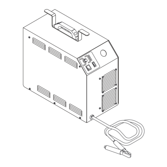
6.03 Major External Replacement Parts List Item # Description Catalog # Handle 9-8115 Bracket, Leads Wrap 9-7865 Cover, CutMaster 80XL Includes: 9-7866 For Units With PCH/M-76 Torch: 9-7866 Cover, CutMaster Label, PCH76 Torch Overlay, Side Panel, CutMaster Label, User Warning, French Label, User Warning, English For Units With PCH/M-102 Torch: 9-6692... - Page 49 A-02263 Note: Illustration may vary slightly from actual unit. Manual 0-2725 PARTS LISTS...
-
Page 50: Front Panel Replacement Parts List
6.04 Front Panel Replacement Parts List Item # Description Catalog # Base Front, CutMaster Includes: 9-7867 Base/Front, CutMaster Overlay, Front Panel, CutMaster Overlay, Control Panel, CutMaster USA Label (1-3/4 X 3) 8-3216 Ground Tag 8-4243 Contactor, 4 Pole, 40 FLA 120 VAC 9-7507 Strain Relief - .325-.360 Dia. - Page 51 A-02264 Note: Illustration may vary slightly from actual unit. Manual 0-2725 PARTS LISTS...
-
Page 52: Left Side Internal Component Replacement Parts List
6.05 Left Side Internal Component Replacement Parts List Item # Description Catalog # Insulator, Input PCB See Note Cable Assembly, 10 Cir Ribbon, 15" Lg 9-5922 Cable, 20 Circuit Ribbon 9-7510 Logic Control PCB Assembly 9-7631 Assembly, Gate Drive PCB 9-7562 Assembly, FET Heatsink Includes: 9-7633... - Page 53 To J10 On Logic PCB To Input A-02265 Note: Illustration may vary slightly from actual unit. Manual 0-2725 PARTS LISTS...
-
Page 54: Rear Panel Replacement Parts List
6.06 Rear Panel Replacement Parts List Item # Description Catalog # Pressure Switch-35 PSI 9-1044 Valve, Solenoid 1/8 NPT 8-3370 Regulator/Filter, Air Line 9-7514 Flex Connector 8-6307 1/4 NPT Street Elbow 9-2184 1/8 NPT Str. Tee 8-0352 1/4-1/8 NPT Reducer 9-2023 Fitting, 1/8 NPT X 2"... - Page 55 Part of #4 A-02535 Note: Illustration may vary slightly from actual unit. Manual 0-2725 PARTS LISTS...
-
Page 56: Right Side Internal Component Replacement Parts List
6.07 Right Side Internal Component Replacement Parts List Item # Description Catalog # Bulkhead Adapter, O2B - 1/8 NPT 9-4045 9/16-18 Jam Nut, Brass 8-2149 Heatsink, Input Rectifier See Note Center Chassis, CutMaster See Note Panel, Pilot Assembly Mounting See Note Bracket, Bulkhead Mounting See Note Insulator, Bulkhead... - Page 57 Used With PCH-102 Used With PCM-102 A-02244 Note: Illustration may vary slightly from actual unit. Manual 0-2725 6-11 PARTS LISTS...
-
Page 58: Options And Accessories
6.08 Options and Accessories Description Catalog # Two Stage Filter Kit (includes Hose & Mounting Screws) 7-7500 Bracket, Filter Mounting (not shown) 9-7535 Dual Stage Air Filter Assembly 9-7527 First Stage Cartridge 9-1021 Second Stage Cartridge 9-1022 Multi-Purpose Cart 7-8888 Torch Guide Kit 7-8910 First &... -
Page 59: Appendix 1: Input Wiring Requirements
APPENDIX 1: INPUT WIRING REQUIREMENTS In p u t P o w er In p u t C u r r en t S u g g ested S iz es (S ee N o te) V o ltag e F r eq . -
Page 60: Appendix 2: Sequence Of Operation (Block Diagram
APPENDIX 2: SEQUENCE OF OPERATION (BLOCK DIAGRAM) ACTION ACTION ACTION ACTION ON/OFF switch Close external RUN/SET RUN/SET switch to ON. disconnect switch. switch to RUN. to SET. RESULT RESULT RESULT RESULT AC indicator blinks for 8 Power to system. Gas flow stops. Gas solenoid open, seconds then steady on. -
Page 61: Appendix 3: Pot/Led Pc Board Layout
APPENDIX 3: POT/LED PC BOARD LAYOUT A-01206 Pot/LED PC Board Signals J14-1 +10 vdc from Logic PC Board (J3-7) J14-2 Current Control to Logic PC Board (J3-8) J14-3 Return for Current Control from Logic PC Board (J3-9) J14-4 +12 VDC from Logic PC Board (J3-10) J14-5 Signal for AC OK Indicator to Logic PC Board (J3-11) J14-6... -
Page 62: Appendix 4: Logic Pc Board Layout
APPENDIX 4: LOGIC PC BOARD LAYOUT Current Sensor A-01388 Logic PC Board Signals J1-1 36 VAC from Auxiliary Transformer J3-1 36 VAC to ON/OFF Switch J1-2 115 VAC from Auxiliary Transformer J3-2 36 VAC from ON/OFF Switch to Logic PC Board J1-3 Center Tap from Auxiliary Transformer J3-3... - Page 63 J4-1 36 VAC from Gate Driver PC Board (J9-1) J4-2 36 VAC to Gate Drive PC Board (J9-2) J4-3 36 VAC from Gate Drive PC Board (J9-3) J4-4 36 VAC to Gate Drive PC Board (J9-4) J4-5 Ground to Gate Drive PC Board (J9-5) J4-6 36 VAC to Gate Drive PC Board (J9-6) J4-7...
-
Page 64: Appendix 5: Gate Drive Pc Board Layout
APPENDIX 5: GATE DRIVE PC BOARD LAYOUT RESET TP11 TP12 POWER ENABLE TP13 A-01205 Gate Drive PC Board Signals J7-1 +12 VDC to FET PC Boards (J6-1) J7-2 Return for +12 VDC to FET PC Boards (J6-2) J7-3 PWM Output (A) to FET PC Boards (J6-3) J7-4 PWM Return to FET PC Boards (J6-4) J7-5... - Page 65 J9-1 36 VAC from Logic PC Board (J4-1) J9-2 36 VAC from Logic PC Board (J4-2) J9-3 36 VAC from Logic PC Board (J4-3) J9-4 36 VAC from Logic PC Board (J4-4) J9-5 Return from Logic PC Board (J4-5) J9-6 36 VAC from Logic PC Board (J4-6) J9-7 Return from Logic PC Board (J4-7)
-
Page 66: Appendix 6: Pilot Output Pc Board Layout
APPENDIX 6: PILOT OUTPUT PC BOARD LAYOUT CGND A-01389 Pilot Output PC Board Signals J12-1 Torch Switch Filter in from J22-3 Torch Control J12-2 Not Used J12-3 Torch Switch Filter Return from J22-4 Torch Control J12-4 Not Used J12-5 Pilot Return Shield to J22-1 Torch Control J12-6 Torch Switch Shield to J22-2 Torch Control J12-7... - Page 67 CGND Chassis Gnd PS(-) (Stud) from Output Inductor L1 to CD Xfmr PS(-) C4 Rtn for Pilot Voltage Twisted with Pilot RTN to E23 PS(+) to E18 Upper Fet Module PS(+) to E18 Upper Fet Module From E22 to PCR Pin 2 From Pilot Choke to E20 C4 Rtn for Pilot Voltage Twisted with Pilot RTN from E8 Pilot RTN from Standoff on bulk head and Torch Cable...
-
Page 68: Appendix 7: Cd Pc Board Layout
APPENDIX 7: CD PC BOARD LAYOUT J11-1 J11-3 J11-4 J11-5 A-01208 CD PC Board Signals J11-1 36 VAC from Logic PC Board (J5-1) J11-2 Return from Logic PC Board (J5-2) J11-3 36 VAC from Logic PC Board (J5-3) J11-4 CD Enable Signal from Logic PC Board (J5-4) J11-5 Return for CD Enable Signal from Logic PC Board (J5-5) J11-6... -
Page 69: Appendix 8: Input Pc Board Layout
APPENDIX 8: INPUT PC BOARD LAYOUT Component Side Of PC Board Solder Side Of PC Board A-01390 CGND Input PC Board Signals J16-1 Gate Drive Relay Rtn from Logic Board J10-1 J16-2 Gate Drive Relay Pos from Logic Board J10-2 J16-3 Not used J16-4... -
Page 70: Appendix 9: Fet Pc Board Layout
APPENDIX 9: FET PC BOARD LAYOUT Component Side Of PC Board XFMR SEC - OUTPUT MAIN XFMR PRI MAIN XFMR PRI MAIN XFMR SEC + OUTPUT FET PCB ASSY A-00479 Solder Side Of PC Board APPENDIX A-12 Manual 0-2725... - Page 71 FET PC Board Signals (Upper and Lower Assemblies) J6-1 +12V from the Gate Drive Board upper J7-1 Lower J8-1 J6-2 +12V RTN from the Gate Drive Board upper J7-2 Lower J8-2 J6-3 Pwm Output from the Gate Drive Board upper J7-3 Lower J8-3 J6-4 Pwn Output RTN J6-2 from the Gate Drive Board upper J7-4 Lower J8-4 J6-5...
-
Page 72: Appendix 10: Capacitor Pc Board Layout
APPENDIX 10: CAPACITOR PC BOARD LAYOUT E12A E12B E13A E13B A-00484 E13C E12C Capacitor PC Board Signals Positive Rail to FET Board E12A Positive Rail to FET Board E12B Positive Rail to FET Board E12C Positive Rail to FET Board Negative Rail to FET Board E13A Negative Rail to FET Board... -
Page 73: Appendix 11: 36Vac Circuit Diagram
APPENDIX 11: 36VAC CIRCUIT DIAGRAM CD PC Board Logic PC 12VDC Board Circuit 36 VAC Voltage Check Circuit Auxiliary (IN) 36 VAC Transformer Outputs (IN) 115 VAC Gate Drive PC Board J3 3 A-01344 ON/OFF Switch Manual 0-2725 A-15 APPENDIX... -
Page 74: Appendix 12: Maintenance Schedule
APPENDIX 12: MAINTENANCE SCHEDULE This schedule applies to all types of non-liquid cooled plasma cutting systems. Some systems will not have all the parts listed and those checks need not be performed. NOTE The actual frequency of maintenance may need to be adjusted according to the operating environment. Daily Operational Checks or Every Six Cutting Hours: Check torch consumable parts, replace if damaged or worn. - Page 75 Notes: Manual 0-2725 A-17 APPENDIX...
-
Page 76: Appendix 13: System Schematic
APPENDIX 13: SYSTEM SCHEMATIC A-02234 APPENDIX A-18 Manual 0-2725... - Page 77 11/23 EC 8055 12/18 EC 8087 ECO 39F6 09/15 ECO 3AF2 2001 A-02234 Manual 0-2725 A-19 APPENDIX...
Need help?
Do you have a question about the CE CutMaster 80XL and is the answer not in the manual?
Questions and answers