
Related Manuals for Thermal Dynamics CE CutMaster 80XL


Summary of Contents for Thermal Dynamics CE CutMaster 80XL
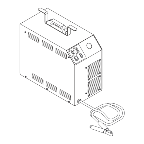
- Page 1 Plasma Cutting Power Supply ™ CE CutMaster 80XL A-02218 Operating Manual December 4, 2002 Manual No. 0-2724...
- Page 3 Manufacturer assumes no liability for its use. Plasma Cutting Power Supply CE Cut Master ™ 80XL Operating Manual Number 0-2724 Published by: Thermal Dynamics Corporation 82 Benning Street West Lebanon, New Hampshire, USA 03784 (603) 298-5711 www.thermal-dynamics.com Copyright 1998 by Thermal Dynamics Corporation All rights reserved.
-
Page 4: Table Of Contents
TABLE OF CONTENTS SECTION 1: GENERAL INFORMATION ....................1 1.01 Notes, Cautions and Warnings ................ 1 1.02 Important Safety Precautions ................1 1.03 Publications ..................... 2 1.04 Note, Attention et Avertissement ..............3 1.05 Precautions De Securite Importantes .............. 3 1.06 Documents De Reference ................ - Page 5 TABLE OF CONTENTS (continued) SECTION 6: PARTS LISTS ........................6-1 6.01 Introduction ....................6-1 6.02 Ordering Information ................... 6-1 6.03 Complete Power Supply Replacement ............6-2 6.04 Basic Parts Replacement ................6-2 6.05 Options and Accessories ................6-2 APPENDIX 1: INPUT WIRING REQUIREMENTS ..............A-1 APPENDIX 2: SEQUENCE OF OPERATION (BLOCK DIAGRAM) ..........
-
Page 7: General Information
SECTION 1: GASES AND FUMES GENERAL INFORMATION Gases and fumes produced during the plasma cutting process can be dangerous and hazardous to your health. 1.01 Notes, Cautions and Warnings • Keep all fumes and gases from the breathing area. Throughout this manual, notes, cautions, and warnings Keep your head out of the welding fume plume. -
Page 8: Publications
• Wear dry gloves and clothing. Insulate yourself from the work piece or other parts of the welding PLASMA ARC RAYS circuit. • Repair or replace all worn or damaged parts. Plasma Arc Rays can injure your eyes and burn your skin. •... -
Page 9: Note, Attention Et Avertissement
6. ANSI Standard Z49.2, FIRE PREVENTION IN THE USE ATTENTION OF CUTTING AND WELDING PROCESSES, obtain- able from American National Standards Institute, 1430 Broadway, New York, NY 10018 Toute procédure pouvant résulter l’endommagement du matériel en cas de non- 7. AWS Standard A6.0, WELDING AND CUTTING CON- respect de la procédure en question. - Page 10 • Eloignez toute fumée et gaz de votre zone de respira- • Ne touchez jamais une pièce “sous tension” ou “vive”; tion. Gardez votre tête hors de la plume de fumée portez des gants et des vêtements secs. Isolez-vous provenant du chalumeau. de la pièce de travail ou des autres parties du circuit de soudage.
-
Page 11: Documents De Reference
ultra-violets très forts. Ces rayons d’arc nuiront à vos 1.06 Documents De Reference yeux et brûleront votre peau si vous ne vous protégez pas correctement. Consultez les normes suivantes ou les révisions les plus récentes ayant été faites à celles-ci pour de plus amples •... - Page 12 9. Norme 70 de la NFPA, CODE ELECTRIQUE NA- TIONAL, disponible auprès de la National Fire Pro- tection Association, Batterymarch Park, Quincy, MA 02269 10. Norme 51B de la NFPA, LES PROCÉDÉS DE COUPE ET DE SOUDAGE, disponible auprès de la National Fire Protection Association, Batterymarch Park, Quincy, MA 02269 11.
-
Page 13: Declaration Of Conformity
Rigorous testing is incorporated into the manufacturing process to ensure the manufactured product meets or exceeds all design specifications. Thermal Dynamics has been manufacturing products for more than 30 years, and will continue to achieve excellence in our area of manufacture. -
Page 14: Statement Of Warranty
None Warranty repairs or replacement claims under this limited warranty must be submitted by an authorized Thermal Dynamics® repair facility within thirty (30) days of the repair. No transportation costs of any kind will be paid under this warranty. Transportation charges to send products to an authorized warranty repair facility shall be the responsibility of the customer. -
Page 15: Introduction
CutMaster rent Control 80XL Plasma Cutting Power Supply. Service of this equip- ment is restricted to Thermal Dynamics trained person- 2. Front Panel LED Indicators nel; unqualified personnel are strictly cautioned against attempting repairs or adjustments not covered in this AC, TEMP, GAS, DC manual, at the risk of voiding the Warranty. -
Page 16: Power Supply Options And Accessories
9. Weight 72 lbs (32.7 kg) 10. Overall Dimensions 18.9" (480 mm) High x 10" (254 mm) Wide x 23.5" (597 mm) Long Overall dimensions are with handle installed. B. Gas Regulator/Filter Assembly Specifications The following specifications apply to the Gas Regu- lator/Filter Assembly only: Maximum input gas pressure 125 psi (8.6 bar) -
Page 17: Installation Procedures
SECTION 3: CAUTION INSTALLATION Operation without proper air flow will inhibit PROCEDURES proper cooling and reduce duty cycle. 3.03 Unpacking 3.01 Introduction Equipment that was ordered as a system is packaged in one shipping carton. All options and the Torch are fac- This Section describes installation of the Power Supply tory installed. -
Page 18: Lifting Options
3.04 Lifting Options Mounting Screws WARNINGS Do not touch live electrical parts. Handle Disconnect input power conductors from de-ener- gized supply line before moving unit. FALLING EQUIPMENT can cause serious per- Leads Wrap sonal injury and equipment damage. HANDLE is not for mechanical lifting. This unit is equipped with one handle mounted on top of the enclosure for hand carrying purposes only. -
Page 19: Input Voltage Selection
Voltage Selection Connectors 460 Volts Cover 380-415 Volts 208/230 Volts A-02261 Cover Screws (5 Places On Each Side) Voltage Selection Voltage Selection Plug Label EMC Filter Figure 3-3 Input Voltage Selection A-02260 3.07 Input Power Cable Connections The Power Supply is supplied with a 460V three-phase input EMC power cable attached. -
Page 20: Gas Connections
3.08 Gas Connections A. Gas Requirements Regulator/Filter Assembly 1/4 NPT to #4 (6 mm) Hose WARNING Fitting This unit not to be used with oxygen (O Gases: Compressed Air or Nitrogen (N2) Only Hose Clamp Pressure: 60 psi (4.1 bar) CAUTION Maximum input gas pressure must not exceed 125 #4 (6 mm) Gas... -
Page 21: Connecting Torch Leads
5. Refer to the following when using high pressure A. Hand Systems gas cylinders as the gas supply: WARNING CAUTION Pressure should be set at 100 psi (6.9 bar) at the Disconnect primary power at the source before as- high pressure gas cylinder regulator. sembling or disassembling the power supply, torch parts, or torch and leads assemblies. - Page 22 Torch Leads Adapter Assembly Pilot Lead Stud Adapter Connector Strain Relief (Supplied With Power Supply) Control (PIP) Circuit Connectors A-02827 Negative/Plasma Lead Connection Strain Relief Pilot Lead Negative/Plasma Lead Figure 3-8 Strain Relief Nut Removal Torch Lead A-02825 Assembly 3. The Adapter supplied with the Power Supply must be installed as follows: Figure 3-7 Torch Lead Connections a.
- Page 23 4. Connect the torch Negative/Plasma Lead to the bulkhead connection inside the Power Supply. Torch Leads Assembly 5. Connect the Control (PIP) Circuit Connectors to Strain Relief the mating connectors on the Adapter supplied on the Power Supply (see Warning). WARNING A-02826 The Adapter supplied with the Power Supply has...
-
Page 24: Ground Connections For Mechanized Applications
5. Connect the PIP and Shield Cables to the mating 4. The plasma power supply work cable (see NOTE) is connectors on the Adapter supplied on the Power connected to the cutting table at the single point “Star” Supply. ground. 6. - Page 25 To test for a proper earth ground using 115 VAC, re- fer to the following diagram. Ideally, the reading on the multimeter should be 3.0 VAC or less. A-02971 Meter set to VAC setting WARNING VR COM Use extreme caution. This test uses live voltage.
- Page 26 INSTALLATION PROCEDURES 3-10 Manual 0-2724...
-
Page 27: Operation
3. Work Cable and Clamp SECTION 4: Work cable with clamp (factory Installed). OPERATION 4. Handle Handle used to lift and transport the power supply. 4.01 Introduction 5. Leads Wrap This Section provides a description of the Power Supply Bracket connected to the Cover of the unit for storing operating controls and procedures. - Page 28 5. TEMP Indicator D. Rear Panel Normally OFF. Yellow LED indicator will come ON 1. Gas Input when the internal temperature sensors detect tem- Input connection for nitrogen (N2) or air input. peratures above normal limits. The unit should be allowed to cool before continuing operation.
-
Page 29: Sequence Of Operation
6. Protect eyes and press or activate torch switch. a. Gas pre-flows starts. b. GAS indicator turns ON. 7. After gas pre-flow (approximately 2 seconds). a. Power supply enabled. b. DC indicator turns ON. c. Pilot relay closes. 8. Pilot arc is established. 9. -
Page 30: Preparations For Operating
E. Torch Connection 4.04 Preparations for Operating Check that the torch is properly connected. Follow this set-up procedure each time the system is op- erated: F. Purge the System (Gas Pre-Flow) Move the ON/OFF switch to ON position. To start the pre-flow move the RUN/SET switch to SET position for WARNING a minimum of 20 seconds. - Page 31 Kerf Width Description of Cut Characteristics The width of material removed during the cut. Excellent - Minimum bevel (0 - 4°), minimum kerf (2 x tip orifice diameter), little or no dross, smooth Nitride Build-up cut surface. Nitride deposits which may remain on the surface of the Good - Slight bevel (0 - 10°), slightly wider kerf (2-1/2 x cut when nitrogen is present in the plasma gas stream.
- Page 32 OPERATION Manual 0-2724...
-
Page 33: Customer/Operator Service
SECTION 5: 5.03 Common Operating Problems CUSTOMER/OPERATOR WARNINGS SERVICE Disconnect primary power at the source before dis- 5.01 Introduction assembling the power supply, torch, or torch leads. Frequently review the Important Safety Precau- This Section describes basic maintenance procedures per- tions (Section 1). -
Page 34: Troubleshooting Guide
Torch standoff too high from workpiece Cut Angle c. Worn torch parts d. Improper cutting current 3. Non-genuine Thermal Dynamics parts used. 4. Short Torch Parts Life A-00512 a. Oil or moisture in air source Figure 5-1 Side Characteristics Of Cut b. - Page 35 C. How to use this Guide 3. Unit is overheated a. Allow unit to cool down for about 5 minutes. The following information is a guide to help the Cus- Make sure the unit has not been operated be- tomer/Operator determine the most likely causes for yond duty cycle limit.
-
Page 36: Power Supply Parts Replacement
3. Poor input or output connections 5.05 Power Supply Parts Replacement a. Check all input and output connections. 4. Faulty components in unit a. Return for repair or have qualified technician WARNING repair per Service Manual. F. Erratic or improper cutting output Disconnect primary power to the system before dis- assembling the torch, leads, or power supply. - Page 37 C. Regulator/Filter Element Replacement The Regulator/Filter Assembly is on the rear panel. For Cover better system performance, the Regulator/Filter Assem- bly filter element should be checked per the Maintenance Schedule, and either cleaned or replaced. 1. Remove power from the power supply; turn off the gas supply and bleed down the system.
- Page 38 D. Optional Two-Stage Filter Element Replacement NOTES These instructions apply to any power supply with the optional Two-Stage Filter installed. The Two-Stage Air Filter has two Filter Elements. When the Filter Elements become dirty the Power Supply will continue to operate but cut quality may become unacceptable.
-
Page 39: Parts Lists
SECTION 6: PARTS LISTS 6.01 Introduction A. Parts List Breakdown The parts list provide a breakdown of all replaceable com- ponents. The parts lists are arranged as follows: Section 6.03 Complete Power Supply Replacement Section 6.04 Basic Replacement Parts Section 6.05 Options and Accessories NOTE Parts listed without item numbers are not shown, but may be ordered by the catalog number shown. -
Page 40: Complete Power Supply Replacement
6.03 Complete Power Supply Replacement Power supply includes: EMC Input Power Cable, Work cable, pressure regulator/filter, and operating manual. Description Catalog # CutMaster 80XL Power Supply (CE) 3-8800 6.04 Basic Parts Replacement Description Catalog # Fuse, 0.8A 600V 9-7526 Regulator/Filter Replacement Element 9-4414 6.05 Options and Accessories Description... -
Page 41: Appendix 1: Input Wiring Requirements
APPENDIX 1: INPUT WIRING REQUIREMENTS In p u t P o w er In p u t C u r r en t S u g g ested S iz es (S ee N o te) V o ltag e F r eq . -
Page 42: Appendix 2: Sequence Of Operation (Block Diagram
APPENDIX 2: SEQUENCE OF OPERATION (BLOCK DIAGRAM) ACTION ACTION ACTION ACTION ON/OFF switch Close external RUN/SET RUN/SET switch to ON. disconnect switch. switch to RUN. to SET. RESULT RESULT RESULT RESULT AC indicator blinks for 8 Power to system. Gas flow stops. Gas solenoid open, seconds then steady on. -
Page 43: Appendix 3: Maintenance Schedule
APPENDIX 3: MAINTENANCE SCHEDULE This schedule applies to all types of non-liquid cooled plasma cutting systems. Some systems will not have all the parts listed and those checks need not be performed. NOTE The actual frequency of maintenance may need to be adjusted according to the operating environment. Daily Operational Checks or Every Six Cutting Hours: Check torch consumable parts, replace if damaged or worn. -
Page 44: Appendix 4: System Schematic
APPENDIX 4: SYSTEM SCHEMATIC A-02234 APPENDIX Manual 0-2724... - Page 45 11/23 EC 8055 12/18 EC 8087 ECO 39F6 09/15 ECO 3AF2 2001 A-02234 Manual 0-2724 APPENDIX...
Need help?
Do you have a question about the CE CutMaster 80XL and is the answer not in the manual?
Questions and answers