Table of Contents
Advertisement
Advertisement
Table of Contents

Subscribe to Our Youtube Channel
Related Manuals for Focal Point versailles


Summary of Contents for Focal Point versailles
-
Page 3: Installation Instructions
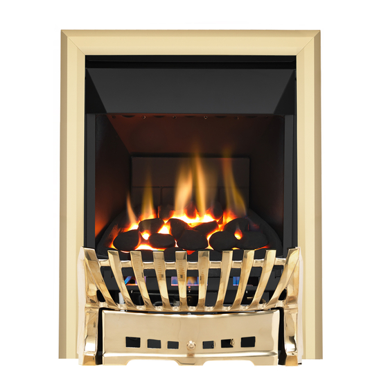
INSTALLATION INSTRUCTIONS Preliminary Notes Before Installation This appliance is an Inset Live Fuel Effect appliance which provides radiant and con- vected warmth utilising the latest type burner technology. The fire is designed to fit various types of fireplaces and natural flues as listed in the Installation Requirements. -
Page 4: Table Of Contents
Section Contents Page No. Section Contents Page No. Fitting the Burner Tray Important Notes Fuel Bed Layout Appliance Data 10.0 Fitting the Fireframe/Hood Installation Requirements 11.0 Testing and Commissioning Site Requirements 11.1 Operating the Appliance Debris Collection Space 11.2 Spark Failure Ventilation 11.3 Setting Pressure... -
Page 5: Appliance Data
This appliance is suitable for use with a "lightweight" surround and back panel of 150C minimum rating when installed with a 20 mm spacer frame available from Focal Point Fires plc. Part Number FB004210/0. -
Page 6: Site Requirements
SITE REQUIREMENTS The fireplace opening should be constructed of non combustable material. It should be inspected and repairs made where necessary. Any chair brick or fireback may be left in situ providing that the dimen- sional requirements for debris collection space and spigot clearances are met. The opening WIDTH and HEIGHT dimensions should be between 385 mm and 440 mm wide (365 mm with optional 20 mm spacer frame) and between 545 mm and 575 mm high. -
Page 7: Debris Collection Space
SITE REQUIREMENTS (continued) Any type of fire surround used with this appliance must be adequately sealed to the wall and floor. A combustible shelf may be fixed to the wall above the fire providing that is complies with the dimen- sions given below. -
Page 8: Unpacking The Appliance
PREFABRICATED FLUE BOXES This appliance can be fitted into a number of proprietary flue boxes provided that the minimum dimen- sions given in the diagram below are complied with. Constructional Note: The frame of the fire any back panel or other infill panels and the flue box must be sealed together so that there is no possibility of leakage between them. -
Page 9: Component Checklist
COMPONENT CHECKLIST QUANTITY DESCRIPTION Firebox and burner tray assembly Decorative frame - 3 piece Convection hood Cast front fret with separate ashpan door Moulded ceramic fibre combustion matrix Individual ceramic coals (5 moulded and 9 broken) Ceramic fibre side cheeks Ceramic brick panel Cable fixing kit;... -
Page 10: Gas Supply Routing
PREPARING THE OPENING (continued) and that the base is firm in the floor of the opening as no leaks are permissible here. At this stage it is essential to ensure that the spigot outlet of the fire is not obstructed in any way. Remove the convector box and take any necessary measurements before making good and preparing for final installation. -
Page 11: Fitting The Burner Tray
CABLE FIXING (continued) Thread the cable tensioners onto the cables as shown with the nuts screwed down close to the tensioner head. Slide the screwed nipple onto the cable, pull cable taut and tighten nipple. Adjust tensioner using a suitable spanner to pull the appliance back into position to allow an even seal around the fireplace opening. - Page 12 FUEL BED LAYOUT (continued) Place the ceramic combustion matrix onto the burn- er and the ceramic side cheeks onto the matrix. Place the front row of 5 moulded coals onto the matrix, equally spaced across the width of the fire. they may be at any rotational orientation desired.
-
Page 13: Fitting The Fireframe/Hood
FUEL BED LAYOUT (continued) This will reduce the possibility of heat discoloration. If the coals need adjustment to give a good flame picture allow the fire to cool, remove the glass door, rearrange to coals slightly, refit the door and check again. -
Page 14: Setting Pressure
11.3 SETTING PRESSURE Remove the screw from the pressure test point, which is situated on the main injector pipe and attach a U gauge. Light the fire on the HIGH setting. The setting pressure should be in accordance with the figures stated on page 2 of these instructions. The fire is factory set to achieve these pressures and any significant variation could indicate a supply problem. -
Page 15: Fitting The Firefront
12.1 TESTING FOR SPILLAGE (continued) All the smoke should be drawn away up the flue. Any smoke returning into the room indicates that spillage is occurring. If the initial spillage test fails, run the fire for a further 10 minutes and repeat the test. -
Page 16: Cleaning The Coals
15.0 SERVICING (continued) 5. Remove the cast front fret. 6. Remove the two screws that retain the data/control plate. 7. Disconnect the gas supply and remove the two securing screws in the tray legs. 8. Remove the burner tray. 9. Remove the convector box in reverse order of installation. 10. -
Page 17: Troubleshooting Guide
The fire box is now released from the opening and can be slid outward onto the hearth. Inspect the fireplace opening for debris and if excessive rectify the flue before proceeding further. Check the seal around the fireframe and if necessary replace. Refit the convector box as described in the fitting section of these instructions. -
Page 18: User Instructions
USER INSTRUCTIONS Section Contents Page No. Important Notes Firefront Clearances to Combustibles Ventilation Operating Instructions Flue Spillage Monitoring System Cleaning Coals and Ceramics Servicing IMPORTANT NOTES The installation and Servicing of this fire MUST only be carried out by a competent person (such as a CORGI registered fitter) in accordance with the Gas Safety (Installation and Use) Regulations 1998, the relevant British Standards, Codes of Practice, the Building Regulations and the manufacturer's instruc- tions. -
Page 19: Clearances To Combustibles
FIREFRONT This fire is supplied with a particular style of firefront. Use of the firefront will ensure an adequate air- flow under the firebed for the correct functioning of this appliance. Compliance with safety standards cannot be guaranteed another style of front is used. CLEARANCES TO COMBUSTIBLES A combustible shelf may be fixed to the wall above the fire, providing that it complies with the dimen- sions given below. -
Page 20: List Of Spare Parts
FLUE SPILLAGE MONITORING SYSTEM This fire is fitted with a flue spillage safety device (ODS). If the fire shuts down during use for no appar- ent reason then several reasons may be suspected. If a door or window has been opened creating a draught, then pilot disturbance could be the problem and removal of the draught should resolve this.
Need help?
Do you have a question about the versailles and is the answer not in the manual?
Questions and answers