Table of Contents
Advertisement
Quick Links
Advertisement
Table of Contents

Related Manuals for Qualstar 34XX Series


Summary of Contents for Qualstar 34XX Series
- Page 1 T h e T a p e E x p e r t s 34XX User’s Guide 500300 Rev. U...
- Page 2 However, no guarantee is given or implied that the document is error-free or that it is accurate with regard to any specification. Qualstar reserves the right to modify product designs and specifications without notice.
- Page 3 CAUTION References contained in this manual to DIP switch settings, jumper locations, primary voltages and other options are for reference only. Access to the interior of this equipment is restricted to dealers and qualified service technicians, and only in accordance with published service manuals and bulletins. WARNING PERSONAL INJURY MAY RESULT IF YOU DO NOT FULLY COMPLY WITH THE HANDLING, OPERATING, OR SERVICE INSTRUCTIONS FOUND IN A...
- Page 4 Bestimmungen eingeräumt. English Translation: This certifies that the Qualstar model 3402S, 3402SD, 3404S and 3404SD tape drives are RFI-suppressed in accordance with German Postal Regulation 1046/1984. The marketing and sale of this equipment was reported to the German Postal Service, along with the authorization to verify the above-mentioned models for compliance to the regulation.
- Page 5 Treat the merchandise carefully to assure its suitability for return. • Retain all shipping and packing materials. Returned merchandise must be shipped to Qualstar in the original packing material and carton. If the original packing material or carton has been damaged, a new set may be requested. •...
-
Page 6: Table Of Contents
Table of Contents 1. Tape Drive Installation....................1-1 Introduction ......................1-1 Model identification ....................1-1 Operating Environment....................1-1 Unpacking the Tape Drive ..................1-2 Tools required for Installation..................1-3 Power Requirements....................1-3 1.6.1 Power Connections.....................1-4 SCSI-2 Interface......................1-4 1.7.1 SCSI Bus Description..................1-6 1.7.2 SCSI Cables and Connectors ................1-8 1.7.3 SCSI Bus Termination ..................1-8 1.7.4... - Page 7 3.6.2 Density Modes....................3-10 Abnormal Conditions ....................3-12 3.7.1 The Tape Will Not Load...................3-12 3.7.2 An Out-Of -Tape-Stop Occurs................3-12 3.7.3 The Tape Comes Off the Supply Reel ..............3-12 3.7.4 A Power Failure Occurs...................3-13 3.7.5 A Tape Runaway Condition Occurs..............3-13 Aborting Online Operations from the Front Panel ..........3-14 4.
- Page 8 5.1.11 800 Mask WP .....................5-5 5.1.12 Block Length (Default = 2).................5-5 5.1.13 Buffer (Default = Normal)..................5-6 5.1.14 Busy (Default = Not Ready) ................5-6 5.1.15 Discon (Default = YES) ..................5-6 5.1.16 Early EOT (Default = Normal) ................5-6 5.1.17 EOM On Read (Default = No)................5-7 5.1.18 INQUIRY Data File ...................5-7 5.1.19...
- Page 9 General........................7-1 Error Messages ......................7-1 7.2.1 Non-Terminal Errors ..................7-1 7.2.2 Terminal Errors ....................7-1 7.2.3 Miscellaneous Messages ..................7-3 7.2.4 SCSI Error Messages ..................7-3 8. AC Power Configuration ....................8-1 Tools Required to Change AC Power Configuration ..........8-2 Configuring the Drive for Available Power..............8-2 viii 500300 Rev.
-
Page 10: Tape Drive Installation
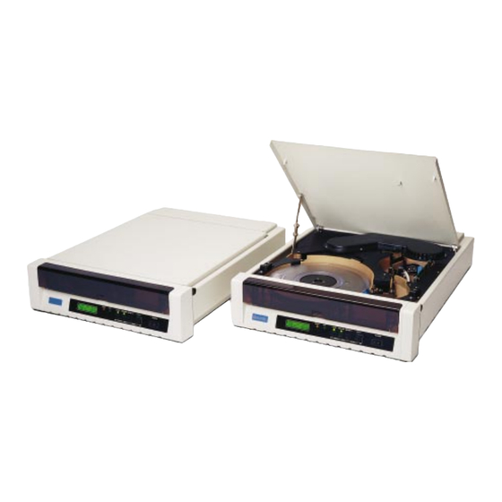
Introduction This guide provides installation instructions and techniques for operating the Qualstar Model 34XX Series tape drive. Figure 1-1 The Qualstar 34XX Series Tape Drive Model identification Figure 1-2 identifies the various 34XX models. This User's Guide applies to all models;... -
Page 11: Unpacking The Tape Drive
Basic Series See Table Below Interface Options Blank = Industry Standard Interface S = SCSI-2 Single-Ended SD = SCSI-2 Differential (HVD) 3 4 X X X X – X X Special Features Configuration Supported Densities Rack Mount Desktop 1600 3200 6250 6250 125 IPS... -
Page 12: Tools Required For Installation
from the carton and store the end-caps and bag in the carton. Store the carton for possible future transportation. Tools required for Installation A #2 Phillips screwdriver may be required to install the drive. Power Requirements The tape drive requires 100, 120, 220, or 240 volts AC, +10%/-15%, at 48 to 62 Hertz primary power. -
Page 13: Power Connections
1.6.1 Power Connections The power connection to the drive is by means of a detachable power cord that complies with the following specifications. There should be a minimum of 1.7-inches clearance from the rear of the drive for the power connector. •... - Page 14 TAPE DRIVE INTERFACE CONNECTORS SCSI CONNECTOR SCSI TERMINATORS WREX CONNECTOR SCSI CTLR RESET EPROM FUSE POWER VTERM CONNECTOR PCBA 500567- 250V PCB500566-01-3 REV B SCSI TERMINATION POWER Figure 1-4 SCSI Single-Ended PCBA Layout – 500567 PCBA CAUTION The single-ended and differential interfaces are electrically different. A device with a differential SCSI interface will not operate if connected to a single-ended SCSI bus.
-
Page 15: Scsi Bus Description
PCBA 5000467- Figure 1-5 SCSI Differential Adapter PCBA 1.7.1 SCSI Bus Description A SCSI system consists of two or more devices connected together by a multi-line cable, commonly referred to as the SCSI bus. SCSI Devices (locations on cable are Multiple SCSI Cables independent of SCSI ID assignments) An external terminator may... - Page 16 • The bus must have at least two devices connected to it; • The device addresses (SCSI ID) range from 0 through 7; • A device's priority on the bus is determined by its address, with SCSI ID 7 being the highest priority;...
-
Page 17: Scsi Cables And Connectors
1.7.2 SCSI Cables and Connectors Two identical drive connectors, wired in parallel at the rear of the drive, provide a connection point to the SCSI bus. Because both drive connectors are wired in parallel, you may use either one as an input or output, or for an external SCSI bus terminator. - Page 18 SCSI port on the tape drive. You may purchase active terminators from Qualstar. Figure 1-8 Connecting the SCSI Cable to the Tape Drive (SCSI Alternative 2 shown) Tape Drive Installation 500300 Rev.
-
Page 19: Termination Power
VTERM is installed, the device's +5 volt supply draws current from the Qualstar drive via the SCSI bus TERMPWR line. If the current draw becomes excessive, the circuit protector on the Qualstar SCSI PCBA opens, removing the termination voltage from the SCSI bus. -
Page 20: Industry Standard Interface (Non-Scsi)
remove VTERM, or always turn the tape drive off before turning the system off, and always turn the tape drive on after applying power to the system. Be sure that the tape drive is never turned on when the system is off. 1.7.5 Industry Standard Interface (non-SCSI) The computer interface will consist of either two cables with a 50-pin card edge... -
Page 21: Rack Mount Installation
The upper cable entry cover must be installed to insure proper cooling. If the installation is in question, please call Qualstar. All drives ship with rubber feet on the bottom. To prevent possible cabinet interference when rack-mounting the drive, these rubber feet should be removed. - Page 22 Separate the inner and outer slides of the remaining assembly and attach the rails to the drive and to the rack. Figure 1-12 shows the mounting locations for attaching the slides to the drive. Attach a rack latch to the standoffs provided inside of right side of the bezel as shown in Figure 1-13.
- Page 23 Right Cabinet Right Cabinet Mounting Rail Mounting Rail Inside upper Right Corner of Drive Bezel Standoffs Figure 1-13 Location of Rack Latch 1-14 Tape Drive Installation 500300 Rev. U...
-
Page 24: Controls And Indicators
Controls and Indicators BUSY LOAD ONLINE DENSITY MENU POWER ENTER EXIT Figure 2-1 Front Control Panels Front Control Panels 2.1.1 Power Switch The power switch applies power to the drive. Press the left side ( ) to turn the drive on;... -
Page 25: Front Panel Indicators
Pressing ONLINE while the tape is loading will toggle the pending online state. A message indicates the drive will not go online at the completion of the load LOADING sequence; an message indicates the drive will automatically go online ONLINE PEND after the load sequence is complete. -
Page 26: Liquid Crystal Display
• LOAD - The tape is loaded and positioned at loadpoint (BOT). • ONLINE - The tape is loaded and the drive is online and ready to accept a command. • MENU - The drive is in the menu mode, as opposed to the operating mode. You use the menu mode to select drive options and operating parameters, and to perform diagnostic tests. -
Page 27: Display Line One
(A) DURING POWER- UP: MODEL 3412S Display Line One SELF-TEST NO. 19 Display Line Two (B) TAPE UNLOADED: 6250sSTANDBY #0 Initial Density Drive Address (blank if SCSI Drive) S = Indicates Slow Status GCR (62.5 ips) (C) DRIVE OFFLINE: 6250sOFFLINE Display Line Two Status (D) TAPE DRIVE ONLINE... -
Page 28: Display Line Two
different densities. When the density indicator shows 6250, a small letter to the right of the density indicates “slow-GCR”—GCR at 62.5 IPS. 2.3.1.2 Status • STANDBY - Indicates the tape is not loaded. • OFFLINE - Tape is loaded but the drive is offline and unable to accept a host command. - Page 29 Display line two continues to indicate the read and detected densities when the drive is placed online. When the tape moves forward from BOT, display line two becomes a message line and its density indicators will be erased. 2.3.2.2 Messages The message line is used to display general information, instructions, error conditions, and other data depending upon the current situation.
-
Page 30: Operating Instructions
Operating Instructions Applying Power Before plugging in the tape drive, switch the power switch to the OFF position as shown in Figure 3-1. Figure 3-1 Power Switch Location Observe the label on the rear panel to verify the drive is already configured for the available AC voltage. -
Page 31: Power-Up Self Diagnostic Tests
Applying power initiates the following sequence: The drive starts the internal blower. Display line one indicates the drive model number. The drive then performs a series of self-tests. As each test is performed, display line two indicates where is the number of the test. SELF-TEST NO. -
Page 32: Loading A Tape
Test # Test # Test Name Comments (341X) (340X) +5 V Check the +5 volt supply ±15 V Check both the +15 and -15 volt supplies ±6 V Check both the +6 and -6 volt supplies +22 V (Line Voltage) Check the +22 volt supply;... - Page 33 Figure 3-3 Dust Protector and Write-enable Ring Open the front door by pulling it toward you as shown in Figure 3-4. Figure 3-4 Opening the Door Insert the tape reel with the label side up (write-enable ring down) through the door and onto the supply hub.
-
Page 34: Load Sequence
Figure 3-5 Correct Way to Insert Reel Close the door. Press the LOAD switch. 3.3.1 Load Sequence Pressing the LOAD switch when the door and the top cover are closed initiates the following load sequence: Display line one will indicate while the drive threads and DDDD LOADING tensions the tape. -
Page 35: Aborting A Load Sequence
3.3.2 Aborting a Load Sequence You may cancel the load sequence by pressing LOAD before the THREADING TAPE message appears. The drive will stop the load process, display CANCELING LOAD . ., wind the tape back on the supply reel and unlock the hub. Display line 2 will then indicate whereupon the tape may be removed. -
Page 36: Tape At Bot
Figure 3-7 Correct Method of Removing Tape Reel 3.4.2 Tape at BOT If the tape is at BOT (LOAD indicator illuminated), pressing LOAD will cause the drive to display . If you release the LOAD switch immediately, HOLD FOR UNLOAD nothing happens. -
Page 37: Automatic Density Selection Feature (Ads)
• You can change the density by pressing the Density switch on the front panel when the drive is in the standby condition or when it is offline and the tape is at BOT. The Density switch is disabled when the drive is online. •... - Page 38 Normally, the tape drive determines the read density by reading the ID burst on the tape. The read density is indicated at the beginning of display line two while the tape is at BOT as shown in Figure 3-6. After the tape has left BOT, the read density is no longer displayed.
-
Page 39: Density Modes
• The tape was recorded using an older DPE format (3200 CPI) that does not have an ID burst. If a tape with no ID burst is loaded, the detected density indicator in display line two will contain the value of NO-ID DEN followed by an asterisk ( * ). If NO-ID DEN is set to and you load a tape with no ID burst, the detected density BLANK... - Page 40 In this mode, you can change the write and read densities by the Density switch, the interface, or by loading a tape of a different density. 3.6.2.3 Read Mode In the Read mode, the drive reads the ID burst at the end of each load sequence and changes the read density to match it.
-
Page 41: Abnormal Conditions
• The drive performs all write commands from BOT at the indicated write density and changes the operating density to match. In this mode, you can change the write density by the Density switch, the interface, or by changing the value of the INITIAL DENS parameter and then loading a tape. Abnormal Conditions 3.7.1 The Tape Will Not Load... -
Page 42: A Power Failure Occurs
Raise the top cover by lifting it up at its front corners just behind the bezel as shown in Figure 3-11. Figure 3-11 Raising the Top Cover When fully open, the cover latch will hold it up. You may have to extend the drive further out from the rack. -
Page 43: Aborting Online Operations From The Front Panel
3.7.5.1 Terminating Runaways Via the Host One method of recovering from a tape runaway in non-SCSI drives is via the Formatter Enable interface line (IFEN), or via a Bus Reset if using the SCSI configuration. This is the recommended method, and is described in Product Specifications 500240 (341X), 500540 (340X), and 500358 (SCSI Interface Manual). - Page 44 • VARIABLE LENGTH ERASE - The drive will terminate the erase operation and go offline. Normally, the host determines the erase length. The drive will resume normal operation when placed back online. Operating Instructions 3-15 500300 Rev. U...
-
Page 45: Menu Operations
Menu Operations Menu System Description The menu system replaces the conventional internal switches and jumpers required to configure a drive to a particular application. It also provides a means of calibrating the drive and performing certain diagnostic tests. C.E. RESET HEAD MAINTENANCE DRIVE SCSI... -
Page 46: Accessing The Menu Mode
4.1.2 Accessing the Menu Mode You can access the Menu mode by pressing the MENU switch whenever the drive is in the standby state (i.e., whenever the drive is offline and not rewinding, loading or unloading). The MENU indicator will illuminate when the drive is in the Menu mode. -
Page 47: Drive Configuration Menu
equivalent 2400-foot reels run from BOT to EOT and back (i.e., 4800 feet). If the total footage exceeds the amount set in the HEAD CLEAN parameter of the Drive Configuration menu (also expressed in 2400-foot reels), the message TAPE UNLOADED will be replaced by a message when you open the door or press a TIME2CLEAN HEAD... - Page 48 ALL, 2TK, (NONE) Correctable error reporting to host (341X only) HER ON BLANK: YES, (NO) Reports IHER when blank tape detected EMULATION: (QUALSTAR), CIPHER Defines IDBY for invalid commands. READ ONLY: (NO), YES Disables write and erase functions FMK GAPS: (NORMAL), SHORT Short = 0.6-inch (0.3-inch in GCR)
-
Page 49: Drive Configuration Menu Parameters
DN UP SAVE ABORT INITIAL DEN:1600 Display line one now describes the alternate functions of the four push-button switches (in order from left to right). • Pressing the ( ) or ( ) switches scrolls through the list of available selections in opposite directions. - Page 50 EOT, the tape will eventually come off the supply reel and the drive will display MOTION FAULT Qualstar recommends you enable this feature by setting it to , as this still allows the drive to read and write up to thirteen feet past the EOT marker without danger of the tape coming off of the supply reel.
- Page 51 • - The drive will not report a hard error when it detects blank tape. 4.3.2.8 EMULATION: (Default = Qualstar) This parameter defines IDBY when an invalid command is received, or when an unsupported density is requested, or when a write command is received while the drive is file protected.
- Page 52 This option allows the 34XX Series to function with those controllers that do not support IFEN.
- Page 53 opportunity for tape streaming, and increasing the throughput in systems that otherwise might not be able to keep up with the drive. If the system presents the next command to the drive before the extended gap has been fully traversed, the drive will truncate the unused portion of the extended gap and use only the minimum necessary to maintain streaming.
- Page 54 Sometimes poorly–maintained equipment was used, which produced low–quality tapes. Reading Seismic tapes today, three decades after they were recorded, presents a special challenge to any tape drive. Therefore, Qualstar developed the SEISMIC option for reading difficult–to–read 800 CPI tapes.
- Page 55 ON. Using the SEISMIC option will not harm the drive or the tape. The SEISMIC option affects Qualstar Model 3410/12 and 3416/18 tape drives. It only affects the reading of 800 CPI (NRZI) tapes. When activated, the feature eliminates the reporting of Hard Errors (HERs) caused by the CRCC and LRCC characters found at the end of each NRZI data block.
-
Page 56: Manual Threading Function
marginal read signal amplitudes. This option is not available on model 340X tape drives. • - Enables the adaptive PE automatic gain system AUTO • - Selects a fixed value of PE read gain. FIXED 4.3.2.23 GCR SPEED: (Default = Norm) This parameter is present in all 341X drives, but is only functional in models 3416 and 3418. - Page 57 MAINTENANCE SUB-MENU COMMENTS SUB-MENUS FUNCTIONS DEFAULT CONFIG. Resets Drive Configuration parameters to defaults DEF. SCSI CONFIG. Resets SCSI Configuration parameters to defaults SCSI ENABLE: Enable/disable communications to SCSI PCBA DISPLAY MODEL NUMBER Displays the tape drive model number FIRMWARE SERIAL NUMBER Displays the tape drive serial number EXEC.
-
Page 58: Using The Maintenance Menu
Table 4-3 Maintenance Sub-Menus and Functions 4.5.1 Using the Maintenance Menu To enter the Maintenance menu: Place the drive offline. Press the MENU switch; the MENU indicator should illuminate. Press until display line one indicates MAINTENANCE Press ENTER. Display line one indicates DEFAULT CONFIG To select this function, press ENTER (see Note 1 at the bottom of Table 4-3. -
Page 59: Display Firmware Sub-Menu
• - The SCSI interface is not in use. Pressing ENTER a second time toggles this function between . Pressing EXIT leaves the function as indicated in the display. indicates NO SCSI RESPONSE that the SCSI PCBA is not connected or that it is being held reset by the SCSI bus. 4.5.5 Display Firmware Sub-Menu sub-menu displays internal information about the drive and... - Page 60 4.5.6.1 Write Ident Function functions allow you to initialize a blank tape (or to WRITE 6250 (3200, 1600) IDENT reinitialize prerecorded tapes) to a recording density of his choice. These functions will write the selected ID burst, erase 50 feet of tape, and rewind the tape back to BOT.
-
Page 61: Demonstration Function
4.5.7 Demonstration Function function is a sales tool mode that exercises tape motion and DEMONSTRATION displays a series of messages describing the features of the drive. It may be stopped by pressing or EXIT. 4.5.8 Diagnostics Sub-Menu The Diagnostics sub-menu contains several offline functions that can assist you in isolating suspected problems with the tape drive. - Page 62 If the tape drive is unable to write an error-free block within five write retries, will be displayed and the test will be terminated; WRITE FAIL The drive writes two filemarks and rewinds the tape; The drive reads the tape in the streaming mode from BOT to the first filemark, checking each block for the following conditions: Hard data errors Block length errors...
- Page 63 If unrecoverable errors are detected, they will be reported in display line two and the test will halt. Note the message and then press any switch to resume the test. Report the exact text of any error messages to a service representative.
- Page 64 Press ENTER. The BUSY indicator illuminates and the tape moves forward. Display line two indicates , and display line one provides a tape BOT/EOT TEST progress indicator and also shows the reel size. If the EOT sensor is functioning, the test rewinds the tape and checks the BOT sensor upon completion.
- Page 65 An “ ” appearing in display line one indicates that the command was received before the tape drive reinstruct window closed, allowing the tape to stream. Loading a tape clears the command log. On SCSI models, this function does not display the commands that were transferred via the SCSI bus, but displays the commands that were transferred from the SCSI PCBA to the WREX PCBA.
-
Page 66: Service Sub-Menu
visible. If no segments are visible, the line voltage is low but still okay; if all sixteen segments are visible, the line voltage is high but should be checked. If the message appears on the liquid crystal display, the line voltage LOW LINE VOLTS is unacceptably low. - Page 67 Apply power to the tape drive. The power up diagnostics will display a checksum error message on the front panel display for each EPROM that was changed. Press any switch each time this occurs to continue the diagnostics. When the diagnostics are complete, the display will indicate STANDBY.
- Page 68 • It displays the part number of the Read Formatter PCBA installed in 341X drives. • It asks you whether the SCSI PCBA should be enabled. • It resets all SCSI configuration parameters to their factory default values. Moving W1 on the WREX PCBA from ON to OFF disables this function and causes the display to read FEATURE LOCKED.
- Page 69 After about two minutes, the drive will request a 10.5-inch reel of tape with a write-enable ring installed. Insert a full 10.5-inch reel (2400-foot), close the door, and press LOAD to continue the calibration. Do not use a valuable tape for this procedure.
-
Page 70: Scsi Configuration
SCSI Configuration SCSI Configuration Menu Qualstar SCSI-2 drives have an additional menu called the SCSI Configuration menu that allows you to define the parameters shown in Table 5-1. A detailed description follows the table. LCD DISPLAY SELECTABLE VALUES COMMENTS (PARAMETER) -
Page 71: Scsi Device Id (Default = 5)
5.1.1 SCSI Device ID (Default = 5) This parameter allows you to define a SCSI Device ID from 0 to 7. The SCSI ID is independent of the drive's physical location on the SCSI bus, and depends upon the desired priority for the drive in the system. SCSI ID 0 is the lowest priority, and SCSI ID 7 is the highest. -
Page 72: Unload (Default = Normal)
where there is no read-ahead operation. If the drive receives a Space Blocks command when it is in the Write mode, two courses of action are possible: • - After spacing across the specified number of blocks, the drive READ AHEAD switches to the Read mode and continues to move tape and read blocks into the buffer until the buffer is full (i.e., perform a read-ahead operation.) This is advantageous if the next command is a Read or Read Reverse command,... -
Page 73: Write Eot (Default = Write)
• - If the final retry was successful, the drive reports a Recoverable Error. RETRY If it resulted in a CER or HER, the drive reports a Media Error. • - If the final retry was successful or resulted in a CER, the drive reports a Recoverable Error. -
Page 74: Write Retrys (Default = 13)
5.1.10 Write Retrys (Default = 13) The Write Retries parameter lets you set the number of automatic retries the drive will perform when it detects a hard or correctable error during a write operation. For each retry, the drive will backspace the tape over the block, erase a four-inch length of tape, and then rewrite the data. -
Page 75: Buffer (Default = Normal)
received after this parameter has been changed, the value in that Mode Select command takes precedent. Setting a value of 0 sets the default to the variable block mode. 5.1.13 Buffer (Default = Normal) The Buffer parameter refers to the use of the one-megabyte buffer. •... -
Page 76: Eom On Read (Default = No)
INQUIRY command. The following choices are available: • - The standard data file that reflects a Qualstar 34XX tape drive; QUALSTAR • Various others - These data files look like those returned by other vendors' tape drives as shown in Table 5-3. - Page 77 0-STD-03-46M990- 64K1 M995 018002021F000010 CIPHER M995 1.36 M996 018002021F000010 CIPHER M996 1.36 NCR ADP 01C5000027C10701 NCR ADP- QUAL STAR SCSI 07.021054 Qualstar 018002021F000010 QUALSTAR 3402/4S 1.36 340XS Qualstar 018002021F000010 QUALSTAR 3402/4SD 1.36 340XSD Qualstar 018002021F000010 QUALSTAR _3410 1.36 341X 018002021F000010 4280 1.36...
- Page 78 You can connect your tape drive to a variety of hosts by editing the CUSTOM data file. Its four fields make up the SCSI Inquiry data file, described in detail in Qualstar document 500358, SCSI Supplement, 34XX Series: • Custom Bytes 0-7 - These eight bytes of hexadecimal data are bytes 0 through 7 of the Inquiry data file.
-
Page 79: Lng Blk (Default = Stop)
to change the value of the underlined digit; Use ENTER to save the value above the cursor and to advance the cursor one place to the right; To accept the data as displayed and leave the editing mode, press EXIT; to select the next field to be edited;... -
Page 80: Nrzi (Default = No Lrc/Crc)
and is not changed by the DEF SCSI CONFIG. function in the Maintenance menu. Depending upon the value set in this parameter, the tape drive will accept the following density changes from the host: VALUE VALID DENSITIES 3402/4 1600, 3200 3410/2 800, 1600, 3200, 6250 3413/4... -
Page 81: Read Cer (Default = Ignore)
Read, Read Reverse, or Space Blocks command. This is most noticeable when the host sends a command to read one block while the tape is at BOT, or to read one block in the opposite direction (i.e., read reverse after a read forward operation). If read-ahead is enabled, the drive will continue to move the tape and read blocks into the buffer until the buffer is full. -
Page 82: Residue (Default = Normal)
REQUEST SENSE command. These bytes are also known as the residue count, and their value equals the requested block length minus the actual block length. Qualstar SCSI-2 drives feature an enhancement that allows you to redefine the residue count. •... -
Page 83: Special Drive Configuration Menu Requirements For Scsi Drives
• - Forces the tape drive to automatically perform retries when it detects a corrected error while writing. The number of retries is determined by the Write Retrys parameter described in Section 5.1.10. • - Prevents the tape drive from automatically performing retries when it detects a corrected error while writing. -
Page 84: Wrt Parity
5.2.7 WRT Parity The WRT Parity parameter must be set to (Internal) for proper drive operation. SCSI Error Messages and Codes As part of the power-on sequence, the SCSI PCBA performs diagnostics on itself to verify proper operation. If it detects a failure during these power up diagnostics, it will display one of the error messages in Table 5-4. -
Page 85: Preventative Maintenance
Preventative Maintenance The only preventive maintenance you need to do on your tape drive is keep the head and tape path clean. To remind you to clean the head and tape path components, the front panel display will indicate each time a predetermined TIME2 CLEAN HEAD amount of tape has passed the head. -
Page 86: Tape Path Cleaning Procedure
workbenches will accumulate dust on the reel flanges that will eventually work its way into the tape path. Tape which has been partially unwound onto the floor or which has picked up fingerprints will transfer the dust and oil from the fingerprints to the tape cleaner and guides, necessitating more frequent cleaning. - Page 87 Figure 6-1 Tape Path Components That Must Be Cleaned Figure 6-2 Cleaning the Read/Write Head Figure 6-3 Cleaning the Tape Guides Clean the tape cleaner blade as shown in Figure 6-4. Preventative Maintenance 500300 Rev. U...
-
Page 88: Using 1-Mil Tape
TexPads are individually sealed pads pre-moistened with 91% isopropyl alcohol and ® are ideal for head and tape path cleaning. You can order them from Qualstar, or directly from The Texwipe Company by calling (800) 284-5577. Using 1-mil Tape 1-mil tape was originally designed for low-speed data logging applications. Due to their thinner Mylar substrate, they do not meet the ANSI specifications for thickness;... -
Page 89: Data Specifications
(This is true for all reel-to-reel tape drives.) If more than 10% of the tapes used are 1-mil tapes, Qualstar recommends you dedicate one particular tape drive to the use of thinner tapes. -
Page 90: Media Requirements
6.5.3 Media Requirements The drive operates reliably using any tape meeting the requirements of ANSI X3.40- 1983 and certified for 6250 CPI. Defective tapes and tapes that have been damaged or subjected to heavy wear may not load or pack properly and should not be used. Tapes frequently wear out near the beginning of tape (BOT) tab as this is the area of greatest use. -
Page 91: Data Capacity Tables
Erased Areas on the Tape - The more erased areas a tape contains, the less data it can hold. 6.6.1 Data Capacity Tables The following tables, showing the data capacities in megabytes for various length tapes, assume a constant block length, no filemarks, and standard gap lengths. NOTE While all 34XX tape drives are capable of reading or writing data blocks of any length, not all computers are equally capable. - Page 92 1024 15.3 30.5 45.8 2048 11.5 22.9 45.0 68.8 4096 15.3 30.6 61.2 91.9 8192 18.4 36.8 73.6 110.4 16384 10.2 20.5 40.9 81.8 122.8 32768 10.8 21.7 43.3 86.7 130.0 Table 6-3 Formatted Tape Capacities, 3200 CPI Preventative Maintenance 500300 Rev.
- Page 93 Length (ft): 1200 2400 3600 Block Size MEGABYTES 12.6 16.0 24.0 14.7 29.4 44.2 1024 12.4 25.3 50.6 75.9 2048 10.1 20.2 39.5 79.0 118.5 4096 13.9 27.9 54.9 109.8 164.7 8192 17.2 34.5 68.2 136.4 204.6 16384 19.5 39.0 77.6 155.2 232.8...
-
Page 94: Errors And Operational Failures
Errors and Operational Failures General Your tape drive continually monitors certain critical areas for proper operation. If it detects a malfunction or exception condition, it will display an appropriate error message, error code, or both. These error messages tell you the nature of the malfunction, and are grouped into two general categories: •... - Page 95 10 to 100. The drive will also display in display line two. CMD:YY STATUS:ZZ represent hexadecimal code numbers for internal Qualstar use. Motion faults are described in Table 7-7 and Table 7-8. 7.2.2.4 Position Faults Position faults are detected during read or write operations from BOT. Errors associated with the reading and writing of data blocks are not considered position faults.
-
Page 96: Miscellaneous Messages
7.2.3 Miscellaneous Messages Depending upon the circumstances, you may be required to intervene before tape drive operation can continue. In these cases, a two-line message will be displayed on the front panel. These messages are described in Table 7-4. 7.2.4 SCSI Error Messages SCSI drives may report additional error messages not documented in this chapter. - Page 97 ERROR DISPLAY DEFINITION NOT SELECTED Drive address not set to 0 and SCSI operation is enabled. OUT OF TAPE STOP The tape has reached a point 13 feet beyond the EOT marker strip.1 RD-LDP, ARA 2LONG The ARA burst exceeded 15-inches while reading a GCR tape from loadpoint. RD-LDP, BOT HUNG The tape drive continually senses BOT during a read operation from loadpoint.
- Page 98 ERROR DISPLAY MEANING BAD INTERRUPT XX An illegal CPU interrupt on the Write/Executive board has occurred, where XX = a vector number between 1 and 17. This most likely indicates a firmware problem. FAN FAILURE The fan has not started. GO FWD FAULT: XX An error associated with tape position during ramp-up has occurred.
- Page 99 ERROR DISPLAY MEANING ERROR DISPLAY MEANING LOAD FAULT: 10 The Arm Index signal is LOAD FAULT: 28 Supply reel not turning TENSION ARM PROB present at the start of the freely. load cycle. LOAD FAULT: 11 The supply reel is LOAD FAULT: 29 Supply reel not turning REEL DRAGGING?
- Page 100 Table 7-5 Load Errors Errors and Operational Failures 500300 Rev. U...
- Page 101 ERROR DISPLAY MEANING UNLOAD FAULT: 49 Can't pull tape out of path. Possible TIP1 or TIP2 sensor failure. UNLOAD FAULT: 50 Supply reel will not stop turning. UNLOAD FAULT: 51 No File Protect/Reel-In-Place signal. Possible FPT sensor failure. REEL DRAGGING? UNLOAD FAULT: 52 No File Protect/Reel-In-Place signal.
- Page 102 MOTION FAULT MEANING Motion CPU failed to become ready after power up. A time-out occurred on a new command to the Motion board. A time-out occurred during the Receive Motion Byte routine. 33-37 Error occurred during data transmission between WREX and Motion boards. Tape loading failure (handled separately).
- Page 103 MOTION FAULT MEANING The tachometer sensor has failed. The tension arm sensor has failed. The tension arm index sensor has failed. The BOT sensor has failed. The EOT sensor has failed. The TIP1 sensor (nearest the supply hub) has failed. The TIP2 sensor (nearest the take up hub) has failed.
- Page 104 ERROR MESSAGE MEANING AND POSSIBLE CAUSES BLOWER POWER Something is causing the blower to draw too much current. Check for EXCESSIVE binding. TAPE-IN-PATH #1 This problem could be caused by defective sensors or associated wiring, or SENSOR PROBLEM by defective infrared emitters in the sensors. TIP1 and TIP2 emitters are wired in series and if one emitter is open, the other sensor will not function.
-
Page 105: Ac Power Configuration
AC Power Configuration DANGER THE PROCEDURES IN THIS CHAPTER INVOLVE A POTENTIAL SHOCK HAZARD AND SHOULD ONLY BE CARRIED OUT BY QUALIFIED SERVICE PERSONNEL. HAZARDOUS VOLTAGES ARE PRESENT WHEN THE REAR COVER IS REMOVED. DISCONNECT THE AC LINE CORD BEFORE REMOVING THE REAR COVER. GEFAHR DIE IN DIESEM KAPITEL BESCHRIEBENEN VERFAHRENSWEISEN BESITZEN EINE POTENTIELLE SCHOCKGEFAHR UND SOLLTEN DESHALB NUR VON... -
Page 106: Tools Required To Change Ac Power Configuration
Tools Required to Change AC Power Configuration • #2 Phillips screwdriver Configuring the Drive for Available Power LINE VOLTAGE AT CORRECT POWER CONNECTOR SWITCH SETTINGS 85 to 110 VAC 102 to 132 VAC 187 to 242 VAC 204 to 264 VAC Table 8-1 AC Power Configuration Switches To configure rack mount tape drives to a particular line voltage: Remove the power cord from the rear of the drive. - Page 107 Attach the power cord to the power receptacle only after confirming that the line voltage is correct and that the power switch is turned off. Switches shown Set for 120 VAC LINE VOLTAG E 100V CAUTION: REMOVE POWER BEFORE CHANGING SWITCHES. SEE USER’S MANUAL 220V FOR INSTRUCTIONS.
Need help?
Do you have a question about the 34XX Series and is the answer not in the manual?
Questions and answers