
Related Manuals for Kontron 886LCD/ATX(GV)


Summary of Contents for Kontron 886LCD/ATX(GV)
-
Page 1: User Manual
886LCD/ATX(GV) -/ATXU(GV) KTD-00647-C Public User Manual Date: 2007-02-08 Page 1 of 71 User Manual for the Mother Boards: 886LCD/ATX(GV) 886LCD/ATXU(GV) -
Page 2: Document Revision History
Brand and product names are trademarks or registered trademarks of their respective owners. Disclaimer: KONTRON Technology A/S reserves the right to make changes, without notice, to any product, including circuits and/or software described or contained in this manual in order to improve design and/or performance. -
Page 3: Life Support Policy
KONTRON Technology Technical Support and Services If you have questions about installing or using your KONTRON Technology Product, check this User’s Manual first – you will find answers to most questions here. To obtain support, please contact your local Distributor or Field Application Engineer (FAE). -
Page 4: Table Of Contents
886LCD/ATX(GV) -/ATXU(GV) KTD-00647-C Public User Manual Date: 2007-02-08 Page 4 of 71 Table of contents: INTRODUCTION .............................7 INSTALLATION PROCEDURE ......................8 Installing the board..........................8 Requirement according to EN60950: ....................9 SYSTEM SPECIFICATION ........................10 Component main data ........................10 Processor support table........................12 System Memory support .........................14 System overview ..........................15 Power Consumption ........................16 CONNECTOR DEFINITIONS........................17... - Page 5 886LCD/ATX(GV) -/ATXU(GV) KTD-00647-C Public User Manual Date: 2007-02-08 Page 5 of 71 4.12 Audio Connector ..........................34 4.12.1 Audio Line-in, Line-out and Microphone..................34 4.12.2 CD-ROM Audio input (CDROM)....................34 4.13 Fan connectors, CPU FAN, CHASSIS FAN, PWR FAN.............35 4.14 The Clear CMOS Jumper, Clr-CMOS..................36 4.15 Front Side Bus Speed, FSB......................36 4.16...
- Page 6 886LCD/ATX(GV) -/ATXU(GV) KTD-00647-C Public User Manual Date: 2007-02-08 Page 6 of 71 7.3.10 Advanced settings – USB Mass Storage Device Configuration..........59 PCIPnP Menu............................60 Boot Menu............................61 7.5.1 Boot – Boot Settings Configuration ....................62 Security Menu...........................63 Chipset Menu............................64 7.7.1 Advanced Chipset Settings – Intel Brookdale-G NorthBridge Configuration ......65 7.7.2 Advanced Chipset Settings –...
-
Page 7: Introduction
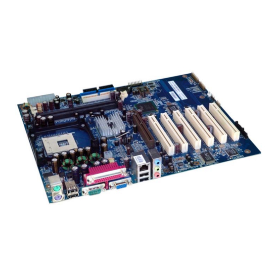
7 of 71 1. Introduction This manual describes the 886LCD/ATX(GV) and 886LCD/ATXU(GV) boards made by KONTRON Technology A/S. The boards will also be denoted 886LCD-GV family if no differentiation is required. All boards are to be used with the Intel® Pentium® 4, Intel Celeron® and Intel® Celeron® D Processors. -
Page 8: Installation Procedure
2. Installation procedure 2.1 Installing the board To get the board running, follow these steps. In some cases the board shipped from KONTRON Technology has CPU, DDR DRAM and Cooler mounted. In this case Step 2-4 can be skipped. 1. Turn off the power supply. -
Page 9: Requirement According To En60950
886LCD/ATX(GV) -/ATXU(GV) KTD-00647-C Public User Manual Date: 2007-02-08 Page 9 of 71 2.2 Requirement according to EN60950: Users of 886LCD-GV boards should take care when designing chassis interface connectors in order to fulfill the EN60950 standard: When an interface/connector has a VCC (or other power) pin, which is directly connected to a power plane like the VCC plane: To protect the external power lines of peripheral devices the customer has to take care about: •... -
Page 10: System Specification
1x 10/100Mbits/s LAN subsystem using the Realtek RTL8100C LAN controllers. LAN Support PXE netboot supported. Wake On LAN (WOL) supported. • Kontron Technology / AMI BIOS (core version 8.00) BIOS • Support for Advanced Configuration and Power Interface (ACPI 1.0, 2.0), Plug and... - Page 11 886LCD/ATX(GV) -/ATXU(GV) KTD-00647-C Public User Manual Date: 2007-02-08 Page 11 of 71 • PCI Rev 2.2 compliant with support for 33 MHz PCI operations Instantly • Suspend to RAM support Available PC Technology • PCI Bus routed to PCI slot(s) (PCI Local Bus Specification Revision 2.2) Expansion •...
-
Page 12: Processor Support Table
886LCD/ATX(GV) -/ATXU(GV) KTD-00647-C Public User Manual Date: 2007-02-08 Page 12 of 71 3.2 Processor support table. 886LCD/ATX(GV) and 886LCD/ATX(GV) boards are designed to support the following processors: Intel® Pentium® 4 Processors Intel® Celeron® D Processors Intel Celeron® Processors Intel Intel Cache Speed Single Pack... - Page 13 886LCD/ATX(GV) -/ATXU(GV) KTD-00647-C Public User Manual Date: 2007-02-08 Page 13 of 71 Intel Intel Cache Speed Single Pack OEM Product size Product Order Code Order Code Intel® Celeron® D Processors 3.20 GHz, 533MHz FSB 256K BX80546RE3200C RK80546RE088256 3.06 GHz, 533MHz FSB 256K BX80546RE3066C RK80546RE083256...
-
Page 14: System Memory Support
BIOS will attempt to configure the memory settings, but performance and reliability may be impacted. In general DDR SDRAM with higher speeds than 266MHz may be used (e.g. 333MHz or 400MHz), but it is recommended to run a qualification test before use or to use Kontron Technology validated DDR SDRAM. -
Page 15: System Overview
886LCD/ATX(GV) -/ATXU(GV) KTD-00647-C Public User Manual Date: 2007-02-08 Page 15 of 71 3.4 System overview The block diagram below shows the architecture and main components of the 886LCD boards. The two key ® ® components on the board are the Intel 845GV and Intel ICH4 Embedded Chipsets. -
Page 16: Power Consumption
886LCD/ATX(GV) -/ATXU(GV) KTD-00647-C Public User Manual Date: 2007-02-08 Page 16 of 71 3.5 Power Consumption This section describes static and dynamic power consumption on the 886LCD/ATXU(GV) board in a specific configuration: • 886LCD/ATXU(GV) • P4, 2.0GHz, 400MHz FSB, 256MByte L2 cache •... -
Page 17: Connector Definitions
886LCD/ATX(GV) -/ATXU(GV) KTD-00647-C Public User Manual Date: 2007-02-08 Page 17 of 71 4. Connector Definitions The following sections provide pin definitions and detailed description of all on-board connectors. The connector definitions follow the following notation: Column Description name Shows the pin-numbers in the connector. The graphical layout of the connector definition tables is made similar to the physical connectors. -
Page 18: Connector Layout
886LCD/ATX(GV) -/ATXU(GV) KTD-00647-C Public User Manual Date: 2007-02-08 Page 18 of 71 4.1 Connector layout 4.1.1 886LCD/ATXU(GV) CASE OPEN DIMM2 FLOPPY Clr-CMOS FRONT PANEL, CN5 DIMM1 IDE_P GAME/ MIDI, CN6 IDE_S ATXPWR USB2/3 (AGP)/DVO COM2 FAN1 SATA1 SATA0 FAN3 PCI SLOT 3 PCI SLOT 2 FAN2 PCI SLOT 1... -
Page 19: 886Lcd/Atx(Gv)
886LCD/ATX(GV) -/ATXU(GV) KTD-00647-C Public User Manual Date: 2007-02-08 Page 19 of 71 4.1.2 886LCD/ATX(GV) DIMM2 CASE OPEN DIMM1 FLOPPY FRONT PANEL, Clr-CMOS IDE_P GAME/ IDE_S USB2/3 MIDI, CN6 ATXPWR COM2 (AGP)/DVO SATA1 SATA0 FAN3 PCI SLOT 6 FAN2 PCI SLOT 5 ATXPWR +12V PCI SLOT 4... -
Page 20: Power Connector (Atxpwr, Atxpwr+12V)
886LCD/ATX(GV) -/ATXU(GV) KTD-00647-C Public User Manual Date: 2007-02-08 Page 20 of 71 4.2 Power Connector (ATXPWR, ATXPWR+12V) The 886LCD/ATX(GV) and 886LCD/ATXU(GV) is designed to be supplied from a standard ATX power supply. ATX Power Connector 886LCD/ATX(GV) and 886LCD/ATXU(GV) Pull Pull Note Ioh/Iol Type... -
Page 21: Keyboard And Ps/2 Mouse Connectors
886LCD/ATX(GV) -/ATXU(GV) KTD-00647-C Public User Manual Date: 2007-02-08 Page 21 of 71 4.3 Keyboard and PS/2 mouse connectors Attachment of a keyboard or PS/2 mouse adapter can be done through the stacked PS/2 mouse and keyboard connector (MSE & KBD). Both interfaces utilize open-drain signaling with on-board pull-up. -
Page 22: Display Connectors
886LCD/ATX(GV) -/ATXU(GV) KTD-00647-C Public User Manual Date: 2007-02-08 Page 22 of 71 4.4 Display Connectors The 886LCD board family provides onboard two basic types of interfaces to a display: Analog CRT interface and a digital interface typically used with flat panels. The digital interface to flat panels can be achieved through the DVO port available on the AGP connector by using a dedicated ADD card. -
Page 23: Agp)/Dvo Connector
886LCD/ATX(GV) -/ATXU(GV) KTD-00647-C Public User Manual Date: 2007-02-08 Page 23 of 71 4.4.2 (AGP)/DVO connector The 886LCD/ATX(GV) and 886LCD/ATXU(GV) boards are equipped with the Intel 845GV chipset. The GV chipset does not support AGP output, but only DVO output. Note Type Signal Signal... - Page 24 886LCD/ATX(GV) -/ATXU(GV) KTD-00647-C Public User Manual Date: 2007-02-08 Page 24 of 71 Signal Description – (AGP)/DVO Connector: Signal Description DVOB_CLK; DVOB Clock Output: These signals provide a differential pair reference clock that can run up to DVOB_CLK# 165 MHz. Formerly known by: DVOB_CLKOUT0=DVOB_CLK and DVOB_CLKOUT1=DVOB_CLK#.
-
Page 25: Parallel Ata Harddisk Interface
886LCD/ATX(GV) -/ATXU(GV) KTD-00647-C Public User Manual Date: 2007-02-08 Page 25 of 71 4.5 Parallel ATA harddisk interface Two parallel ATA harddisk controllers are available on the board – a primary and a secondary controller. Standard 3½” harddisks or CD-ROM drives may be attached to the primary and secondary controller board by means of the 40 pin IDC connectors, IDE_P and IDE_S. -
Page 26: Ide Hard Disk Connector (Ide_P)
886LCD/ATX(GV) -/ATXU(GV) KTD-00647-C Public User Manual Date: 2007-02-08 Page 26 of 71 4.5.1 IDE Hard Disk Connector (IDE_P) This connector can be used for connection of up till two primary IDE drives. Pull Pull Note Ioh/Iol Type Signal Signal Type Ioh/Iol Note RESETA#... -
Page 27: Serial Ata Harddisk Interface
886LCD/ATX(GV) -/ATXU(GV) KTD-00647-C Public User Manual Date: 2007-02-08 Page 27 of 71 4.6 Serial ATA harddisk interface Two serial ATA harddisk controllers are available on the board – a primary controller (SATA0) and a secondary controller (SATA1). 4.6.1 SATA Hard Disk Connector (SATA0, SATA1) SATA0, J16: Pull Signal... -
Page 28: Floppy Disk Connector (Fdc1)
886LCD/ATX(GV) -/ATXU(GV) KTD-00647-C Public User Manual Date: 2007-02-08 Page 28 of 71 Floppy Disk Connector (FDC1) Pull Pull Note Ioh/Iol Type Signal Signal Type Ioh/Iol Note DENSEL0# DS1# INDEX# 330R MOTEA# DRVB# DRVA# MOTEB# DIR# STEP# WDATA# WGATE# TRK0# 330R WPT# 330R RDATA#... -
Page 29: Printer Port Connector (Printer)
886LCD/ATX(GV) -/ATXU(GV) KTD-00647-C Public User Manual Date: 2007-02-08 Page 29 of 71 4.8 Printer Port Connector (PRINTER). The printer port connector is provided in a standard DB25 pinout. The signal definition in standard printer port mode is as follows: Pull Pull Note Ioh/Iol... -
Page 30: Serial Ports
886LCD/ATX(GV) -/ATXU(GV) KTD-00647-C Public User Manual Date: 2007-02-08 Page 30 of 71 4.9 Serial Ports Two RS232 serial ports (EIA/TIA-232-E compliant) are available on the 886LCD/ATX(GV) and 886LCD/ATXU(GV). The typical interpretation of the signals in the COM ports is as follows: Serial output. -
Page 31: Ethernet Connector
886LCD/ATX(GV) -/ATXU(GV) KTD-00647-C Public User Manual Date: 2007-02-08 Page 31 of 71 4.10 Ethernet connector. The 886LCD/ATX(GV) and 886LCD/ATXU(GV) boards supports 1 channel of 10/100Mb Ethernet using the Realtek 8100C LAN controller. In order to achieve the specified performance of the Ethernet port, Category 5 twisted pair cables must be used with 10/100MB LAN networks. -
Page 32: Usb Connector (Usb)
886LCD/ATX(GV) -/ATXU(GV) KTD-00647-C Public User Manual Date: 2007-02-08 Page 32 of 71 4.11 USB Connector (USB) The 886LCD/ATX(GV) and 886LCD/ATXU(GV) contains three USB (Universal Serial Bus) ports UHCI Host Controllers. Each Host Controller includes a root hub with two separate USB ports each, for a total of 6 USB ports. -
Page 33: Usb Connector 2/3 (Usb2/3)
886LCD/ATX(GV) -/ATXU(GV) KTD-00647-C Public User Manual Date: 2007-02-08 Page 33 of 71 4.11.2 USB Connector 2/3 (USB2/3). USB2 and USB3 are located on a a 2x5 pinrow connector. The pinout of the USB2/3 connector (USB2) is as follows: Pull Pull Note Ioh/Iol Type... -
Page 34: 886Lcd/Atx(Gv) -/Atxu(Gv)
886LCD/ATX(GV) -/ATXU(GV) KTD-00647-C Public User Manual Date: 2007-02-08 Page 34 of 71 4.12 Audio Connector 4.12.1 Audio Line-in, Line-out and Microphone Audio Line-in, Line-out and Microphone are available in the stacked audio jack connector. Signal Type Note Line in – Left RING Line in –... -
Page 35: Fan Connectors, Cpu Fan, Chassis Fan, Pwr Fan
886LCD/ATX(GV) -/ATXU(GV) KTD-00647-C Public User Manual Date: 2007-02-08 Page 35 of 71 4.13 Fan connectors, CPU FAN, CHASSIS FAN, PWR FAN. The CPU FAN (FAN3) is used for connection of the active cooler for the CPU. The CHASSIS FAN (FAN2) can be used to power, control and monitor a fan for chassis ventilation etc. Pull Signal Type... -
Page 36: The Clear Cmos Jumper, Clr-Cmos
886LCD/ATX(GV) -/ATXU(GV) KTD-00647-C Public User Manual Date: 2007-02-08 Page 36 of 71 4.14 The Clear CMOS Jumper, Clr-CMOS. The Clear CMOS Jumper is used to clear the CMOS content. To clear all CMOS settings, including Password protection, move the Clear CMOS jumper (with or without power on the system) for approximately 1 minute. -
Page 37: Case Open, S1
886LCD/ATX(GV) -/ATXU(GV) KTD-00647-C Public User Manual Date: 2007-02-08 Page 37 of 71 4.16 Case Open, S1 The Case Open connector can be used for Intrusion Detection. If Case is opened the switch should be closed. Pull Pull Note Ioh/Iol Type Signal Signal Type... -
Page 38: Front Panel Connector, Cn5
886LCD/ATX(GV) -/ATXU(GV) KTD-00647-C Public User Manual Date: 2007-02-08 Page 38 of 71 4.18 Front Panel connector, CN5. Pull Pull Note Ioh/Iol Type Signal Signal Type Ioh/Iol Note GRN LED+ PWR LED+ GRN LED+ PWR LED+ GRN LED- HDD LED+ KBLOCK# HDD LED- HDD LED- 11 12... -
Page 39: Game / Midi Connector, Cn6
886LCD/ATX(GV) -/ATXU(GV) KTD-00647-C Public User Manual Date: 2007-02-08 Page 39 of 71 4.19 GAME / MIDI Connector, CN6 Pull Pull Note Ioh/Iol Type Signal Signal Type Ioh/Iol Note J1BUTTON1 J2BUTTON1 MIDI_OUT 11 12 J2BUTTON2 J1BUTTON2 13 14 MIDI_IN 15 16 Signal Description J1BUTTON1... -
Page 40: Wol Connector (W.o.l)
886LCD/ATX(GV) -/ATXU(GV) KTD-00647-C Public User Manual Date: 2007-02-08 Page 40 of 71 4.21 WOL Connector (W.O.L). Pull Note Ioh/Iol Type Signal 5V/SB5V PME# Signal Description Wake on LAN from an external LAN adapter is supported through this signal. Connect PME# the W.O.L. -
Page 41: Pci Slot 1, Slot 2 And Slot 3 Connectors
886LCD/ATX(GV) -/ATXU(GV) KTD-00647-C Public User Manual Date: 2007-02-08 Page 41 of 71 4.23 PCI Slot 1, Slot 2 and Slot 3 connectors. 4.23.1 PCI Slot Connector Terminal Note Type Signal Signal Type Note -12V TRST# +12V INTA# INTB# INTC# INTD# REQ2# CLKC REQ3#... -
Page 42: Signal Description -Pci Slot Connector
886LCD/ATX(GV) -/ATXU(GV) KTD-00647-C Public User Manual Date: 2007-02-08 Page 42 of 71 4.23.2 Signal Description –PCI Slot Connector SYSTEM PINS Clock provides timing for all transactions on PCI and is an input to every PCI device. All other PCI signals, except RST#, INTA#, INTB#, INTC#, and INTD#, are sampled on the rising edge of CLK and all other timing parameters are defined with respect to this edge. -
Page 43: 886Lcd/Atx(Gv) And 886Lcd/Atxu(Gv) Pci Irq & Int Routing
886LCD/ATX(GV) -/ATXU(GV) KTD-00647-C Public User Manual Date: 2007-02-08 Page 43 of 71 ARBITRATION PINS (BUS MASTERS ONLY) Request indicates to the arbiter that this agent desires use of the bus. This is a point to point signal. REQ# Every master has its own REQ# which must be tri-stated while RST# is asserted. Grant indicates to the agent that access to the bus has been granted. -
Page 44: System Resources
886LCD/ATX(GV) -/ATXU(GV) KTD-00647-C Public User Manual Date: 2007-02-08 Page 44 of 71 5. System Resources 5.1 Memory map The table below lists the system memory map. Address range (hex) Size Description 00000000- 0007FFFF 512 Kbytes Conventional memory 00080000- 0009FBFF 127 Kbyte Extended conventional memory 0009FC00- 0009FFFF... -
Page 45: Interrupt Usage
886LCD/ATX(GV) -/ATXU(GV) KTD-00647-C Public User Manual Date: 2007-02-08 Page 45 of 71 5.3 Interrupt Usage Notes • • IRQ0 • IRQ1 • IRQ2 • • IRQ3 • • IRQ4 • • • • • • • • IRQ5 • IRQ6 •... -
Page 46: I/O Map
886LCD/ATX(GV) -/ATXU(GV) KTD-00647-C Public User Manual Date: 2007-02-08 Page 46 of 71 5.4 I/O Map Address (hex) Size Description 0020- 0021 Programmable interrupt controller 0040- 0043 System Timer 0060- 0060 Standard keyboard 0061- 0061 System speaker 0070- 0071 System CMOS/Real time clock 0170- 01F7 Secondary Parallel ATA IDE Channel... -
Page 47: Overview Of Bios Features
6. Overview of BIOS features This Manual section details specific BIOS features for the 886LCD/ATX(GV) and 886LCD/ATX(GV) boards. The BIOS are based on the AMI BIOS core version 8 with Kontron BIOS extensions. 6.1.1 System Management BIOS (SMBIOS / DMI) SMBIOS is a Desktop Management Interface (DMI) compliant method for managing computers in a managed network. -
Page 48: Bios Configuration / Setup
886LCD/ATX(GV) -/ATXU(GV) KTD-00647-C Public User Manual Date: 2007-02-08 Page 48 of 71 7. BIOS Configuration / Setup 7.1 Introduction The BIOS Setup is used to view and configure BIOS settings for the 886LCD/ATX(GV) and 886LCD/ATXU(GV) boards. The BIOS Setup is accessed by pressing the DEL key after the Power-On Self- Test (POST) memory test begins and before the operating system boot begins. -
Page 49: Advanced Menu
886LCD/ATX(GV) -/ATXU(GV) KTD-00647-C Public User Manual Date: 2007-02-08 Page 49 of 71 7.3 Advanced Menu BIOS Setup Utility Main Advanced PCIPnP Boot Security Chipset Power Exit Configure CPU. Advanced Settings Warning: Setting wrong values in below sections May cause system to malfunction. >... -
Page 50: Advanced Settings - Ide Configuration
886LCD/ATX(GV) -/ATXU(GV) KTD-00647-C Public User Manual Date: 2007-02-08 Page 50 of 71 7.3.2 Advanced settings – IDE Configuration BIOS Setup Utility Main Advanced PCIPnP Boot Security Chipset Power Exit IDE Configuration DISABLED: disables the integrated IDE OnBoard PCI IDE Controller [Both] Controller. - Page 51 886LCD/ATX(GV) -/ATXU(GV) KTD-00647-C Public User Manual Date: 2007-02-08 Page 51 of 71 BIOS Setup Utility Advanced Select the type of Primary IDE Master devices connected to Device :Hard Disk the system Vendor :ST340014A Size :40.0GB LBA Mode :Supported Block Mode :16Sectors PIO Mode Async DMA...
-
Page 52: Advanced Settings - Floppy Configuration
886LCD/ATX(GV) -/ATXU(GV) KTD-00647-C Public User Manual Date: 2007-02-08 Page 52 of 71 7.3.3 Advanced settings – Floppy Configuration BIOS Setup Utility Main Advanced PCIPnP Boot Security Chipset Power Exit Floppy Configuration Select the type of floppy drive Floppy A [Disabled] connected to the Floppy B [Disabled]... -
Page 53: Advanced Settings - Superio Configuration
886LCD/ATX(GV) -/ATXU(GV) KTD-00647-C Public User Manual Date: 2007-02-08 Page 53 of 71 7.3.4 Advanced settings – SuperIO Configuration BIOS Setup Utility Main Advanced PCIPnP Boot Security Chipset Power Exit Configure Win627THF Super IO Chipset Allows BIOS to Enable or Disable Floppy OnBoard Floppy Controller [Disabled] Controller. -
Page 54: Advanced Settings - Hardware Health Configuration
886LCD/ATX(GV) -/ATXU(GV) KTD-00647-C Public User Manual Date: 2007-02-08 Page 54 of 71 7.3.5 Advanced settings – Hardware Health Configuration BIOS Setup Utility Main Advanced PCIPnP Boot Security Chipset Power Exit Hardware Health Event Monitoring Enable Hardware Health Monitoring H/W Health Function [Enabled] Device. -
Page 55: Advanced Settings - Acpi Configuration
886LCD/ATX(GV) -/ATXU(GV) KTD-00647-C Public User Manual Date: 2007-02-08 Page 55 of 71 7.3.6 Advanced settings – ACPI Configuration BIOS Setup Utility Main Advanced PCIPnP Boot Security Chipset Power Exit ACPI Aware O/S [Yes] Enable / disable ACPI support for > General ACPI Configuration Operating System >... -
Page 56: Advanced Settings - General Acpi Configuration
886LCD/ATX(GV) -/ATXU(GV) KTD-00647-C Public User Manual Date: 2007-02-08 Page 56 of 71 7.3.7 Advanced settings – General ACPI Configuration BIOS Setup Utility Main Advanced PCIPnP Boot Security Chipset Power Exit General ACPI Configuration Select the ACPI state used for System Suspend mode [S1 &... -
Page 57: Advanced Settings - Advanced Acpi Configuration
886LCD/ATX(GV) -/ATXU(GV) KTD-00647-C Public User Manual Date: 2007-02-08 Page 57 of 71 7.3.8 Advanced settings – Advanced ACPI Configuration BIOS Setup Utility Main Advanced PCIPnP Boot Security Chipset Power Exit Advanced ACPI Configuration Enable RSDP pointers to 64-bit Fixed ACPI 2.0 Features [No] System Description ACPI APIC support... -
Page 58: Advanced Settings - Usb Configuration
886LCD/ATX(GV) -/ATXU(GV) KTD-00647-C Public User Manual Date: 2007-02-08 Page 58 of 71 7.3.9 Advanced settings – USB Configuration BIOS Setup Utility Main Advanced PCIPnP Boot Security Chipset Power Exit USB Configuration Enables support for Legacy USB. AUTO Module Version – 2.23.2-6.4 Option disables Legacy support if USB Devices Enabled :... -
Page 59: Advanced Settings - Usb Mass Storage Device Configuration
886LCD/ATX(GV) -/ATXU(GV) KTD-00647-C Public User Manual Date: 2007-02-08 Page 59 of 71 7.3.10 Advanced settings – USB Mass Storage Device Configuration BIOS Setup Utility Main Advanced PCIPnP Boot Security Chipset Power Exit USB Mass Storage Device Configuration Enables USB host controllers. -
Page 60: Pcipnp Menu
886LCD/ATX(GV) -/ATXU(GV) KTD-00647-C Public User Manual Date: 2007-02-08 Page 60 of 71 7.4 PCIPnP Menu BIOS Setup Utility Main Advanced PCIPnP Boot Security Chipset Power Exit NO: lets the BIOS Advanced PCI/PnP Settings configure all the Warning: Setting wrong values in below sections devices in the May cause system to malfunction. -
Page 61: Boot Menu
886LCD/ATX(GV) -/ATXU(GV) KTD-00647-C Public User Manual Date: 2007-02-08 Page 61 of 71 7.5 Boot Menu BIOS Setup Utility Main Advanced PCIPnP Boot Security Chipset Power Exit Boot Settings Configure Settings during System Boot. > Boot Settings Configuration Boot Device [PM-ST3120022A] Boot Device FLOPPY DRIVE] Boot Device... -
Page 62: Boot - Boot Settings Configuration
886LCD/ATX(GV) -/ATXU(GV) KTD-00647-C Public User Manual Date: 2007-02-08 Page 62 of 71 7.5.1 Boot – Boot Settings Configuration BIOS Setup Utility Main Advanced PCIPnP Boot Security Chipset Power Exit Configure Settings Boot Settings during System Boot. Quick Boot [Enabled] Quiet Boot [Disabled] AddOn ROM Display Mode [force BIOS]... -
Page 63: Security Menu
886LCD/ATX(GV) -/ATXU(GV) KTD-00647-C Public User Manual Date: 2007-02-08 Page 63 of 71 7.6 Security Menu BIOS Setup Utility Main Advanced PCIPnP Boot Security Chipset Power Exit Security Settings Install or Change the password. Supervisor Password :Installed User Password :Installed Change Supervisor Password User Access Level [Full Access] Change User Password... -
Page 64: Chipset Menu
886LCD/ATX(GV) -/ATXU(GV) KTD-00647-C Public User Manual Date: 2007-02-08 Page 64 of 71 7.7 Chipset Menu BIOS Setup Utility Main Advanced PCIPnP Boot Security Chipset Power Exit Intel Brookdale-G Advanced Chipset Settings NorthBridge chipset configuration Warning: Setting wrong values in below sections may options. -
Page 65: Advanced Chipset Settings - Intel Brookdale-G Northbridge Configuration
886LCD/ATX(GV) -/ATXU(GV) KTD-00647-C Public User Manual Date: 2007-02-08 Page 65 of 71 7.7.1 Advanced Chipset Settings – Intel Brookdale-G NorthBridge Configuration BIOS Setup Utility Main Advanced PCIPnP Boot Security Chipset Power Exit Select which graphics Configure advanced settings for NorthBrigde controller to use as Primary Video Device [Auto]... -
Page 66: Advanced Chipset Settings - Southbridge Configuration
886LCD/ATX(GV) -/ATXU(GV) KTD-00647-C Public User Manual Date: 2007-02-08 Page 66 of 71 7.7.2 Advanced Chipset Settings – SouthBridge Configuration BIOS Setup Utility Main Advanced PCIPnP Boot Security Chipset Power Exit Enable / Disable the ICH4 IOAPIC function. Onboard IDE [Enabled] SMBUS [Enabled] AC´97 Audio... -
Page 67: Power Menu
886LCD/ATX(GV) -/ATXU(GV) KTD-00647-C Public User Manual Date: 2007-02-08 Page 67 of 71 7.8 Power Menu BIOS Setup Utility Main Advanced PCIPnP Boot Security Chipset Power Exit Enable/Disable SMI based power APM Configuration management and APM support. Power Management/APM [Enabled] Power Button Mode [On/Off] Restore on AC Power Loss [Last state]... -
Page 68: Exit Menu
886LCD/ATX(GV) -/ATXU(GV) KTD-00647-C Public User Manual Date: 2007-02-08 Page 68 of 71 7.9 Exit Menu BIOS Setup Utility Main Advanced PCIPnP Boot Security Chipset Power Exit Exit system setup Exit Options after saving the changes. Save Changes and Exit Discard Changes and Exit F10 Key can be used Discard Changes for this operation. -
Page 69: Ami Bios Beep Codes
886LCD/ATX(GV) -/ATXU(GV) KTD-00647-C Public User Manual Date: 2007-02-08 Page 69 of 71 7.10 AMI BIOS Beep Codes Boot Block Beep Codes: Number of Description Beeps Insert diskette in floppy drive A: ‘AMIBOOT.ROM’ file not found in root directory of diskette in A: Base Memory error Flash Programming successful Floppy read error... -
Page 70: Os Setup
User Manual Date: 2007-02-08 Page 70 of 71 8. OS setup Use the Setup.exe files for all relevant drivers. The drivers can be found on the 886LCD/ATXU(GV) and 886LCD/ATX(GV) Driver CD or they can be downloaded from the homepage http://www.kontron-emea.com... -
Page 71: Ktd-00647-C
71 of 71 9. Warranty KONTRON Technology warrants its products to be free from defects in material and workmanship during the warranty period. If a product proves to be defective in material or workmanship during the warranty period, KONTRON Technology will, at its sole option, repair or replace the product with a similar product.
Need help?
Do you have a question about the 886LCD/ATX(GV) and is the answer not in the manual?
Questions and answers