LXE MX3-CE User Manual
Hide thumbs
Also See for MX3-CE:
- Reference manual (240 pages) ,
- Reference manual (244 pages) ,
- Reference manual (166 pages)
Table of Contents
Advertisement
Quick Links
Download this manual
See also:
Reference Manual
MX3-CE User's Guide
®
®
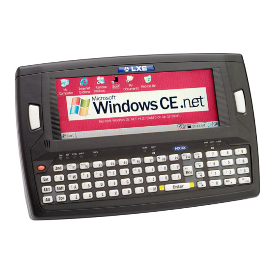
(MX3 mobile device running Microsoft
Windows
CE 3.0 Operating System)
IMPORTANT NOTICE
LXE's MX3-CE is obsolete. This electronic manual has been made available as a
courtesy to LXE's MX3-CE customers. Please contact your LXE customer support
representative for assistance.
Copyright © June 2005 by LXE Inc.
All Rights Reserved
MX3CEA136OPGD
E-EQ-MX3CEOGWW-F-ARC
Advertisement
Table of Contents

Related Manuals for LXE MX3-CE


Summary of Contents for LXE MX3-CE
- Page 1 Windows CE 3.0 Operating System) IMPORTANT NOTICE LXE’s MX3-CE is obsolete. This electronic manual has been made available as a courtesy to LXE's MX3-CE customers. Please contact your LXE customer support representative for assistance. Copyright © June 2005 by LXE Inc.
- Page 2 Language: English Notices LXE Inc. reserves the right to make improvements or changes in the products described in this manual at any time without notice. While reasonable efforts have been made in the preparation of this document to assure its accuracy, LXE assumes no liability resulting from any errors or omissions in this document, or from the use of the information contained herein.
-
Page 3: Table Of Contents
Set The Display Contrast ........................12 Set the Display Backlight Timer ......................12 Set the Display Blanking Timer......................13 Set the MX3-CE Power Off Timer ..................... 14 Saving Settings............................ 14 Set The Audio Speaker Volume......................15 Using the Keypad ..........................15 Using the Touch Screen........................ - Page 4 RS-232 Connector ..........................34 Vehicle Mount Cradle ......................... 35 Status LED............................35 Power Connector ..........................36 RS-232 Connector ..........................36 PPENDIX Keypad ........................39 Key Map 101-Key Equivalencies ....................... 39 PPENDIX EGULATORY OTICES AND AFETY NFORMATION NDEX MX3-CE User’s Guide E-EQ-MX3CEOGWW-F-ARC...
- Page 5 Table of Contents Illustrations Figure 1 CDRH / IEC 825 Caution Label Location - MX3-CE, Back ..............3 Figure 2 Caution Label - Scanner ........................3 Figure 3 Hardware Configuration........................4 Figure 4 Front of MX3-CE ..........................5 Figure 5 Endcap ..............................6 Figure 6 Back of MX3-CE...........................6 Figure 7 MX3-CE Battery Contacts........................7...
- Page 6 Table of Contents MX3-CE User’s Guide E-EQ-MX3CEOGWW-F-ARC...
-
Page 7: Introduction
Li-Ion batteries (like all batteries) gradually lose their capacity over time (in a linear fashion) and never just stop working. This is important to remember -- the MX3-CE is always 'on' even when in the Suspend state and draws battery power at all times. Use the Start | Settings | Control Panel | Power Properties | Charge tab to check the battery status and power reading. -
Page 8: Document Conventions
Keyword that indicates a potentially hazardous situation which, if not avoided, could result in death or serious injury. DANGER Keyword that indicates a imminent hazardous situation which, if not avoided, will result in death or serious injury. MX3-CE Environmental Specifications Feature Specification Monochrome display : -4°F to 122°F (20°C to 50°C) [non-condensing] Operating Temperature Color display : 32°F to 122°F (0°C to 50°C) [non-condensing]... -
Page 9: Laser Warnings And Labels
• Do not stare directly into the laser beam. • Do not remove the laser caution labels from the MX3-CE. • Do not connect the laser barcode window to any other device. The laser barcode window is certified for use with the MX3-CE only. -
Page 10: Quick Start
LXE MX3-CE. In general, the sequence of events is: 1. Insert a fully charged battery. (Always put a fully charged battery in the MX3-CE at the beginning of the shift or workday.) 2. -
Page 11: Components
Quick Start Components Figure 4 Front of MX3-CE Endcap Shift LED Touch Screen Display Caps LED Scan or Enter (programmable) Scanner LED Beeper Backup Battery LED On/Off Button Status LED 2nd LED Main Battery LED Alt LED Charger LED Ctrl LED... -
Page 12: Figure 5 Endcap
Quick Start Figure 5 Endcap DC Power Jack Com 1 (Serial or USB) Port Com 3 (Serial or Scanner) Port Audio Jack Figure 6 Back of MX3-CE Endcap Cradle Input Contacts Leather Handstrap Connector Main Battery IR Port (Com 2 Port) Stylus MX3-CE User’s Guide... -
Page 13: Insert Main Battery
MX3-CE. Figure 7 MX3-CE Battery Contacts The MX3-CE Battery Compartment is located at the bottom of the back of the computer. The arrows in the figure above point to the battery and cradle contacts in the computer. Figure 8 Main Battery Place the battery in the compartment, making sure the side of the battery with six contacts matches up with the battery contacts in the computer battery compartment. -
Page 14: Power Button
Carefully remove the paper backing from the Stylus Clip sticky. Firmly press the sticky side of the clip onto the MX3-CE and hold in place for 15 seconds. Thread the tether through the end of the stylus and tie the ends firmly to the Stylus Clip so that the ends don’t interfere with placing the stylus in the Stylus Clip. -
Page 15: Connect External Power Supply (Optional)
• US AC/DC 12V Power Supply • Cigarette Lighter Adapter • International AC/DC 12V Power Supply The MX3-CE DC power jack is located on the endcap. The cradle power jack is located on the back of the cradle. Figure 10 Connect External Power Supply Insert the barrel connector into the MX3-CE power jack and push in firmly. -
Page 16: Attach Hand Strap (Optional)
1. Place the MX3-CE, with the screen facing down, on a flat stable surface. 2. Attach the hand strap to the MX3-CE with the screws and washers provided. 3. Test the strap's connection making sure the MX3-CE is securely connected to each end of the strap. -
Page 17: Tapping The Touchscreen With A Stylus
• Place the cursor in a text box prior to typing in data or retrieving data using the integrated barcode scanner or an input/output device connected to the serial port. An extra or replacement stylus can be ordered from LXE. See the section titled "Accessories" for the stylus part number. -
Page 18: Set The Display Contrast
OK to save the changes. The first option may be set when the MX3-CE will be running on battery power only. The second option may be set when the MX3-CE will be running on external power (e.g. AC adapter, cigarette adapter, powered cradle). -
Page 19: Set The Display Blanking Timer
OK to save the changes. The first option may be set when the MX3-CE will be running on battery power only. The second option may be set when the MX3-CE will be running on external power (e.g. AC adapter, cigarette adapter, powered cradle). -
Page 20: Set The Mx3-Ce Power Off Timer
OK to save the changes. The first option may be set when the MX3-CE will be running on battery power only. The second option may be set when the MX3-CE will be running on external power (e.g. AC adapter, cigarette adapter, powered cradle). -
Page 21: Set The Audio Speaker Volume
The audio volume can be adjusted to a comfortable level for the user. The volume is increased or decreased one step each time the volume key is pressed. The MX3-CE has an internal speaker and a jack for an external headset. -
Page 22: Enter Data
The keypad is used to manually input data that is not collected otherwise. Almost any function that a full sized computer keyboard can provide is duplicated on the MX3-CE keypad but it may take a few more keystrokes to accomplish a keyed task. -
Page 23: Scanner Entry
Align the red beam so that the barcode is centered within the beam. The laser beam must cross the entire barcode. Move the MX3-CE towards or away from the barcode so that the barcode takes up approximately two-thirds the width of the beam. -
Page 24: Charge Battery In Mx3 Multi-Charger
Insert the Main Battery into any charging cup in the Multi-Charger. The retaining clip will snap the battery into place in the charging cup. Do not "slam" or slide the battery into the charging cup. Failure to follow these instructions can result in damage to the main battery or the Multi-Charger. MX3-CE User’s Guide E-EQ-MX3CEOGWW-F-ARC... -
Page 25: Getting Help
Getting Help Getting Help All LXE user guides are now available on one CD and they can also be viewed/downloaded from the LXE ServicePass website. Contact your LXE representative to obtain the LXE Manuals CD. You can also get help from LXE by calling the telephone numbers listed on the LXE Manuals CD, in the file titled "Contacting LXE". - Page 26 Note: When using the 8500 Series tethered scanners (LS3408), the tethered scanner Power Mode must be set to “Reduced Power Mode”to conserve MX3-CE battery life. The reduced power mode setting will not impact performance of the 8500 series scanner. The default mode is “Continuous On”. Please refer to the manufacturer’s user guide for instruction.
-
Page 27: The Mx3-Ce Hand Held Computer
Touch Screen Display Figure 20 MX3-CE Touch Screen Display The MX3-CE Touch Screen Display is an LCD unit capable of supporting VGA graphics modes. Display size is 640 x 240 pixels. The display covering is designed to resist stains. The touch screen allows signature capture and touch input. -
Page 28: Touch Screen Calibration
Touch Screen Display Touch Screen Calibration If the MX3-CE is not responding properly to pen touch taps, the touch screen may need to be recalibrated. Contact your System Administrator for assistance. To recalibrate the screen, select Start | Settings | Control Panel | Stylus | Calibration. -
Page 29: Programmable Buttons
Programmable Buttons The default setting for the right button is Enter. The default setting for the left button is Scan. When the MX3-CE does not have an integrated scanner, both buttons function as Enter keys. Scan Pressing this key activates the integrated laser scanner, if installed. See the section titled "Scan Key Function."... -
Page 30: Endcaps And Com Ports
Figure 23 Endcap Connectors The COM 2 port is always the IR port on the back of the MX3-CE, regardless of the type of endcap installed. COM 2 can only be accessed when a tethered scanner is connected to the RS- 232 port on the cradle, and the MX3-CE is in the cradle. -
Page 31: Tethered Scanners
Tethered scanners read barcode scans only when the trigger on the tethered scanner is pressed. To set the MX3-CE to use a tethered scanner, select Start | Settings | Control Panel | Scanner | COM1 (2 or 3). Click the "Power on Pin 9 (+5V)" checkbox for the COM port selected. -
Page 32: The Keypad
The keymaps (keypress sequences) are located in “Appendix A - Key Maps.” Scan Key Function (MX3-CE's with Scanner endcaps only.) The Scan key activates the scanner when a scanner endcap is installed and the Scan button is pressed. The internal scanner scans only when the Scan button is pressed. -
Page 33: Alt Key Function
• No CapsLock AND No Shift keypress – result is a lowercase letter. • CapsLock OR Shift – result is an uppercase letter. • CapsLock AND Shift keypress – result is a lowercase letter. Keypress Sequences See Appendix A for key maps for all keypads. E-EQ-MX3CEOGWW-F-ARC MX3-CE User’s Guide... -
Page 34: Keypad Led Functions
MX3-CE is seated in a powered cradle. • Red - Main Battery is charging. • Green - battery charge is complete and the MX3-CE is connected to external power through the power jack or a powered cradle. -
Page 35: Batteries
RF transmitter, the shorter the time required between battery recharges. The MX3-CE keeps date and time valid for a minimum of four days using a fully charged Backup Battery and a Main Battery that has reached the Low Warning point. -
Page 36: Backup Battery
Replacement is performed by LXE. Note: An uninterrupted external power source (wall AC adapters or DC/DC converters) transfers power to the MX3-CE internal charging circuitry which, in turn, recharges the Main Battery and Backup Battery. Battery Hot-Swapping When the battery power level is low, the BATT-M LED illuminates and remains on. -
Page 37: Battery Chargers
The MX3-CE DC power jack is located on the endcap. The cradle power jack is located on the back of the cradle.The MX3-CE (and the Desktop Cradle) connect to any of the following power supplies through the DC Power Jack. -
Page 38: Cradles
MX3-CE and, in turn, the MX3-CE recharges the Main Battery. The MX3-CE can be either on or in Suspend mode while in the cradle. The MX3-CE can be inserted and removed from the cradle with one hand. -
Page 39: Status Led
LXE US AC Adapter or an LXE International AC Adapter. When powered, the cradle transfers power to the internal charging circuitry of the MX3-CE allowing it to recharge the Main Battery. A powered cradle supports RS-232 and IR communications. -
Page 40: Rs-232 Connector
RS-232 Connector Figure 34 Desktop Cradle RS-232 Connector The RS-232 connector is located on the back of the cradle. When the MX3-CE is properly docked, the bi-directional half-duplex transceivers in the MX3-CE and cradle are aligned through their IR windows. The half-duplex IR signals from the MX3-CE are converted to RS-232 signals in the cradle and available at this connector. -
Page 41: Vehicle Mount Cradle
The MX3-CE is removed from the cradle by pressing the release mechanisms and pulling the MX3-CE up and away from the cradle. -
Page 42: Power Connector
RS-232 Connector Figure 37 Vehicle Cradle RS-232 Connector The RS-232 connector is located on the back of the cradle. When the MX3-CE is properly docked, the bi-directional half-duplex transceivers in the MX3-CE and cradle are aligned through their IR windows. The half-duplex IR signals from the MX3-CE are converted to RS-232 signals in the cradle and available at this connector. - Page 43 Care must be taken to avoid bending or warping the bottom “U” shaped bracket when attaching the cradle to a lift truck or other vehicle. A bent “U” bracket can over-compress or over-extend the rubber isolators leading to failure of the isolators. E-EQ-MX3CEOGWW-F-ARC MX3-CE User’s Guide...
- Page 44 Cradles MX3-CE User’s Guide E-EQ-MX3CEOGWW-F-ARC...
-
Page 45: Appendixa Key Maps
Figure 38 QWERTY Keypad Key Map 101-Key Equivalencies Note: This key mapping is used on hand held computers that are NOT running an LXE Terminal Emulator. When using a sequence of keys that includes the 2 key, press the 2 key first then the rest of the key sequence. - Page 46 BackTab Break Pause Up Arrow Up Arrow Down Arrow Down Arrow Right Arrow Right Arrow Left Arrow Left Arrow Insert BkSp Delete Home Left Arrow Right Arrow Page Up Up Arrow Page Down Down Arrow ScrollLock MX3-CE User’s Guide E-EQ-MX3CEOGWW-F-ARC...
- Page 47 Key Maps Press These Keys and Then To get this key Press this key Shift Ctrl CapsLock E-EQ-MX3CEOGWW-F-ARC MX3-CE User’s Guide...
- Page 48 Key Maps Press These Keys and Then To get this key Press this key Shift Ctrl CapsLock < > : (colon) ; (semicolon) _ (underscore) MX3-CE User’s Guide E-EQ-MX3CEOGWW-F-ARC...
- Page 49 Key Maps Press These Keys and Then To get this key Press this key Shift Ctrl CapsLock , (comma) ‘ (apostrophe) ~ (tilde) “ & E-EQ-MX3CEOGWW-F-ARC MX3-CE User’s Guide...
- Page 50 Key Maps MX3-CE User’s Guide E-EQ-MX3CEOGWW-F-ARC...
-
Page 51: Appendixb Regulatory Notices And Safety Information
Operation of this equipment in a residential area is likely to cause harmful interference in which case the user will be required to correct the interference at his own expense. Warning: Changes or modifications to this device not expressly approved by LXE, Inc., could void the user’s authority to operate this equipment. - Page 52 Information to User A label on the exterior of the device should resemble one of the labels shown below (the label contains the LXE part number of the installed radio card). The labels shown below and affixed to the device, identify where the device may be used and where its use is restricted.
- Page 53 Safety of information technology equipment, including electrical business equipment + Amendments A1..A4 We, LXE Inc., declare that the equipment specified above complies with all Essential Health and Safety Requirements of the above Directives and Standards, as amended. Signed: Place: LXE Inc., Norcross GA USA...
- Page 54 Safety of information technology equipment, including electrical business equipment + Amendments A1..A4 We, LXE Inc., declare that the equipment specified above complies with all Essential Health and Safety Requirements of the above Directives and Standards, as amended. Signed: Place: LXE Inc., Norcross GA USA R.
- Page 55 EN 60950-2: 1992 + A1..A4 Safety of information technology equipment, including electrical business equipment We, LXE Inc., declare that the equipment specified above complies with all Essential Health and Safety Requirements of the above Directives and Standards, as amended. Place LXE Inc., Norcross GA USA...
- Page 56 With regard to the use of external antennas The LXE 6726 can be equipped with external antennas. The antennas listed have been evaluated with the LXE 6726 pursuant to ETSI EN 300 328, and therefore meet the definition of ‘dedicated antenna’ per ERC/REC 70-03 Appendix 1 Table 3; thus the requirement set forth in ERC/REC 70-03 , Annex 3 are met by the LXE model 6726 transceiver.
- Page 57 EN60950-1: 2001 business equipment The product carries the CE Mark: We, LXE Inc., declare that the equipment specified above complies with all Essential Health and Safety Requirements of the above Directives and Standards, as amended. Date of issue: June 18, 2003 Cyril A.
- Page 58 With regard to the use of external antennas The LXE 6816 can be equipped with external antennas. The antennas listed have been assessed with the LXE 6816 pursuant to EN 300 328, and therefore meet the definition of ‘dedicated antenna’. The table below lists the maximum output power setting for the radio module in order to result in a total EIRP of 100mW or less.
- Page 59 Legend: Danish – DK; English – US; Finnish – FI; French- - FR; German – DE; Greek – GR; Italian – IT; Norwegian – NO; Portuguese – PT; Spanish – ES; Swedish – SE; Turkish – TR. E-EQ-MX3CEOGWW-F-ARC MX3-CE User’s Guide...
-
Page 60: Laser Light Safety Statement
Este producto usa luz de láser. Las etiquetas se proveen en la máquina exploradora. Por favor, lea detenidamente la explicación para las precauciones. (ES) Waarschuwing: Dit product gebruikt laserlicht. Een van de volgende labels is op de scanner aangebracht. Lees a.u.b. de waarschuwing onder Oppassen. (NL) MX3-CE User’s Guide E-EQ-MX3CEOGWW-F-ARC... - Page 61 üstünde saðlanýr. Lütfen Dikkat ifadesini okuyun. (TR) (GR) (JP) (KR) Legend: Chinese-CN; Danish-DK; Dutch-NL; English-US; Finnish- FI; French-FR; German-DE; Greek-GR; Italian-IT; Japanese-JP; Korean-KR; Norwegian-NO; Portuguese-PT; Spanish-ES; Swedish-SE; Turkish-TR (CN) Labels - MX3-CE Hand Held Computer E-EQ-MX3CEOGWW-F-ARC MX3-CE User’s Guide...
- Page 62 Regulatory Notices and Safety Information MX3-CE User’s Guide E-EQ-MX3CEOGWW-F-ARC...
- Page 63 Infrared Data Access (IrDA) ........25 Cradles, function...........32 IR operating envelope...........25 Ctrl key function...........26 IR Port bi-directional half-duplex........25 Data entry .............16 Desktop cradle ............32 Keymaps ...............39 Power connection..........33 Keypad and entering data ........16 RS-232 connection..........34 Keypad Shortcuts..........11 Status Indicator ...........33 E-EQ-MX3CEOGWW-F-ARC MX3-CE User’s Guide...
- Page 64 Power Supply, US AC/DC ........31 Components ............35 Programmable Buttons .........23 Power connection..........36 View Display ..............21 Volume Quick Start Instructions ..........4 adjust audio volume ..........15 QWERTY keypad..........26 Warm boot ..............8 Reboot..............8 Warnings and Labels Recalibrate ............22 Laser Scanner............3 Regulatory Notices ..........45 MX3-CE User’s Guide E-EQ-MX3CEOGWW-F-ARC...
Need help?
Do you have a question about the MX3-CE and is the answer not in the manual?
Questions and answers