LXE MX3 Installation And Operator's Manual
Hide thumbs
Also See for MX3:
- Programming manual (380 pages) ,
- Reference manual (232 pages) ,
- User manual (68 pages)

Related Manuals for LXE MX3


Summary of Contents for LXE MX3
- Page 1 MX3 Installation and Operator’s Guide An EMS Technologies Company Copyright © July 2003 by LXE Inc. All Rights Reserved 2381A136OPGDWW E-EQ-MX3OGWW-D...
- Page 2 Notices Notice: LXE Inc. reserves the right to make improvements or changes in the products described in this manual at any time without notice. While reasonable efforts have been made in the preparation of this document to assure its accuracy, LXE assumes no liability resulting from any errors or omissions in this document, or from the use of the information contained herein.
-
Page 3: Table Of Contents
Spc Key Function ........................12 Mode Key Functions.......................12 Caps Key and CapsLock Mode ....................12 Keypress Sequences........................12 Reset Key Sequence .......................12 DOS Key Functions Not Available on the MX3 ..............12 Function LEDs........................13 Power Button Functions ..................15 E-EQ-MX3OGWW-D MX3 Installation and Operator’s Guide... - Page 4 Insert Main Battery....................23 Attach Hand Strap (Optional)................. 25 Power Supplies (Optional) ..................26 Power On and Off....................27 Turn On the MX3 ........................27 Turn Off the MX3........................27 Adjust Display and Volume..................28 Set The Display Contrast ......................28 Set The Beeper Volume......................28 Enter Data ........................
- Page 5 Figure 15 Function LEDs...........................13 Figure 16 Location of the Power (PWR) Button ....................15 Figure 17 Power Status and the Status LED ......................16 Figure 18 MX3 in the Desktop Cradle.......................17 Figure 19 Desktop Cradle Status Indicator ......................18 Figure 20 Desktop Cradle Power Connector .....................18 Figure 21 Desktop Cradle RS-232 Connector ....................19...
- Page 6 Figure 34 MX3 Charger Analyzer ........................32 Figure 35 Insert Main Battery in Charger ......................32 Figure 36 CDRH / IEC 825 Caution Label Location - MX3, Back..............33 Figure 37 Caution Labels - Scanner........................33 Figure 38 ABCD Keypad and QWERTY Keypad ....................35 Figure 39 IBM 3270 Specific Keypad .......................41...
-
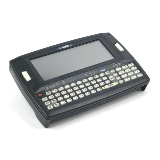
Page 7: The Mx3 Hand Held Computer
The keys on the keypad are constructed of a phosphorescent material that can easily be seen in dimly lighted areas. The MX3 is an MS-DOS compatible computer designed to run as a batch unit or run software applications such as LXE’s Terminal Emulator applications (ANSI Plus, LDS Plus, DOS 5250, DOS 3270, TN3270 and TN5250). -
Page 8: Components
11. Scanner LED 12. Backup Battery LED 13. Status LED 14. Main Battery LED 15. Charger LED 16. Scan or Enter Figure 1 Front of MX3 1. Endcap 2. Leather Handstrap Connector 3. IR Port 4. Cradle Input Contacts 5. Main Battery Figure 2 Back of MX3 MX3 Installation and Operator’s Guide... -
Page 9: Display
Lint/particulates can be removed with clean, filtered canned air. Optional Touch Screen A touch screen option is available that allows signature capture and touch input with the appropriate software load. A pen stylus is included with the touch screen option. Contact LXE for availability. E-EQ-MX3OGWW-D... -
Page 10: Display Backlight
The ability of touch screen activation to wake up the MX3 is configurable in BIOS Setup. Refer to the “MX3 Reference Guide” for details. -
Page 11: Panning
Columns 8x16 The MX3 display window can be panned up and down using keypress sequences so the user can view an entire virtual 640 x 480 pixel screen. Initially, using the default 8 x 16 pixel font, the top half (15 rows x 80 columns) of a 25 line virtual screen is displayed. -
Page 12: Endcaps
Read all cautions, warnings and labels before using the laser scanner. Figure 5 Scanner LED Location Dual Serial Port 1. DC Power jack 2. Dual Serial Port (COM 1 and COM 2) Figure 6 Dual Serial Port MX3 Installation and Operator’s Guide E-EQ-MX3OGWW-D... -
Page 13: Com Port Switching
IR Port COM Port Switching The default COM 2 port is always the IR port on the back of the MX3, regardless of the endcap installed on the MX3. On the Standard Range Scanner / Serial Port endcap COM 1 is the Integrated Scanner port. -
Page 14: The Keypads
The Keypads The Keypads There are two keypads and three overlays available for the MX3. All keypads are phosphorescent. A phosphorescent keypad does not use a keypad backlight but glows in dim/dark areas after exposure to a light source. All keypads are installed and configured by LXE. -
Page 15: The Overlays
There are four keypad overlays. One for the ABCD keypad and three for the QWERTY keypad. Figure 10 ABCD Keypad - ANSI/LDS/PC Overlay Figure 11 QWERTY Keypad - ANSI/LDS/PC Overlay Figure 12 TN3270/3270 Overlay for QWERTY Keypad Figure 13 TN5250/5250 Overlay for QWERTY Keypad E-EQ-MX3OGWW-D MX3 Installation and Operator’s Guide... -
Page 16: Programmable Buttons
Scan Field Exit w/ FLD EXIT label Serial/Serial Numeric keypad Enter Field Exit w/ FLD EXIT label Regardless of the type of endcap installed, the default value of the Right Button is always Scan. MX3 Installation and Operator’s Guide E-EQ-MX3OGWW-D... -
Page 17: Scan Key Function
The Keypads Scan Key Function (MX3’s with Scanner endcaps only.) The Scan key activates the scanner when a scanner endcap is installed and the Scan button is pressed. The internal scanner scans only when the Scan button is pressed. A Scan button press has no effect on externally attached scanners. -
Page 18: Shft Key Function
Reset Key Sequence Reset Key Sequence is Ctrl + Alt + 2nd + Dot. The Reset Key sequence can be disabled in the BIOS Setup. See the “MX3 Reference Guide”. DOS Key Functions Not Available on the MX3 Prnt Scrn A function that is available at the DOS prompt on a desktop PC. -
Page 19: Function Leds
The next letter is the uppercase letter on alpha keys and the shifted character on the numeric keypad keys. • Orange or unlit. CAPS Uppercase letters are active until the CAPS key sequence is pressed again. • Orange or unlit. E-EQ-MX3OGWW-D MX3 Installation and Operator’s Guide... - Page 20 - Main Battery is charging. • Green - battery charge is complete. • Yellow - Fault or Temperature Standby (contact LXE Customer Services). • Unlit - MX3 is not seated properly in the cradle. MX3 Installation and Operator’s Guide E-EQ-MX3OGWW-D...
-
Page 21: Power Button Functions
Figure 16 Location of the Power (PWR) Button The Power button is used to turn the MX3 on and off and force it into the Suspend state. The MX3 will beep when the power key is pressed and beep once every second the button is held down. -
Page 22: Power Status And The Status Led
Power Management and the Keypad Status LED is Steady Green. When the MX3 is in the Display Off state, any keypress or screen touch (if touch screen is installed) returns the computer to the On state and the display activates. -
Page 23: Cradles
MX3 and, in turn, the MX3 recharges the Main Battery. The MX3 can be either on or off while in the cradle. The MX3 can be inserted and removed from the cradle with one hand. -
Page 24: Status Led
LXE US AC Adapter or an LXE International AC Adapter. When powered, the cradle transfers power to the internal charging circuitry of the MX3 allowing it to recharge the Main Battery. A powered cradle supports RS-232 and IR communications. -
Page 25: Rs-232 Connector
RS-232 Connector Figure 21 Desktop Cradle RS-232 Connector The RS-232 connector is located on the back of the cradle. When the MX3 is properly docked, the bi-directional half-duplex transceivers in the MX3 and cradle are aligned through their IR windows. The half-duplex IR signals from the MX3 are converted to RS-232 signals in the cradle and available at this connector. -
Page 26: Vehicle Mount Cradle
The MX3 is removed from the cradle by pressing the release mechanisms and pulling the MX3 up and away from the cradle. -
Page 27: Power Connector
RS-232 Connector Figure 24 Vehicle Cradle RS-232 Connector The RS-232 connector is located on the back of the cradle. When the MX3 is properly docked, the bi-directional half-duplex transceivers in the MX3 and cradle are aligned through their IR windows. The half-duplex IR signals from the MX3 are converted to RS-232 signals in the cradle and available at this connector. -
Page 28: Getting Help
LXE website. Contact your LXE representative to obtain the LXE Manuals CD (Product No. 9000A426LXEMANUALS). You can also get help from LXE by calling the telephone numbers listed on the LXE Manuals CD, in the file titled “Contacting LXE”. This information is also available on the LXE website www.lxe.com. -
Page 29: Operation
Insert Main Battery Note: New batteries must be charged prior to first use. This process takes up to four hours in an LXE Multi-Charger and eight hours with an external power source attached to the MX3. 1. Front Side 2. Contacts, Main Battery 3. -
Page 30: Figure 26 Mx3 Battery Contacts
Insert Main Battery Figure 26 MX3 Battery Contacts The MX3 Battery Compartment is located at the bottom of the back of the computer. The arrows in the figure above point to the battery and cradle contacts in the computer. Figure 27 Main Battery Place the battery in the compartment, making sure the side of the battery with six contacts match up with the battery contacts in the computer battery compartment. -
Page 31: Attach Hand Strap (Optional)
3. Place the MX3, with the screen facing down, on a flat stable surface. 4. Attach the hand strap to the MX3 with the screws and washers provided. 5. Test the strap’s connection making sure the MX3 is securely connected to each end of the strap. -
Page 32: Power Supplies (Optional)
UL Listed, with LPS or Class 2 outputs rated 12V, minimum 1Amp. The MX3 DC power jack is located on the endcap. The cradle power jack is located on the back of the cradle. The MX3 (and the Desktop Cradle) connect to any of the following power supplies through the DC Power Jack. -
Page 33: Power On And Off
Hold the Power button down. The unit will emit three short beeps and one long beep. After the long beep the MX3 will power down. The Power button and the display will turn off. The Power key function is configured in the BIOS Setup (See the “MX3 Reference Guide”.) Note: Quickly tapping the Power button will place the MX3 in Suspend mode. -
Page 34: Adjust Display And Volume
The keypad is used to manually input data that is not collected otherwise. Almost any function that a full sized computer keyboard can provide is duplicated on the MX3 keypad but it may take a few more keystrokes to accomplish a keyed task. -
Page 35: Scanner Entry
Align the red beam so that the barcode is centered within the beam. The laser beam must cross the entire barcode. Move the MX3 towards or away from the barcode so that the barcode takes up approximately two-thirds the width of the beam. -
Page 36: Batteries
RF transmitter, the shorter the time required between battery recharges. The MX3 keeps date and time valid for a minimum of four days using a fully charged Backup Battery and a Main Battery that has reached the Low Warning point. -
Page 37: Critical Suspend State
Suspend state. To resume operation tap the Power key for one beep. If the Off Timer expires the MX3 will turn itself off and all unsaved information is lost. Insert a fully charged main battery and press the Power button to turn the MX3 back on. -
Page 38: Battery Chargers
Battery Chargers Optional LXE Multi-Charger Figure 34 MX3 Charger Analyzer The Main Battery can be charged in the LXE Multi-Charger. The Main Battery charges the Backup Battery. Figure 35 Insert Main Battery in Charger Insert the Main Battery into the Multi-Charger as shown above. The retaining clip will snap the battery into place in the charging cup. -
Page 39: Scanner Warnings And Labels
• Do not stare directly into the laser beam. • Do not remove the laser caution labels from the MX3. • Do not connect the laser barcode window to any other device. The laser barcode window is certified for use with the MX3 only. - Page 40 Scanner Warnings and Labels An EMS Technologies Company MX3 Installation and Operator’s Guide E-EQ-MX3OGWW-D...
-
Page 41: Appendixa Key Maps
Keypads Figure 38 ABCD Keypad and QWERTY Keypad The key maps that follow represent the commands used with batch units and when running LXE’s ANSI Plus (with either 900MHz or 2.4GHz radios) or LDS Plus (with 900MHz radios) Terminal Emulation (TE) programs. When running these programs on the MX3, please refer to the following terminal emulation reference guides for equivalent keys and keypress sequences: •... -
Page 42: Key Map 101-Key Equivalencies For Batch Units
Up Arrow Up Arrow Down Arrow Down Arrow Right Arrow Right Arrow Left Arrow Left Arrow Insert BkSp Delete Left Scan key default value is Numeric Enter. Right Scan key default value is Scan. MX3 Installation and Operator’s Guide E-EQ-MX3OGWW-D... - Page 43 Keypads Press These Keys and Then To get this Press this Shift Ctrl CapsLock Home Left Arrow Right Arrow Page Up Up Arrow Page Down Down Arrow Right Shift Right Alt Right Ctrl ScrollLock E-EQ-MX3OGWW-D MX3 Installation and Operator’s Guide...
- Page 44 Keypads Press These Keys and Then To get this Press this Shift Ctrl CapsLock 1 (alpha) 2 (alpha) 3 (alpha) 4 (alpha) 5 (alpha) 6 (alpha) 7 (alpha) 8 (alpha) MX3 Installation and Operator’s Guide E-EQ-MX3OGWW-D...
- Page 45 DOT (numeric) < > / (numeric) / (alpha) - (numeric) - (numeric) - (alpha) + (numeric) + (alpha) * (numeric) * (alpha) : (colon) ; (semicolon) _ (underscore) , (comma) ‘ (apostrophe) ~ (tilde) E-EQ-MX3OGWW-D MX3 Installation and Operator’s Guide...
- Page 46 Keypads Press These Keys and Then To get this Press this Shift Ctrl CapsLock “ & MX3 Installation and Operator’s Guide E-EQ-MX3OGWW-D...
-
Page 47: Ibm 3270 And Tn3270 Terminal Emulator Keypad
This keypad is designed to allow the user to enter terminal emulator commands when running LXE’s IBM 3270 and TN3270 Terminal Emulation (TE) programs. When running these programs on the MX3, please refer to the following terminal emulation reference guides for equivalent keys and keypress sequences: •... - Page 48 Keypads An EMS Technologies Company MX3 Installation and Operator’s Guide E-EQ-MX3OGWW-D...
-
Page 49: Appendixb Manuals And Accessories
MX3 SW Configured Without Radio MX3 SW Configured with 900MHz Radio MX3 SW Configured With 2.4GHz Radio (Type II or III) MX3 SW Configured With 2.4GHz Radio and TCP/IP (Type II or III) Terminal Emulation Software Packages: ANSI Plus for MX3 with 900MHz Radio ANSI Plus for MX3 with 2.4GHz Radio... -
Page 50: Accessories
Power Adapter, Bare Wire 12 VDC 1300A053CBL12ML3 Power Adapter, 24-72 VDC, 20 Watts 1300A301PS24WW Power Adapter, 110-240 VAC 1300A303PSACWW Cables for Cradle and MX3 Serial Ports Cable, Printer/PC, DA-9F to DB-25M, 6 ft. 9000A053CBL6D9D25 Cable, PC, DA-9F to DA-9F, 6 ft. 9000A054CBL6D9D9 Power Adapter Required. -
Page 51: Appendixc Regulatory Notices And Safety Information
UL. Li-Ion Battery When disposing of the MX3 Main Battery, the following precautions should be observed: The battery should be disposed of promptly. The battery should not be disassembled or crushed. The battery should not be heated above 212°F (100°C) or incinerated. - Page 52 Information to User A label on the exterior of the device should resemble one of the labels shown below (the label contains the LXE part number of the installed radio card). The labels shown below and affixed to the device, identify where the device may be used and where its use is restricted.
-
Page 53: Regulatory Notices And Safety Information
Safety of information technology equipment, including electrical business equipment + Amendments A1..A4 We, LXE Inc., declare that the equipment specified above complies with all Essential Health and Safety Requirements of the above Directives and Standards, as amended. Signed: Place: LXE Inc., Norcross GA USA... - Page 54 Safety of information technology equipment, including electrical business equipment + Amendments A1..A4 We, LXE Inc., declare that the equipment specified above complies with all Essential Health and Safety Requirements of the above Directives and Standards, as amended. Signed: Place: LXE Inc., Norcross GA USA R.
- Page 55 EN 60950-2: 1992 + A1..A4 Safety of information technology equipment, including electrical business equipment We, LXE Inc., declare that the equipment specified above complies with all Essential Health and Safety Requirements of the above Directives and Standards, as amended. Place LXE Inc., Norcross GA USA...
- Page 56 With regard to the use of external antennas The LXE 6726 can be equipped with external antennas. The antennas listed have been evaluated with the LXE 6726 pursuant to ETSI EN 300 328, and therefore meet the definition of ‘dedicated antenna’ per ERC/REC 70-03 Appendix 1 Table 3; thus the requirement set forth in ERC/REC 70-03 , Annex 3 are met by the LXE model 6726 transceiver.
- Page 57 EN60950-1: 2001 business equipment The product carries the CE Mark: We, LXE Inc., declare that the equipment specified above complies with all Essential Health and Safety Requirements of the above Directives and Standards, as amended. Date of issue: June 18, 2003 Cyril A.
- Page 58 With regard to the use of external antennas The LXE 6816 can be equipped with external antennas. The antennas listed have been assessed with the LXE 6816 pursuant to EN 300 328, and therefore meet the definition of ‘dedicated antenna’. The table below lists the maximum output power setting for the radio module in order to result in a total EIRP of 100mW or less.
- Page 59 Regulatory Notices and Safety Information A/C Power Supply Safety Statement – MX3 Output Rated 12 VDC, 1 A. Optional A/C Power Supply: Outside North America, this unit is intended for use with an IEC certified ITE power supply with output rated as stated at the top of this page.
-
Page 60: Laser Light Safety Statement
Este producto usa luz de láser. Las etiquetas se proveen en la máquina exploradora. Por favor, lea detenidamente la explicación para las precauciones. (ES) Waarschuwing: Dit product gebruikt laserlicht. Een van de volgende labels is op de scanner aangebracht. Lees a.u.b. de waarschuwing onder Oppassen. (NL) MX3 Installation and Operator’s Guide E-EQ-MX3OGWW-D... - Page 61 üstünde saðlanýr. Lütfen Dikkat ifadesini okuyun. (TR) (GR) (JP) (KR) Legend: Chinese-CN; Danish-DK; Dutch-NL; English-US; Finnish- FI; French-FR; German-DE; Greek-GR; Italian-IT; Japanese-JP; Korean-KR; Norwegian-NO; Portuguese-PT; Spanish-ES; Swedish-SE; Turkish-TR (CN) Labels - MX3 Hand Held Computer E-EQ-MX3OGWW-D MX3 Installation and Operator’s Guide...
- Page 62 Regulatory Notices and Safety Information An EMS Technologies Company MX3 Installation and Operator’s Guide E-EQ-MX3OGWW-D...
-
Page 63: Index
Scan Key ............11 what happens when ........... 34 Shft Key ............12 Critical Suspend state ..........34 Spc Key............. 12 Ctrl key function............ 11 Handstrap, How To ..........27 Data entry, How To ..........30 E-EQ-MX3OGWW-D MX3 Installation and Operator’s Guide... - Page 64 Main Battery Low Warning........16 Status/Notification LED ........16 Main Battery Power Failure ......16, 34 Suspend States ............15 Manuals ..............47 Suspend Timer............15 Mode Key Functions ..........12 MX3 Reference Guide..........1 MX3 Installation and Operator’s Guide E-EQ-MX3OGWW-D...
- Page 65 Touch Screen ............3 Volume adjust beeper volume ........30 Unavailable DOS key functions..........12 Wake the MX3 from Suspend ....... 15 Wake Up..............16 Wake up action for display backlight ...... 4 Warnings and Labels Vehicle cradle Laser Scanner............ 37 E-EQ-MX3OGWW-D MX3 Installation and Operator’s Guide...
- Page 66 Index An EMS Technologies Company MX3 Installation and Operator’s Guide E-EQ-MX3OGWW-D...
Need help?
Do you have a question about the MX3 and is the answer not in the manual?
Questions and answers