
Related Manuals for SNBC BTP-2002NP


Summary of Contents for SNBC BTP-2002NP
-
Page 1: Service Manual
CONFIDENTIAL SERVICE MANUAL Receipt Printer BTP-2002NP Shandong New Beiyang Information Technology Co., Ltd. - Page 2 Confidential BTP-2002NP Service Manual Revision Sheet Date Version No. Description Distributor Mr. Peng Yuan Bin Mr. Yang Min 2006-10-18 V1.0 Release Mr. Xu Jia Bo Mr. Zhang Tao 2007-04-25 V2.0 Revision V2.0 Mr. Yang Min 2007-06-30 V2.01 Revision V2.01 Mr. Yang Min 2007-12-05 V2.02...
- Page 3 Confidential BTP-2002NP Service Manual Declaration Information in this document is subject to change without notice. SHANDONG NEW BEIYANG INFORMATION TECHNOLOGY CO., LTD. (hereinafter referred to as “SNBC”) reserves the right to improve products as new technology, components, software, and firmware become available. If users need further data about this product or have any doubt about safety issues that might arise from using it, please feel free to contact SNBC or your local agents.
- Page 4 Confidential BTP-2002NP Service Manual BTP-2002NP has been approved of the following certification. Contact us Address: No.169 Huoju Rd, Weihai, Shandong, China. 264209 Hot line: +86-631-5673777 Fax: +86-631-5673778 E-mail: sales@newbeiyang.com - 3 -...
- Page 5 Confidential BTP-2002NP Service Manual Notes Follow the steps in this manual hereafter during maintenance. Make sure that the printer and the computer are turned off before pluging the communication cable, changing print head or doing maintenance to the printer. Be sure to protect it against electrostatic damage when maintaining print head and other electronics.
-
Page 6: Table Of Contents
Confidential BTP-2002NP Service Manual Contents 1 FEATURES AND SPECIFICATIONS ................1 1.1 F ................................1 EATURES 1.2 S ..............................1 PECIFICATIONS 2 PRINTER OVERVIEW....................... 2 3 MAIN CONTROL BOARD UNIT BLOCK DIAGRAM ............3 4 DISASSEMBLY AND ASSEMBLY ..................5 4.1 M ............................5... - Page 7 Confidential BTP-2002NP Service Manual 6.4 A ..............................17 UTTER 6.5 C ..............................17 RAWER 6.6 S ................................18 ENSORS 6.7 LED/KEY .............................18 UZZER APPENDIX ......................... 19 A: M ....................19 PPENDIX ONTROLL OARD ESCRIPTION B: H .........................27 PPENDIX EXADECIMAL C: C ........................28 PPENDIX ONTROL...
-
Page 8: Features And Specifications
BTP-2002NP Service Manual 1 Features and Specifications 1.1 Features The BTP-2002NP is a high performance thermal printer. It can be widely used for real-time printing applications, such as for POS systems, hospitality, ATM, etc. Low noise and high printing speed. -
Page 9: Printer Overview
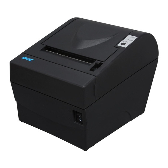
Confidential BTP-2002NP Service Manual 2 Printer Overview This printer is made up of the following major components: BTP-2002NP Printer Mechanism (Sensor and LED/KEY switch circuit board assembly) Interface board assembly Main Control board - 2 -... -
Page 10: Main Control Board Unit Block Diagram
Confidential BTP-2002NP Service Manual 3 Main Control Board Unit Block Diagram The block diagram of various components and main control board is shown below. Block diagram The top side of main control board - 3 -... - Page 11 Confidential BTP-2002NP Service Manual The bottom side of main control board Position of each connector - 4 -...
-
Page 12: Disassembly And Assembly
Confidential BTP-2002NP Service Manual 4 Disassembly and Assembly Cautions: Do not disassemble, assemble or adjust the printer if it works properly. Do not loosen any screw unless necessary. When disassembling and assembling, avoid all wires and cables form damages. Do not let them pass by a narrow space or place them in improper position. -
Page 13: Disassemble The Printer
Confidential BTP-2002NP Service Manual 4.2 Disassemble the Printer Disassembly steps are shown as below: 4.2.1 Remove the Main Control Board Pictures Instructions Top view of printer. Remove the two screws. Pull out the main control board module slantways for a certain distance in the direction. -
Page 14: Disassemble The Main Control Board And The Interface Board
Confidential BTP-2002NP Service Manual 4.2.2 Disassemble the Main Control Board and the Interface Board Pictures Instructions Remove the two screws of the interface metal plate. Pull out the interface board. Remove the four screws on the control board (M3x4) and take out the main control board. -
Page 15: Disassemble Printer Top Cover And Cutter Cover
Confidential BTP-2002NP Service Manual 4.2.3 Disassemble Printer Top Cover and Cutter Cover Pictures Instructions Remove the two screws. Remove the printer top cover. Picture of the opened top part of the mechanism. 4.2.4 Disassemble Cutter Cover Pictures Instructions Hold the cutter cover at the position as shown. -
Page 16: Disassemble The Top Housing And The Feed Button/ Led Module
Confidential BTP-2002NP Service Manual 4.2.5 Disassemble the Top Housing and the Feed button/ LED Module Pictures Instructions Remove the two screws. Take off the upper cover in the direction as shown. Remove the two screws. Picture of Feed button/ LED Module 4.2.6 Disassemble the Printer Mechanism... -
Page 17: Disassemble The Platen Roller
Confidential BTP-2002NP Service Manual 4.2.7 Disassemble the Platen Roller Pictures Instructions Remove the platen gear. 1. Remove the e-ring with screw driver (line type). 2. Remove the platen bushing. 1. Remove the e-ring with screw driver (line type). 2. Remove the platen bushing. -
Page 18: Disassemble The Motor
Confidential BTP-2002NP Service Manual 4.2.9 Disassemble the Motor Pictures Instructions Cut off the clip with wire clamp pliers. Remove the two screws. Take off the motor. 4.2.10 Disassemble the Micro Switch Pictures Instructions Remove the two screws. Take off the Micro-switch. -
Page 19: Disassemble The Print Head Module And Spring Pressing Plate
Confidential BTP-2002NP Service Manual 4.2.11 Disassemble the Print head Module and Spring Pressing Plate Pictures Instructions Push the spring pressing plate along the indication of the arrow. Remove the spring pressing plate and the springs. Take off the print head module. -
Page 20: Disassemble The Paper Near End Sensor
Confidential BTP-2002NP Service Manual 4.2.13 Disassemble the Paper Near End Sensor Pictures Instructions Remove the four screws. Take off the paper near-end sensor modules. 4.2.14 Disassemble the Power Switch Pictures Instructions Cut off the clip with wire clamp pliers. Remove the glue with a screw driver (line type). -
Page 21: Disassemble The Paper End Sensor Module
Confidential BTP-2002NP Service Manual 4.2.15 Disassemble the Paper End Sensor Module Pictures Instructions Remove the two screws, take off the paper cabinet module. Remove the two screws and take off the paper end (or marked) sensor module. 4.3 Assembly To assemble, please reverse the disassemble procedure in accordance with the instructions given. -
Page 22: Error Types And Processing
Confidential BTP-2002NP Service Manual 5 Error Types and Processing Errors that can be automatically recovered ERROR LED Blinking Pattern Buzzer sound Error Description Recovery 200ms 200ms Print head The temperature of Recovers automatically temperature the print head is when the print head cools... -
Page 23: Troubleshooting Guide
Confidential BTP-2002NP Service Manual 6 Troubleshooting Guide The following descriptions help you to locate the possible causes of problems. Please check and operate according to check method and solution. 6.1 Power Supply Problems Possible Causes Check Method Solution Connection of the power adapter is not... -
Page 24: Paper Feeding
Confidential BTP-2002NP Service Manual 6.3 Paper Feeding Problems Possible Causes Check Method Solution Incorrect paper feeding Check whether or not the paper Remove the jammed paper and operation jams load the paper correctly Connection of the motor cable Connect the cable reliably... -
Page 25: Sensors
Confidential BTP-2002NP Service Manual 6.6 Sensors Problems Possible Causes Check Method Solution Connection of the sensor cable is Connect the cable reliably not reliable The cable or connector of sensor is Replace the cable or connector abnormal Paper can not... -
Page 26: Appendix
The CPU and CPU Peripheral Logic circuits are made up of the following electrical circuits: CPU, RAM, FLASH, reset circuit. The CPU (U101) of the BTP-2002NP printer works with 3.3V supply voltage and 40.5MHZ external clock. Its reset pulse should be active low and the reset pulse length should be no less than 400ms. - Page 27 Thermal Head Drive Circuit The print head of the BTP-2002NP printer is a thermal type print head with 640 dots per line. All print head control is performed via a gate array. A driver is built into the print head. CPU sends the print data by signal TPHDAT, which is synchronized with the TPHCLK signal, to the driver sets the print/non-print status of each dot.
- Page 28 Confidential BTP-2002NP Service Manual Motor Drive Circuit The paper feed motor of the printer is a step motor. The motor drive uses a special purpose motor IC (U402). By the signals (I01, I11, PHASE1, I02, I12, PHASE2), CPU can control paper feed motor.
- Page 29 The detector circuits are made up of the following circuits: Paper end sensor circuit The BTP-2002NP printer is equipped with a paper end sensor, which is connected via switch circuit board assembly to the main control board. Paper end signal PAPER is input to the CPU’s analog port (PIN 77).
- Page 30 Q301 to turn on, which turn on the buzzer. Signal BUZ-CTL is connected to CPU pin (PIN72). Interface Board Assembly The BTP-2002NP printer can be connected to the host computer with a variety of different interfaces by changing the interface board. The board types are below: RS-232 Interface...
- Page 31 Confidential BTP-2002NP Service Manual Signal definition number Signal name Signal direction Function — Frame ground Output Transmit data Input Receive data Output Same as DTR signal This signal indicates whether or not the host computer Input can receive data. —...
- Page 32 Confidential BTP-2002NP Service Manual Signal definition Pin Number Source Compatible nStrobe Data 0 (Least Significant Bit) Data 1 Data 2 Data 3 Data 4 Data 5 Data 6 Data 7 (Most Significant Bit) nAck Busy Perror Select nAutoFd Not defined...
- Page 33 Confidential BTP-2002NP Service Manual Data Receiving Timing (Compatibility Mode) USB Interface Specifications Data transmission: Universal Serial Bus Specification Revision 1.1 Connector (printer side): USB “B” type connector (standard) Signal definition Pin Number Signal Name Function VBUS DATA- Printer data transmit line minus...
-
Page 34: Appendix B: Hexadecimal Dump
Confidential BTP-2002NP Service Manual Appendix B: Hexadecimal Dump This feature allows experienced users to see exactly what data is coming to the printer. This can be useful in finding software problems. When you turn on the hex dump function, the printer prints all commands and other data in hexadecimal format along with a guide section to help you find specific commands. -
Page 35: Appendix C: Control Sequences
Confidential BTP-2002NP Service Manual Appendix C: Control Sequences The control sequences of the printer controller are POS compatible Code Function Horizontal tab Print and line feed Print and return to standard mode (in page mode) Print and carriage return Cancel print data in page mode... - Page 36 Confidential BTP-2002NP Service Manual FS q 1C 71 28 113 Define NV bit image GS ! 1D 21 29 33 Select character size GS $ 1D 24 29 36 Set absolute vertical print position in page mode GS * 1D 2A...
-
Page 37: Appendix D: Eeprom Setting Table
Confidential BTP-2002NP Service Manual Appendix D: EEPROM Setting Table EEPROM Address Default Value Function Description (0xAD) (0xDL) Print darkness 0x02 0x6e [Range]=1-120 Unit=mm/s Print speed 0x06 0x96 In normal mode, the speed will be 200mm/s In low power mode, the speed will be 150mm/s... -
Page 38: Appendix E: Service Parts List
Confidential BTP-2002NP Service Manual Appendix E: Service Parts List Service part list Parts Part No. Reference Picture TPH head 3000-903314 TPH cable 7110-900369 7600-900838 Paper sensor module Platen roller 8301-900171 Step motor 3200-900260 Micro switch module 7600-900837 Latch Paper near end... - Page 39 Confidential BTP-2002NP Service Manual Gear 2 8203- 900086 (Middle size) Transmission gear 8203- 900087 (Largest) Auto cutter module 3100- 900688 Include stationary blade Main control board 7201-903818 7600-900840 White Power switch 7600-900841 Black Feed button and LED module 7600-900521 Rubber foot...
- Page 40 Confidential BTP-2002NP Service Manual Parts List for Mechanism Ref. No. Parts No. Description Quantity Remarks 8201-900077 Printer top cover 8201-900073 Top case 4006-900295 M3X5 screw 8201-900075 Cutter cover 4002-900301 ST2.6X6 screw GB845-85 7600-900521 Operator’s control panel PCB 4002-900291 ST2.6X4screw GB845-85...
- Page 41 Confidential BTP-2002NP Service Manual 8005-900919 Stretch plate 8103-900132 Top cover stand 2 8104-900119 Tear bar 3100-900688 Cutter 8103-900131 Top cover stand 1 3100-900688 M2.6X6 3000-900848 Print head 8005-901368 Print head pressure spring 8103-900091 Print head protection plate1 8103-900136 Print head protection plate2...
-
Page 42: Appendix F: Printer Exploded View
Confidential BTP-2002NP Service Manual Appendix F: Printer Exploded View Exploded View 1 Exploded view 2 - 35 -... -
Page 43: Appendix G: Outline Drawing
Confidential BTP-2002NP Service Manual Appendix G: Outline Drawing - 36 -...
Need help?
Do you have a question about the BTP-2002NP and is the answer not in the manual?
Questions and answers