Table of Contents
Advertisement
Quick Links
Advertisement
Table of Contents

Related Manuals for Gatekeeper YG-5602

Summary of Contents for Gatekeeper YG-5602
- Page 1 YG-5602/1U/E Swinging Gate Owner’s Manual...
- Page 2 YG-5602/1U/E Swinging Gate Owner’s Manual, Version 4 ©2014 Gatekeeper Ltd. P.O. Box 752 Lacey’s Spring, AL 35754 www.gatekeeperltd.com Latest version available at www.gatekeeperltd.com/YG5602UE_User_Manual.pdf page 2...
-
Page 3: Table Of Contents
Table of Contents Gatekeeper YG Featuress ....................5 Construction ....................... 5 Power ......................... 5 Locks/Security......................6 Operation ........................6 Installation Guide Safety Precautions ......................8 Pre-installation ........................ 9 Gates ........................... 9 Conduit ........................9 Permits ........................9 Power Requirements ....................10 Standard Power ...................... - Page 4 Auto-close function (DIP Switch 4 & 5) ..............32 Additional Features ....................33 Maintenance Guide Mechanical Maintenance ....................36 Symptoms/Solutions...................... 36 Gatekeeper Specifications ..................... 38 Gate Arm Actuator Parts ....................39 Actuator Specifications and Measurements..............40 Gatekeeper Ltd. Limited Warranty ................41 page 4...
-
Page 5: Gatekeeper Yg Featuress
Each arm supports a gate leaf that weighs up to 600 lbs. or 12 feet in length. When used on two gates, the Gatekeeper YG opens up to 24 feet of gates weighing up to 1,200 pounds. -
Page 6: Locks/Security
Locks/Security Keypad interface Single button interface Infrared safety beam interface Supports up to 15 remotes (two included). Rolling RF Codes (theft deterrent) Solid steel lock included Emergency manual key release Operation Adjustable output thrust ... -
Page 7: Installation Guide
YG-5602/1U/E Swinging Gate Installation Guide page 7... -
Page 8: Safety Precautions
Safety Precautions Please read the following as common-sense reminders for the installation and use of the Gatekeeper YG. This is an electrical/mechanical device that can cause injury or death! Installing the YG-5602/1 Gate Opener requires standard 110V or 230V electrical wiring. -
Page 9: Pre-Installation
Gatekeeper YG. Gates Each Gatekeeper YG actuator will handle a gate weight up to 661 lb. (300Kg) and a length of 12 ft. (3.6 m). Verify that your gates do not exceed these limits. -
Page 10: Power Requirements
The Gatekeeper YG requires at least 15A service. Make sure your electrician takes into account the voltage drop involved in running the wire to your installation location. Use a sufficient gauge wire to accommodate initial voltage and voltage at the gate. -
Page 11: Inside The Box
The shipping box you received from Gatekeeper Ltd. contains the retail packaging for the Gatekeeper YG. Open the box and carefully remove the items. Place the items on trays or a tarp so that you can verify the contents. Mark each item opened as “Received.”... - Page 12 Qty Rcd Item Antenna Key Switch Button Switch RF Opener Fobs Set of Two Keys Bracket Assembly T Bracket L Bar Z Bracket Cotter Pins/Cotter Pin Bolts Antenna Plate Mounting Screws page 12...
- Page 13 If you are missing something, please check the box and the packaging materials carefully. Some of these items are small and can be easily lost. If you are definitely missing parts, please contact Gatekeeper Ltd. immediately by sending an email to support@gatekeeperltd.com or calling your respective support line: in the US (844) 526-5881, or in the UK 238-003-9023.
-
Page 14: Pre-Installation Checklist
You have all required permits. You have verified the contents of the shipping box. If any remediation is required, do so before you begin installing the Gatekeeper YG. If you have any questions, please email support@gatekeeperltd.com or call your respective support line: in the US (844) 526-5881, or in the UK 238-003-9023. -
Page 15: Installation
Installation The actual installation of the Gatekeeper YG will take about four hours, if all goes well. Completing the “Pre-installation Checklist’ will expedite the installation process. Ensure you have sufficient time so you can complete the installation once you begin. -
Page 16: Pull To Open Inward
Pull to Open Inward This configuration pulls your gate open, into your property, to open. Mount the actuators on the included brackets according to the figure below. The gate mounts on one face of the mounting post, and the opener mounts on the face 90 degrees from it. -
Page 17: Push To Open Outward
Push to Open Outward This configuration pushes the gate outward, away from your property, to open. Mount the actuators on the included brackets according to the figure below. The gate mounts on one face of the mounting post, and the opener mounts on the face 90 degrees from it. -
Page 18: Stopper And Latch Installation
Stopper and Latch Installation The stoppers act as limits for the gate movement. Installing the stoppers allows you to control exactly where your gate stops. The electric latch is added to hold the gate more securely than relying on the actuators to hold the gate closed. -
Page 19: Electric Lock Cross Section
Electric Lock Cross Section The following illustrates the electric latch assembly as a cross section. Weld the L Bar and electric lock to the gate for the most secure closure. The L Bar controls the offset of the gate leaf from the Gate Stopper. The Electric Lock attaches to the slave gate and contacts the Stop Block. -
Page 20: Electrical Installation
Electrical Installation Control Box Diagram This diagram illustrates the inner works of the control box and is included for your information. Connecting the AC Power The Control Box must have a single-phase circuit breaker (15A) between the Control Box and the power source. CAUTION! Be sure that the rocker switch on the bottom of the Control Box is in the “Off”... -
Page 21: Wiring The Battery
CAUTION! Make sure that the power is OFF at the source and is not connected to the Control Box before making any electrical connections. BEWARE! The battery is not secured when the Control Box is open. Open the box carefully so the battery does not fall out, damaging the unit or your foot. -
Page 22: Advanced Control Wiring
Advanced Control Wiring This picture details the Control Board. It identifies each of the items you will need during the installation of the Gatekeeper YG. The jumper numbers on the main board are named to help illustrate the connections that will be made. - Page 23 J1 – 1 & 2 MM1 Master Gate J2 – 3 & 4 SM2 Slave Gate J3 – 5 & 6 Electric Lock, 12VDC, maximum current 5A J3 – 7 & 8 Flashing Light, 12VDC, maximum power 21W J4 - 9 Positive Supply 12V DC J4 –...
- Page 24 MM1 Terminal block 1 & 2 Connect the cable to the MM1 for the master gate. (In gate opening operation, the master gate should be opened first) Important: connect only this interface if only using the single gate. SM2 Terminal block 3 & 4 Connect the cable to the MM2 for the slave gate.
-
Page 25: Wiring The Actuators
After the LED light turns off, the receiver module goes back to “Normal” mode. The Gatekeeper YG supports up to 15 remote controls. Repeat the RF Remote Learning Mode for each additional remote. -
Page 26: First Time Activation
If it is interrupted, you must restart the process from the beginning. If the Gatekeeper YG loses both power and backup battery power, anything stored in the memory will be lost. You will need to repeat the “System Self Learning Process.”... -
Page 27: Two Gate Operation
of the Control Board, will begin flashing quickly. After about 75 seconds, the gate will begin moving on its own as it begins learning its travel path. The learning mode executes as follows: 1. Master Gate Closes (actuator extends) 2. Master Gate Opens (actuator retracts) 3. -
Page 28: Flashing Light Codes
External Interfaces Keypad/ Button Switch/Key Switch The Gatekeeper YG is equipped with an interface for an external switch or keypad. The interface type is a NO (Normally Open) momentary switch to ground. This spring-loaded switch is normally open when the springs are relaxed and closes when the switch is forced to its other position. -
Page 29: Loop Detector
The device is usually buried in the driveway, under the point that you want the Gatekeeper YG to detect a vehicle. The wires are buried and run to the fence line then wired into the Control Board in the 9 – 15 IJ4) Additional Functions area. -
Page 30: Safeguards
Safeguards Infrared Photocell Device Included with your Gatekeeper YG is an Infrared (IR) Photocell Device. We strongly recommend that you install the infrared photocell to provide for additional safety for users of your gate. Photocells prevent the gate from moving if the IR beam is broken. -
Page 31: Auto-Reverse Function
Additional devices can be obtained through your dealer. To find a dealer, go to www.gatekeeperltd.com/dealers. Auto-reverse Function You must tune the safety reverse function after you have installed the Gatekeeper YG, performed all self-learning functions, and programmed any remote controls. The Control Box must be powered to tune the safety reverse. -
Page 32: Dip Switches
The auto-reverse function should be regularly inspected and adjusted if necessary. Once this step is complete, replace the cover and install the rubber caps over the screws. (VR1) Over-current Sensitivity: The range of Over-Current resistance can be adjusted between 3.5 amperes and 7 amperes by turning the screw. -
Page 33: Additional Features
Additional Features LIGHT DELAY: Flashing light delay on or off. ON: The flashing light starts 5 seconds ahead of gate moving. OFF: The flashing light starts and gate starts moving at same time. OPENING PHOTO: When the gate is moving at opening phase, the photo sensor can be selected as active or inactive. - Page 34 This page intentionally left blank. page 34...
-
Page 35: Maintenance Guide
YG-5602/1U/E Swinging Gate Maintenance Guide page 35... -
Page 36: Mechanical Maintenance
Mechanical Maintenance Regularly verify that the gate swings freely. The Gatekeeper YG rarely requires lubrication. Check that all wiring and electrical parts are weatherproof. Keep opener clean at all times. Inspect the auto-reverse function and adjust if necessary. - Page 37 ~12V DC is present when it is not plugged into AC but after charging. For additional information or assistance, contact the 24-hour customer support line: email: support@gatekeeperltd.com phone: US (844) 526-5881 or UK 238-003-9023. Additional information and helpful videos are available on the Gatekeeper website: www.gatekeeperltd.com/support page 37...
-
Page 38: Gatekeeper Specifications
Gatekeeper YG Specifications U Model 110V AC (60Hz) Power Supply E Model 230V AC (50Hz) Backup Battery: 12VDC / 4AH Maximum Number of Remote Controls 15 (2 Included) Maximum Gate Weight 300 KG / 661 lbs. Maximum Gate Width 3.6 meters / 12 feet per leaf... -
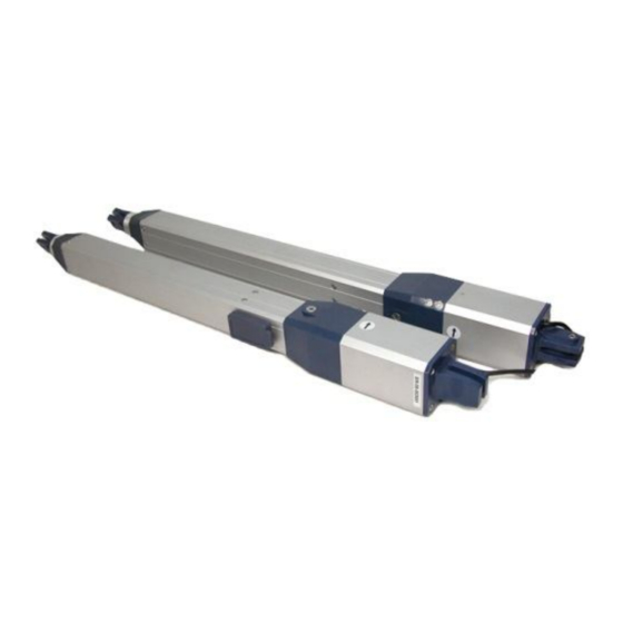
Page 39: Gate Arm Actuator Parts
Gate Arm Actuator Parts You need the following parts to connect an actuator to your gate. Quantity Description Single Dual Actuator Nest Pin Fastener Screw “L” Mounting Bracket Bar Mounting Bracket Nut for Bolt Bolt Release Key Bolt Cotter Pin “T”... -
Page 40: Actuator Specifications And Measurements
Actuator Specifications and Measurements Actuator Maximum Direct Force: 1400N , 315 lbs. Actuator Maximum Power Consumption: 12V at 6A = 72W Duty Cycle: 50% page 40... -
Page 41: Gatekeeper Ltd. Limited Warranty
We do not accept responsibility for damage or injury resulting from the installation of this opener. In no event shall Gatekeeper Ltd. be held liable for direct, indirect, incidental, special or consequential damages or loss of profits whether based on contract, tort, or any other legal theory during the course of the warranty or at any time thereafter. - Page 42 Gatekeeper Ltd. P.O. Box 752 Lacey’s Spring, AL 35754 info@gatekeeperltd.com For updated versions of the manual see: www.gatekeeperltd.com/YG5602UE_User_Manual.pdf For Additional Remotes, Infrared Photo Cells, or parts please contact your dealer: www.gatekeeperltd.com/dealers ©2005-2014 - Gatekeeper Ltd - All Rights Reserved...
Need help?
Do you have a question about the YG-5602 and is the answer not in the manual?
Questions and answers
Do you have a video for installation