GRAUPNER Polaron Operating Instructions Manual
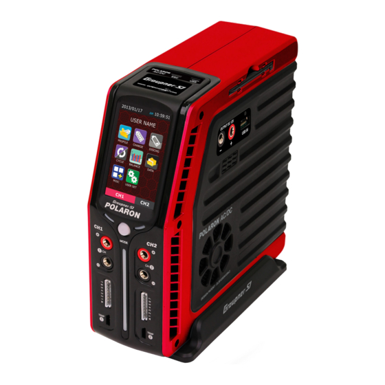
2 channels ac/dc charger
Hide thumbs
Also See for Polaron:
- Operating manual (18 pages) ,
- Operating instructions manual (6 pages)

Related Manuals for GRAUPNER Polaron


Summary of Contents for GRAUPNER Polaron
- Page 1 No. S2002 2 Channels AC/DC Charger OPERATING INSTRUCTION Pease read this manual thoroughly. Keep this manual in a convenient place for quick and easy reference.
-
Page 2: Table Of Contents
3245 University Ave, Suite 1520, San Diego, CA 92104, United States of America DATA INITIALIZATION Phone: +1 855-5-RCisHoTT ( +1 855-572-4746) Fax: +1 855-546-0350 TOUCH CALIBRATION E-mail: service@openhobby.com RESOURCE UPGRADE BLC PORT TEST ©2014 Graupner/SJ USA – OPENHOBBY LLC. The HoTT trademark is used with permission of SJ Inc. 4386066... -
Page 3: Box Contents
- If possible, place the battery in a safety bag during the charging or discharging process. ◎ BOX CONTENTS - Pay attention to the charger during use. Do not leave the charger unattended. - If the charger becomes hot, disconnect the battery and remove the input power immediately. 1. -
Page 4: Specifications
USB 5V output (5.0V 1.0A ) / USB B-Type Motor Test, Warmer, ESC setting Sub Function Firmware upgrade External Mini USB device PC communication Graupner/SJ Logging Software Languages Optional ( Basically English) 50x50x10mm x 2ea Dynamic Cooling Fan Cooling system Ext. Module socket... -
Page 5: Charger Control Identification
◎ CHARGER CONTROL IDENTIFICATION BACK FRONT RIGHT ⑦ ⑭ ⑧ ⑮ ③ ⑨ ④ ⑩ ① ⑪ ⑤ ② ⑥ ⑫ ⑬ ⑧ LED Indicator for Charge / Discharge ⑨ Channel Selection Button (CH1/CH2) ① ESC Configure Socket ② Mini USB ③... -
Page 6: Menu Configuration
◎ BATTERY CONNECTION page. This data can be programmed during the USER SET POLARON AC/DC chargers have two sets of outputs on the front of the charger. Channel 1 is on the left. process. Channel 2 is on the right. Each channel has two 4mm banana sockets with a 7 cell balance port and a temperature sensor input port. -
Page 7: Display
Display ◎ CHARGE PAGE To access the charge mode, tap the CHARGE icon on the main page. The parameters in this mode Memory number & Battery name are dependant on the selected battery type that was set on the profile page. Section 1 Battery type Battery Cell quantity and Voltage... -
Page 8: Nicd/ Nimh Battery Charge Setup
- Cut-Temp : Cut-off temperature. Detected using an optional temperature sensor, a safety cut-off The programmed data are stored in the memory and used to charge the batteries. Tapping the Enter temperature can be set to automatically terminate charging or discharging processes. This button initiates the charging process. - Page 9 [ NORMAL ] Charge modes for the POLARON AC/DC CHARGER NiCd/NiMH : The charger will charge the pack with a preset charge current, stopping the charging pro- LiPo, LiIon, LiFe CC-CV : Normal charge. FAST : Fast charge. cess every minute to calculate the voltage and detect the Delta peak. This process allows for improved N-STORE : Normal store charge.
-
Page 10: Discharge Page
This page (left) shows the charging process with the parameters ◎ DISCHARGE PAGE and graph. Both the voltage and current will increase to the preset parameters. The preset current may be limited by the charge/dis- Tapping the DISCHARGE icon on the main page will access the discharge mode. The pro- charge capacity and the input voltage setup. -
Page 11: Lipo, Lilon, Life, Nicd, Nimh, Batteries Discharge Processes
The charger will discharge the pack, stopping once after 3 minutes to calculate the internal resistance. programming, the charger will display a 5-second countdown. The discharging sequence is shown below. Discharge mode for the POLARON AC/DC CHARGER LiPo, Lilon, LiFe, NiCd, NiMH battery discharge processes LiPo, LiIon, LiFe NORMAL : Normal discharge. -
Page 12: Cycle Page
This page (left) shows a display of the discharging pro- USER NAME cess with the parameters and graph. Both the voltage and current will increase to the preset parameters. The pre- set current value may be limited by the charge/discharge Tap the CYCLE icon on the main capacity and the input voltage setup. -
Page 13: Cycle Operation Mode Per Battery Type
The preset current may be limited by the charge/discharge capacity and ithe nput voltage setup. The max charging process at 120W with a max discharging process at 30W. Cycle charge discharge mode of the POLARON AC/DC Charger LiPo, LiIon, LiFe, Pb CC-CV... -
Page 14: Balance Page
Center voltage Range voltage Pressing the button will cause the pop-up window to appear, asking for a confimation that you want to stop the operation. Tapping either the STOP or ESC button will cause the charger to either stop or continue the cycle, respectively. -
Page 15: User Setup Page
Finish Sound : 10 types of sounds are available. Cycle number Sound Time : The times available for the charger are Discharge time Charge time ON, OFF, 5sec, 15sec, and 1min. Beep : This parameter can be turned on/off to select Average voltage Peak voltage either an internal or an external button. -
Page 16: Misc Page (Addition Function)
1) BREAK-IN ◎ MISC PAGE (Addition function) - The motor is operated and limited by the preset voltage for the preset time. Tap the MISC icon on the main page to access the MISC mode and to program the Brushed power motor, Warmer and ESC functions. -
Page 17: Warmer Setup
1) BAT TERY WARMER 3) MOTOR TEST - At low temperatures, lithium type batteries tend not to perform well. This function is used - For the motor operations (6 steps), the average current (Aa) and the peak to warm up the batteries to ensure proper function for batteries stored outdoors. Connect the current (Ap) can be selected, using either 4.8V or 7.2V. - Page 18 2) TIRE WARMER - CAUTION - - This feature can be used to warm rubber tires, providing an important competitive edge on the · Depending on the version of the Air ESC, the throttle stick should be in the low-position. track.
-
Page 19: Factory Setup And Screen Calibration
Initialization has completed, the return to the Start up page will proceed automatically. Button for Channel changing and initializing < Factory Setting > Smart BMS *POLARON* 1. Data Initialization Touch calibration (Touch screen calibration) 2. Touch Calibr ation 3. Resource Upgr ade 4. -
Page 20: Resource Upgrade
◎ ERROR MESSAGES RESOURCE UPGRADE <Image & Sound> Press the button. POLARON AC/DC chargers have a number of error and ‘Download Start ’ warning messages that are designed to advise the user of any problems. Tapping the error message can clear the <... - Page 21 Low Output-Volt BLC Volt Low Output voltage is lower Balancer cell voltage is ◆ A Low Output-Volt error message indicates that than the selected cells too low ! ◆ A BLC Volt Low error message indicates that either the voltage setup is below the requirements for or voltages.
-
Page 22: Common Problems And Precautions For The Polaron Ac/Dc Charger
◎ NiCd, NiMH BATTERY SAFETY ◎ COMMON PROBLEMS AND PRECAUTIONS FOR THE POLARON AC/DC CHARGER - The charger has been turned on, but the LCD Screen is off. - With charging new NiCd/ NiMH batteries for the first time, the process may terminate . -
Page 23: The Guide For The Related Countries'certifications
- If Lithium Polymer battery packs are short-circuited or severely over-charged, elemental Lithium may be Product : POLARON AC/DC CHARGER deposited internally. If the battery pouch is damaged, elemental Lithium can escape from inside the HU071411-13003A battery. -
Page 24: Environmental Protection Notes
For more information about where you can drop off your waste equipment for recycling, please contact your local city office, your household waste disposal service or where you purchased the produce www.graupner-sj.com www.openhobby.com...