
Related Manuals for GRAUPNER POLARON AC/DC SPORTS


Summary of Contents for GRAUPNER POLARON AC/DC SPORTS
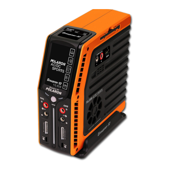
- Page 1 No. S2004 2 Channels AC/DC Charger OPERATING INSTRUCTION Please read this manual thoroughly. Keep this manual in a convenient place for quick and easy reference.
-
Page 2: Table Of Contents
BRUSHED MOTOR TEST CONFIGURATION 32-33 WARMER CONFIGURATION USER SETUP PAGE 34-35 FACTORY MODE CONFIGURATION AND SCREEN CALIBRATION 35-38 DATA INITIALIZATION (FACTORY MODE) 37-38 TOUCH CALIBRATION (TOUCH SCREEN COMPENSATION) 39-41 ERROR MESSAGE USE OF PROBLEM AND PRECAUTION FOR POLARON AC/DC SPORTS CHARGER... -
Page 3: Before Use
3245 University Ave, Suite 1520, San Diego, CA 92104, United States of America Phone: +1 855-5-RCisHoTT ( +1 855-572-4746) Fax: +1 855-546-0350 E-mail: service@openhobby.com ©2014 Graupner/SJ USA – OPENHOBBY LLC. The HoTT trademark is used with permission of SJ Inc. 4386066... -
Page 4: Box Contents
◎ BOX CONTENTS 1. Charger 2. 7 Cells Balance board/Cable (EH to XH) (2 pairs) 3. Temperature sensor (2pcs) 4. USB cable 5. Output cable with alligator clip (2 pairs) 6. Charger rack (optional) 7. User manual 8. Warranty card 9. - Page 5 - If possible, place the battery in a safety bag during the charging or discharging process. - Pay attention to the charger during use. Do not leave the charger unattended. - If the charger becomes hot, disconnect the battery and remove the input power immediately. Allow the charger and the battery to completely cool down before reconnecting.
- Page 6 - Do not charge inside your car. It may cause a fire. - Do not charge with the cigarette lighter socket in the car. Graupner/SJ is not liable for the damage causing by the dismantled input connector. - This charger in only intended for charging R/C battery. Consult with the battery manufacturer when you use other batteries.
-
Page 7: Specifications
USB 5V output (5.0V 1.0A ) / USB B-Type Sub Function Motor Test, Warmer, E.S.C setting External Mini USB device Firmware upgrade Graupner/SJ Logging Software PC communication Optional ( Basically English) Languages Cooling system 50x50x10mm x 2ea Dynamic Cooling Fan Ext. -
Page 8: Charger Control Identification
◎ CHARGER CONTROL IDENTIFICATION BACK ③ ④ ① ⑤ ② ⑥ ① EXT.MODE Socket ② Mini USB ③ Cooling Fan ④ DC Input (12V) ⑤ AC Input ⑥ Power Switch (100 ~ 240V) - Page 9 FRONT RIGHT ⑦ ⑭ ⑧ ⑮ ⑨ ⑩ ⑪ ⑫ ⑬ ⑧ LED Indicator for Charge / Discharge ⑨ Channel Selection Button (CH1/CH2) ⑦ Black & white 128x64 graphic ⑪ Output of the Charger ⑫ Balance Port LCD W/ Touch screen ⑩...
-
Page 10: Menu Configuration
◎ BATTERY CONNECTION POLARON AC/DC SPORTS chargers have two sets of outputs on the front of the charger. Channel 1 is on the left. Channel 2 is on the right. Each channel has two 4mm banana sockets with a 7 cell balance port and a temperature sensor input port. -
Page 11: Input Power Setup
capacity than other cells, over time, the pack can become unbalanced. For an unbalanced pack, some of the cells can exceed the maximum voltage during the charging process, with other cells falling below the minimum voltage during discharge processes. Both circumstances can cause damage to the cells. For an overcharged Lithium cell, damage can occur, with extreme conditions resulting in a fire. -
Page 12: Display
Display Memory number & Battery name Battery type Section 1 Battery Cell quantity and Voltage Battery capacity Section 2 1) Tap the memory number box in section 1 to activate. Tap the INC/DEC buttons to set the memory number. The numbers 0-19 are available and changeable. Press and hold the memory number box to access the battery name page. -
Page 13: Charge Page
◎ CHARGE PAGE To access the charge mode, tap the CHARGE icon on the main page. The parameters in this mode are dependant on the selected battery type that was set on the profile page. Tap the CHARGE icon on the main page to initiate the charging process. -
Page 14: Nicd/ Nimh Battery Charge Setup
: Cut-off temperature. Detected using an optional temperature sensor, a safety cut-off - Cut-Temp temperature can be set to automatically terminate charging or discharging processes. This termination can occur for battery temperatures exceeding a preset value. : The maximum capacity setting is used to terminate a charge. The maximum capacity is - Max Capacity used to prevent the battery capacity from exceeding a preset percentage. -
Page 15: Lipo, Lilon, Life, Nicd, Nimh, Pb Battery Charge Processes
The programmed data are stored in the memory and used to charge the batteries. Tapping the Enter button initiates the charging process. The balance connector verification, the charge mode verification, the number of cells to be charged, and the delay time setup should be finished prior to the charging process. - Page 16 [ NORMAL ] NiCd/NiMH : The charger will charge the pack with a preset charge current, stopping the charging process every minute to calculate the voltage and detect the Delta peak. This process allows for im- proved peak detection, determining the amount of battery wear and instabilties in the charge cable. [ LINEAR ] NiCd/NiMH : The charger will charge the pack with the preset charge current, detecting the Delta peak every second without stopping the charging process.
- Page 17 Charge modes for the POLARON AC/DC CHARGER LiPo, LiIon, LiFe CC-CV : Normal charge. FAST : Fast charge. STORE : Normal store charge. CV-LINK : The packs that have the same number of cells and capacity can be charged simultaneously (If the cells are different, errors can occur.) NiCd, NiMH AUTO : The charge will automatically adjust the charging conditions.
- Page 18 ※ On operation, whenever tapping the current value part, the cycle data screen will be shown. And the charge status could be checked. And tap it gain and the screen will be escaped.
-
Page 19: Discharge Page
◎ DISCHARGE PAGE At the main mode, click the DCHG icon and you can move to the DISCHARGE mode. USER NAME On the main page, tap the DCHG icon to start the discharge process. Tapping the part in the red circle (image on the left) will activate the parameters (blue), allowing the values to be programmed into the data spots. -
Page 20: Lipo, Lilon, Life, Nicd, Nimh Battery Discharge Processes
The programmed data are stored to memory to be used in the battery discharge process. Tapping the Enter button causes the charger to initiate the preliminary steps, including a check of the balance connector, discharge mode, number of cells, and the delay time setup. - Page 21 The charger will stop the discharging process every minute to calculate the average resistance. [ LINEAR ] The charger will discharge the pack, stopping once after 3 minutes to calculate the internal resistance. Discharge mode for the POLARON AC/DC SPORTS CHARGER LiPo, LiIon, LiFe NORMAL : Normal discharge.
-
Page 22: Cycle Page
※ On operation, whenever tapping the current value part, the discharge data screen will be shown. And the discharge status could be checked. And tap it gain and the screen will be escaped. ◎ CYCLE PAGE At the main mode, click the CYCLE icon and you can move to the Cycle mode. And you could configure the data pressing the DEC and INC button. -
Page 23: Cycle Mode Configuration For Lipo, Lilon, Life, Nicd, Nimh, Pb Battery
Cycle Mode Configuration for LiPo, Lilon, LiFe, NiCd, NiMH, Pb Battery Tap the screen and activate the item as white color. And you can input the data. The Charge/Discharge Current cannot be configured at this screen. The configured values at the Charge/Discharge Mode shall be progressed. -
Page 24: Cycle Operation Mode For Each Battery
It will be available from 1 to 150 min. This is a reserved timer for starting the Charge/Discharge cycle. Cycle Operation Mode for each battery. Cycle Mode Charge/Discharge of POLARON AC/DC SPORTS LiPo, LiIon, LiFe, Pb CC-CV: Normal Charge NORMAL: Normal Discharge option... - Page 25 (4) Current Change during Cycling After cycle start, to change the charge/discharge current, tap the related part and you can change the desired cur- rent at the white colored screen. After configuration, tap it again and you can escape from the setting. This config- uration shall be applied for the current charge/discharge operation NOT for charge data configuration.
-
Page 26: Balance Page
◎ BALANCE PAGE At the main mode, click the BALANCE icon and you can move to the BALANCE mode. After pressing the “LEFT, RIGHT, DEC, INC” buttons, the below 4 screens will be shown. Tap the balancing mark long and it will be changed to the stand-by mode for start. This mode could be applied to LiPo, Liion, LiFe batteries installed the balancer connectors. -
Page 27: Data View Page
▲ BALANCE MODE 3 ▲ BALANCE MODE 4 It could be checked the voltage and internal resistance of each cell during balancing. 1) BALANCE MODE 1: The current voltage of each cell 2) BALANCE MODE 2: The internal resistance value of each cell 3) BALANCE MODE 3: The current voltage during the balancing 4) BALANCE MODE 4: The internal resistance value during the balancing ◎... -
Page 28: Misc Page (Addition Function)
Charge time Cycle number Charge capacity Discharge time Peak voltage Discharge capacity Internal resistance Average voltage of charging battery Internal resistance of Discharging battery CYCLE DATA GRAPH DATA ▲ ▲ 1) CYCLE DATA : After changing the cycle number, you can check the data. - Charging time, Discharging time, charge/discharge finishing time - Peak voltage: max voltage during charging - Average voltage: average voltage during charging... -
Page 29: Brushed Motor Test Configuration
Initial screen of MISC mode Tap the 2 icons and the mode will be moved to the mode. At the each mode, tap the ESC button and it will be returned to the initial screen of MISC mode. - Brushed Motor Test Function - Battery and Tire Warmer Function Brushed Motor Test Configuration Connect the Motor with banana socket for charging at the front side. - Page 30 1) BREAK-IN - The motor could be rotated with configured voltage during the set time. Operation time: min and second Operating voltage configuration Press the START button and it shows operating time, voltage and current consumption. 2) PROGRAM - At the 4 step, you can configure for the voltage, operating time, resting time and cycle counts.
-
Page 31: Warmer Configuration
3) MOTOR TEST - Activate the motor test and it shows average current (Aa) and max curren (Ap) with 6 steps. The voltage configuration could be for 4.8V and 7.2V. Test voltage configuration : 4.8V / 7.2V 5 sec on and 3 sec off: 1~6 steps Average current and max current of the motor 4.8V : 4 steps 7.2V : 6 steps... - Page 32 Progress time during operation Temperature configuration After alarm configuration with the time, it could be stopped by ESC button. Output voltage configuration: It will be controlled automatically with temp sensor in- stallation. Without the sensor, it shows the configured voltage (5~15V). Without temp sensor, the temperature could not be controlled automatically.
- Page 33 ◎ User Configuration Page At the main screen, tap the USER SET icon and it will be moved to user configuration mode. There are 5 screens. Using the left and right button, the screen could be moved and the data could be configured At the main screen, pick the icon to move to the User Configuration.
- Page 34 DC IN : Automatic activation from rear Wattage of input power supply side connection (DC11~15V) AC-IN : Automatic activation from rear Input for the voltage and current of side by AC cable connection. power supply Wattage sharing (%) of charger 1 & Error configuration for low voltage 2 CH Input...
-
Page 35: Factory Mode Configuration And Screen Calibration
◎ Factory mode configuration and Screen calibration Touch area for touch Screen calibration Channel change and Factory mode button Pressing the Factory mode button or touching the touch area, please power on. -
Page 36: Data Initialization (Factory Mode)
1. Data Initialization (Factory mode) Pressing the Factory mode button, please power on. And it will be shown as below. It is a stand-by screen for data It is under initialization. After com- initialization. Tap the right low but- pletion, the screen will be automati- ton, and start initializing. - Page 37 Touch left low and right up step by step. And touch left low of right low button and right up of right up button step by step. And then, the screen shall be aligned. After completion, it will be automatically restarted to the charge mode.
-
Page 38: Error Message
◎ Error Message POLARON AC/DC SPORTS charger shows error message to the user. When the error happens, all operation shall be stopped and the charger will show error message with error sound. It will be cleared if you tap the error screen. And the screen will be returned to the previous screen. - Page 39 ◆ In case of improper battery voltage configuration or over-discharge, please make sure the voltage config- uration. ◆ In case the temperature is below 0°C during oper- ation and below -10°C at normal condition, the error message shows. Please make sure the temp sensor connection.
- Page 40 ◆ The causes are over-charging, the point of bal- ancer connector and the cable condition. Please make sure the configuration and condition of the charger, cable and connector. ◆ In this case, please request A/S to our service centre. ◆ Please the temp sensor connection. ◆...
-
Page 41: Use Of Problem And Precaution For Polaron Ac/Dc Sports Charger
◎ USE OF PROBLEM AND PRECAUTION FOR POLARON AC/DC SPORTS CHARGER - The charger has been turned on, but the Screen is off. . Check that the external power source is an appropriate source. . This charger should be operated only with the types of power sources that are indicated on the specifications. - Page 42 ◎ NiCd, NiMH BATTERY SAFETY - With charging new NiCd/ NiMH batteries for the first time, the process may terminate within minutes. This stoppage does not indicate a problem. This stoppage results from an unstabilized battery. To stabilize the batteries, charge the batteries either after increasing the delta peak value or after performing a discharging process followed by a cooling down period.
- Page 43 - When used correctly, Lithium ion/Polymer/Fe battery packs are as safe as any other type of rechargeable battery pack. However, these batteries do require different charge regimes than the more established Nickel Cadmium and Nickel Metal Hydride technologies and have the potential for catching fire, if severely mistreated.
- Page 44 ◎ The Guide for the related Countries’ Certifications Conformite Europeenne EMC NO. BCT13FR - 1067E (CE 인증 진행 중) LVD NO. BCT13FR - 1067S Product(s): POLARON AC/DC Charger Item Number(s): S2004 The object of declaration described above is in conformity with the requirements of the specifications listed below, and accordance with the following applicable directives: 2004/108/EC Electromagnetic Compatibility 2006/95/EC Low Voltage Directive...
- Page 45 ◎ ENVIRONMENTAL PROTECTION NOTES This product must not be disposed of with other waste. Instead, it is the user’s responsibility to their waste equipment by handing it over to a designated collection point for the recycling of waste electrical and electronic equipment.
Need help?
Do you have a question about the POLARON AC/DC SPORTS and is the answer not in the manual?
Questions and answers