
Related Manuals for GRAUPNER Polaron EX


Summary of Contents for GRAUPNER Polaron EX
- Page 1 No. S2011 2 Channels DC Charger OPERATING INSTRUCTION Pease read this manual thoroughly. Keep this manual in a convenient place for quick and easy reference.
-
Page 2: Table Of Contents
SPECIFICATIONS CHARGER CONTROL IDENTIFICATION 9-10 Thank you for purchasing the POLARON EX 2CH DC Charger. Designed for both novices and pro- MENU CONFIGURATION fessionals, this system is extremely versatile. To make the best use of your system, please read this ACTION BUTTONS manual carefully. -
Page 3: Box Contents
- If possible, place the battery in a safety bag during the charging or discharging process. ◎ BOX CONTENTS - Pay attention to the charger during use. Do not leave the charger unattended. - If the charger becomes hot, disconnect the battery and remove the input power immediately. 1. -
Page 4: Specifications
USB 5V output (5.0V 2.5A ) / USB B-Type Servo Test, Motor Test, Warmer, ESC setting Sub Function Firmware upgrade External Mini USB device PC communication Graupner/SJ Logging Software Languages Optional (Primarily English) 50 x 50 x 10mm x 2ea Dynamic Cooling Fan Cooling system Ext. Module socket... -
Page 5: Charger Control Identification
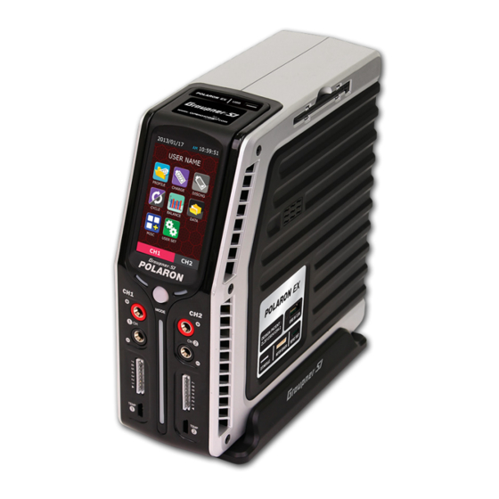
◎ CHARGER CONTROL IDENTIFICATION BACK FRONT RIGHT ④ ⑤ ⑥ ② ⑦ ⑧ ⑪ ① ⑨ ③ ⑩ ⑫ ⑬ ⑭ ⑤ LED Indicator for charge / discharge ① Mini USB ② DC Input ③ Dynamic Cooling Fan ④ 3.0”TFT LCD with Touch Screen ⑥... -
Page 6: Menu Configuration
◎ BATTERY CONNECTION page. This data can be programmed during the USER SET POLARON EX 2CH DC chargers have two sets of outputs on the front of the charger. Channel 1 is on the process. left. Channel 2 is on the right. Each channel has two 4mm banana sockets with a 7 cell balance port and a temperature sensor input port. -
Page 7: Display
Display ◎ CHARGE PAGE PROFILE 00:00:00 Number of cells in series BATTERY NAME To access the charge mode, tap the CHARGE icon on the main page. The parameters in this mode TYPE LiPo Memory number & Battery name are dependant on the selected battery type that was set on the profile page. Section 1 Voltage 25.2... -
Page 8: Nicd/ Nimh Battery Charge Setup
- Cut-Temp : Cut-off temperature. Detected using an optional temperature sensor, a safety cut-off The programmed data are stored in the memory and used to charge the batteries. Tapping the Enter temperature can be set to automatically terminate charging or discharging processes. This button initiates the charging process. - Page 9 [ NORMAL ] Charge modes for the POLARON EX CHARGER NiCd/NiMH : The charger will charge the pack with a preset charge current, stopping the charging LiPo, LiIon, LiFe CC-CV : Normal charge. process every minute to calculate the voltage and detect the Delta peak. This process allows for im- FAST : Fast charge.
-
Page 10: Discharge Page
This page (left) shows the charging process with the parameters ◎ DISCHARGE PAGE and graph. Both the voltage and current will increase to the preset parameters. The preset current may be limited by the charge/dis- Tapping the DISCHARGE icon on the main page will access the discharge mode. The pro- charge capacity and the input voltage setup. -
Page 11: Lipo, Lilon, Life, Nicd, Nimh, Batteries Discharge Processes
The discharge process starts immediately after these preliminary steps. With proper programming, the charger will display a 5-second countdown. The discharging sequence is shown below. Discharge mode for the POLARON EX CHARGER LiPo, Lilon, LiFe, NiCd, NiMH battery discharge processes LiPo, LiIon, LiFe NORMAL : Normal discharge. -
Page 12: Cycle Page
This page (left) shows a display of the discharging process USER NAME with the parameters and graph. Both the voltage and cur- rent will increase to the preset parameters. The preset cur- rent value may be limited by the charge/discharge capacity Tap the CYCLE icon on the main and the input voltage setup. -
Page 13: Cycle Operation Mode Per Battery Type
The preset current may be limited by the charge/discharge capacity and ithe nput voltage setup. The max charging process operates at 400W with Cycle charge discharge mode of the POLARON EX Charger a max discharging process at 60W. LiPo, LiIon, LiFe, Pb... -
Page 14: Balance Page
Center voltage Range voltage Pressing the STOP button will cause the pop-up window to appear, asking for a confimation that you want to stop the operation. Tapping either the STOP or ESC button will cause the charger to either stop or continue the cycle, respectively. -
Page 15: User Setup Page
▲ GRAPH DATA ▲ CONFIG MODE 1 Input ONLY for Graupner/SJ Input of the User’s SMSP from the rear side Side-Docking SMPS (Model No. S2012) 1) NORMAL DATA : Real time display of the input/output voltage, temperature, resistance of bat- tery. -
Page 16: Misc Page (Addition Function)
1) Servo test division (Screen top) ◎ MISC PAGE (Addition function) - Connect the Servo to the connecter on the right side of the charger (see picture, below). Tap the MISC icon on the main page to access the MISC mode and to program the Servo, Brushless/Brushed power motor, and Warmer functions. -
Page 17: Brushed Motor Setup
The optional accessory Brushed motor setup Connect the motor to a 4mm banana charge socket. Tap the MOTOR icon to access the motor setup mode. This page has 3 menus. Wire splitter for testing the motor sensor (S8002) Connection configuration for the ESC, Motor, Battery, and Wire splitter 1) Break-In - The motor is operated and limited by the preset voltage for the preset time. -
Page 18: Warmer Setup
Setting the number of cycles (1-10 cycles) Setting the operating voltage, the operating time, and the delay time, for each of the 4 steps. The operating cycle number. 1) Battery Warmer - At low temperatures, lithium type batteries tend not to perform well. This function is used 3) Motor test to warm up the batteries to ensure proper function for batteries stored outdoors. - Page 19 Connection configuration for the ESC setup (Charger, ESC, Motor, Battery, Receiver included) Temperature setup Alarm setup Alarm rings at the preset time. The charger continues op- erating. Tap the STOP button to stop the alarm. Output voltage setup With an installed temperature sensor, this feature is controlled au- tomatically.
-
Page 20: Factory Setup And Screen Calibration
Data Initialization ◎ FACTORY SETUP AND SCREEN CALIBRATION *** Factory Data *** Tap No1 to access the factory data mode. Initializing Data... The blinking characters alternate between red and blue, indicating that the program is operational. After the Data Initialization has completed, the return to the Start up page will proceed automatically. -
Page 21: Resource Upgrade
RESOURCE UPGRADE <Image & Sound> Press the button. POLARON EX DC chargers have a number of error and ‘Download Start ’ warning messages that are designed to advise the user of any problems. Tapping the error message can clear the <... - Page 22 Low Output-Volt BLC Volt Low Output voltage is lower Balancer cell voltage is ◆ A Low Output-Volt error message indicates that than the selected cells too low ! ◆ A BLC Volt Low error message indicates that either the voltage setup is below the requirements for or voltages.
-
Page 23: Common Problems And Precautions For The Polaron Ex Dc Charger
◎ NiCd, NiMH BATTERY SAFETY ◎ COMMON PROBLEMS AND PRECAUTIONS FOR THE POLARON EX DC CHARGER - The charger has been turned on, but the LCD Screen is off. - With charging new NiCd/ NiMH batteries for the first time, the process may terminate . -
Page 24: The Guide For The Related Countries'certifications
Allowing the voltage to fall below 3 volts per cell will invalidate all warranty claims. Model: POLARON EX DC Battery Charger - Never charge Lithium Polymer battery packs to values exceeding 4.2V per cell, Lithium Ion batteries Item Number(s): S2011 exceeding 4.1V volts per cell or LiFe batteries exceeding 3.7V per cell.
Need help?
Do you have a question about the Polaron EX and is the answer not in the manual?
Questions and answers