Table of Contents
Advertisement
Quick Links
Advertisement
Table of Contents

Related Manuals for GRAUPNER S2003


Summary of Contents for GRAUPNER S2003
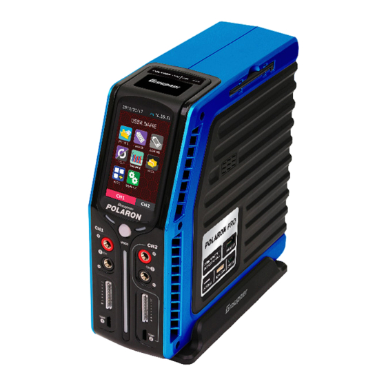
- Page 1 2 Channels DC Charger OPERATING INSTRUCTION Please read this manual thoroughly. Keep this manual in a convenient place for quick and easy reference. ©2014 Graupner/SJ USA – OPENHOBBY LLC. The HoTT trademark is used with permission of Graupner Co., Ltd. 4386066...
-
Page 2: Table Of Contents
FACTORY SETUP AND SCREEN CALIBRATION 39-41 Phone: +1 855-5-RCisHoTT ( +1 855-572-4746) Fax: +1 855-546-0350 DATA INITIALIZATION E-mail: service@openhobby.com TOUCH CALIBRATION RESOURCE UPGRADE ©2014 Graupner/SJ USA – OPENHOBBY LLC. The HoTT trademark is used with permission of SJ Inc. 4386066 BLC PORT TEST... -
Page 3: Box Contents
- If possible, place the battery in a safety bag during the charging or discharging process. ◎ BOX CONTENTS - Pay attention to the charger during use. Do not leave the charger unattended. 1. Charger - If the charger becomes hot, disconnect the battery and remove the input power immediately. 2. -
Page 4: Specifications
- Connect the battery pack to a balance board. Without this connection, either the batteries ◎ SPECIFICATIONS or the charger may be damaged. MODE SPECIFICATION (CH1) (CH2) - Do not charge a battery with a voltage below 2.8V per cell. If this type of battery is forced 11-28V PROternal DC Power Supply Power source (Docking system) -
Page 5: Charger Control Identification
◎ CHARGER CONTROL IDENTIFICATION BACK FRONT RIGHT ④ ⑤ ⑥ ② ⑦ ⑧ ⑪ ① ⑨ ③ ⑩ ⑫ ⑬ ⑭ ① Mini USB ② DC Input ③ Cooling Fan ④ 3.0”TFT LCD with Touch Screen ⑤ LED Indicator for charge / discharge ⑥... -
Page 6: Menu Configuration
Both circumstances can cause damage to the cells. For Graupner POLARON Series chargers are equipped with a highly sensitive touch screen. Touch an overcharged Lithium cell, damage can occur, with extreme conditions resulting in a fire. -
Page 7: Display
Display ◎ CHARGE PAGE To access the charge mode, tap the CHARGE icon on the main page. The parameters in this mode Memory number & Battery name are dependant on the selected battery type that was set on the profile page. Section 1 Battery type Battery voltage... -
Page 8: Nicd/ Nimh Battery Charge Setup
- Cut-Temp : Cut-off temperature. Detected using an optional temperature sensor, a safety cut-off The programmed data are stored in the memory and used to charge the batteries. Tapping the Enter temperature can be set to automatically terminate charging or discharging processes. This button initiates the charging process. - Page 9 [ NORMAL ] Charge modes for the POLARON PRO CHARGER NiCd/NiMH : The charger will charge the pack with a preset charge current, stopping the charging LiPo, LiIon, LiFe CC-CV : Normal charge. process every minute to calculate the voltage and detect the Delta peak. This process allows for im- FAST : Fast charge.
-
Page 10: Discharge Page
This page (left) shows the charging process with the parameters ◎ DISCHARGE PAGE and graph. Both the voltage and current will increase to the preset parameters. The preset current may be limited by the charge/dis- Tapping the DISCHARGE icon on the main page will access the discharge mode. The pro- charge capacity and the input voltage setup. -
Page 11: Lipo, Lilon, Life, Nicd, Nimh, Batteries Discharge Processes
The programmed data are stored to memory to be used in the battery discharge process. [ NORMAL ] Tapping the Enter button causes the charger to initiate the preliminary steps, including The charger will stop the discharging process every minute to calculate the average resistance. [ LINEAR ] a check of the balance connector, discharge mode, number of cells, and the delay time The charger will discharge the pack, stopping once after 3 minutes to calculate the internal resistance. -
Page 12: Cycle Page
This page (left) shows a display of the discharging pro- USER NAME cess with the parameters and graph. Both the voltage and current will increase to the preset parameters. The pre- set current value may be limited by the charge/discharge Tap the CYCLE icon on the main capacity and the input voltage setup. -
Page 13: Cycle Operation Mode Per Battery Type
Charge mode selection in cycle mode Discharge mode selection in cycle mode Number of cells checking The charge mode and the start delay time parameters are programmed. After connecting the balance board, the charger can check Tap the box to activate (blue). Tap the DEC/INC button to select the the number of cells. -
Page 14: Balance Page
Center voltage Pressing the STOP button will cause the pop-up window Range voltage to appear, asking for a confimation that you want to stop the operation. Tapping either the STOP or ESC button will cause the charger to either stop or continue the cycle, respectively. -
Page 15: User Setup Page
Finish Sound : 10 types of sounds are available. Cycle number Sound Time : The times available for the charger are Discharge time Charge time ON, OFF, 5sec, 15sec, and 1min. Beep : This parameter can be turned on/off to select Average voltage Peak voltage either an internal or an external button. -
Page 16: Misc Page (Addition Function)
1) Servo test division (Screen top) ◎ MISC PAGE (Addition function) - Connect the Servo to the connecter on the right side of the charger Tap the MISC icon on the main page to access the MISC mode and to program the (see picture, below). -
Page 17: Brushed Motor Setup
The optional accessory Brushed motor setup Connect the motor to a 4mm banana charge socket. Tap the MOTOR icon to access the motor setup mode. This page has 3 menus. Wire splitter for testing the motor sensor (S8002) Connection configuration for the ESC, Motor, Battery, and Wire splitter 1) Break-In - The motor is operated and limited by the preset voltage for the preset time. -
Page 18: Warmer Setup
Setting the number of cycles (1-10 cycles) Setting the operating voltage, the operating time, and the delay time, for each of the 4 steps. The operating cycle number. 1) Battery Warmer - At low temperatures, lithium type batteries tend not to perform well. This function is used 3) Motor test to warm up the batteries to ensure proper function for batteries stored outdoors. - Page 19 Connection configuration for the ESC setup (Charger, ESC, Motor, Battery, Receiver included) Temperature setup Alarm setup Alarm rings at the preset time. The charger continues op- erating. Tap the STOP button to stop the alarm. Output voltage setup With an installed temperature sensor, this feature is controlled au- tomatically.
-
Page 20: Factory Setup And Screen Calibration
Data Initialization ◎ FACTORY SETUP AND SCREEN CALIBRATION *** Factory Data *** Tap No1 to access the factory data mode. Initializing Data... The blinking characters alternate between red and blue, indicating that the program is operational. After the Data Initialization has completed, the return to the Start up page will proceed automatically. -
Page 21: Resource Upgrade
Smart BMS *POLARON* 1. This screen is used to downlowed image and sound files from a PC to the flash memory in the charger. 2. Program updates are found at www.openhobby.com and www.graupner.co.kr BLC Port Test (Checking balance port) No Battery Battery is not connected to the output. - Page 22 Low Output-Volt BLC Volt Low Output voltage is lower Balancer cell voltage is ◆ A Low Output-Volt error message indicates that than the selected cells too low ! ◆ A BLC Volt Low error message indicates that either the voltage setup is below the requirements for or voltages.
-
Page 23: Common Problems And Precautions For The Polaron Pro Dc Charger
◎ NiCd, NiMH BATTERY SAFETY ◎ COMMON PROBLEMS AND PRECAUTIONS FOR THE POLARON PRO DC CHARGER - The charger has been turned on, but the LCD Screen is off. - With charging new NiCd/ NiMH batteries for the first time, the process may terminate . -
Page 24: The Guide For The Related Countries'certifications
- Lithium Ion/Polymer battery packs must NEVER be discharged below 3 volts per cell (Li-Fe 2.0V), as Item Number(s): S2003 this will result in damage to the cells. If the voltage is allowed to drop below 3 volts per cell, the...
Need help?
Do you have a question about the S2003 and is the answer not in the manual?
Questions and answers