Xerox Phaser 3117 Service Manual
Laser printer
Hide thumbs
Also See for Phaser 3117:
- Upgrade instructions (8 pages) ,
- Specifications (2 pages) ,
- User manual (104 pages)
Table of Contents
Advertisement
Quick Links
SERVICE
LASER PRINTER
LASER PRINTER
LASER PRINTER
LASER PRINTER
LASER PRINTER
Phaser 3117
Manual
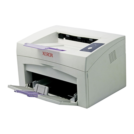
The keynote of Product
- Speed : 17ppm (Ltr) / 16ppm(A4), 600dpi
- Paper Path : MPF Type Cassette
- Emulation : SPL
- Processor : 150MHz Jupiter4e CPU
- Memory : SDRAM,8MB,
- MP Cassette : 150 pages / Face Down
(50 pages)
- Fuser Design : Lamp Type
- I/O : USB1.1
- Machine Life : 50K(pages)
x
Advertisement
Table of Contents

Related Manuals for Xerox Phaser 3117


Summary of Contents for Xerox Phaser 3117
-
Page 1: Laser Printer
LASER PRINTER Phaser 3117 Manual SERVICE LASER PRINTER LASER PRINTER LASER PRINTER LASER PRINTER The keynote of Product - Speed : 17ppm (Ltr) / 16ppm(A4), 600dpi - Paper Path : MPF Type Cassette - Emulation : SPL - Processor : 150MHz Jupiter4e CPU... -
Page 2: Table Of Contents
Contents 1. Precautions 1.1 Safety Warning 1.2 Safety Caution 1.3 ESD Precautions 2. Product Specification 2.1 Product Overview 2.2 Specifications 2.3 Model Comparison Table 3. System Overview 3.1 System Outline 3.2 H/W Structure and Descriptions 3.3 S/W Structure and Descriptions 3-19 3.4 Initial Product Installation 3-24... - Page 3 Continued 5. Disassembly and Reassembly 5.1 General Precautions on Disassembly 5.2 Disassembly and Reassembly 6. Troubleshooting 6.1 Checking Symptoms 6.2 Bad discharge 6.3 Malfunction 6.4 Bad software environment 6-13 6.5 Bad Image 6-17 7. Exploded Views & Parts List 7.1 Exploded Views and Parts List 8.
- Page 4 Continued 11. Reference Information 11.1 Troubleshooting Tools 11-1 11.2 Acronyms and Abbreviations 11-2 11.3 Selecting printer locations 11-4 11.4 Sample Tests Patterns 11-5 12. Circuit Description 12.1 Engine Controller 12-1...
-
Page 5: Precautions
1.1 Safety Warning (1) Request service by qualified service person. Service for this machine must be performed by a Qualified Xerox service person. It is dangerous if unqualified service personnel or users try to fix the machine. (2) Do not rebuild. -
Page 6: Safety Caution
Precautions 1.2 Safety Caution 1.2.1 Noxious Material Precaution The toner in a printer cartridge contains a chemical material, which may harm human body if it is swallowed. Please keep children out of reach of the toner cartridge. 1.2.2 Electric Shock or fire Precaution It is possible to get electric shock or burn by fire if you don't fallow the instructions of the manual. -
Page 7: Handling Precautions
Precautions 1.2.3 Handling Precautions If you ignore this information, you could harm machine and could be damaged. (1) Do not install it on different levels, or slanted floor. Please confirm whether it is balanced or not after installation. If it is unbalanced, an accident can be hap- pened due to the machine falling over. -
Page 8: Esd Precautions
Precautions 1.3 ESD Precautions Certain semiconductor devices can be easily damaged by static electricity. Such components are commonly called “Electrostatically Sensitive (ES) Devices”, or ESDs. Examples of typical ESDs are: integrated circuits, some field effect transistors, and semiconductor “chip” components. The techniques outlined below should be followed to help reduce the incidence of component damage caused by static electricity. -
Page 9: Product Specification
Product Specifications 2. Product Specifications 2.1 Product Overview Item Descriptions Remark Basic Model Phaser 3117 Series Model Phaser Family Market of Sailes Persnal user Laser printer.(Low Price for small work Group.) Specification 16ppm (A4) Ltr. 17ppm, Jupiter 4e 150MHz, 2Mbytes SDRAM Toner 1K(initial), 3K(sailes) USB 1.1 Model(Compatible with USB 2.0),... - Page 10 Product Specifications Item Descriptions Periodic Replacing Parts Pick Up Roller : 50,000 Pages Same with Machine Life Transfer Roller : 50,000 Pages Fuser Assembly : 50,000 Pages Toner Sensor Toner Type Non-Magnetic Contact System Toner Initial 1,000 sheets@ISO 5% coverage Toner sale 3,000 sheets@ISO 5% coverage Cassette...
-
Page 11: Electrical Specification
Product Specifications 2.2.3 Electrical Specification Item Descriptions Remark Input Voltage Nominal input voltage 220~240 VAC Input voltage range 198~255 VAC Nominal frequency 50/60 MHz Frequency tolerance +3Hz Power Consumption Printing : 300W Avg(Max. 500W) Idling : 100W Avg or less Power Save : 10W Avg or less 2.2.4 Environmental Range Item... -
Page 12: Paper Handling Specifications
Product Specifications 2.2.6 Paper Handling Specifications Please refer to Paper Secifications on user Guide. 2.2.6.1 Input Paper Size Paper paper size Cassette 210 X 297 mm Letter 216 X 279(8.5 X 11") US Folio(Legal13") 216 X 330(8.5 X 13") Legal(Legal14") 216 X 356(8.5 X14") Executive 184 X 267((7.25 X10.5") - Page 13 Product Specifications 2.3 Model Specification Table Model Name Phaser 3117 General Company Xerox Printing Process Print Method: Electrophotographic Laser Print Speed Up to 16ppm in A4, Up to 17ppm in letter FPOT 10sec Resolusion 600*600 Duty Cycle, Monthly up to 4166 prints per month...
-
Page 14: System Overview
System Overview 3. System Overview 3.1 System Outline Paper Path Layout ¦ò BIN PATH ¦å SMPS ¦æ Fuser ¦ç Toner Cartridge ¦è LSU ¦é Exit Roller ¦ê OPC ¦ë Pick-Up Roller ¦ì KNOCK-UP PLATE ¦í KNOCK-UP PLATE DOWN ¦î ASS’Y HOLDER PAD ¦ï... - Page 15 System Overview Unit Layout Panel HVPS Motor SMPS Main PBA Service Manual...
- Page 16 System Overview 3.1.1 Feeding There are the C-path type, which loads papers, and the manual feeder, which supplies paper one by one.The cassette has the function pad which separates paper one by one, and it has the sensor function to check the existence of the loading paper.
- Page 17 System Overview 1) Heat Lamp . Heat Lamp Terminal Shape : Terminal Single Type . Voltage 120 V : 115 + /- 5 % 220 V : 230 + /- 5 % . Capacity : 600 Watt + /- 30 W .
- Page 18 System Overview 3.1.5 LSU (Laser Scanner Unit) The LSU unit is controlled by video controller. It scans the video data received from video controller with laser beam by using the rotation principle of the polygon mirror to create the latent image on the OPC drum. It is the core part of LBP.
-
Page 19: Toner Cartridge
System Overview 3.1.6 Toner Cartridge By using the electronic photo process, it creates a visual image. In the toner cartridge, the OPC unit and the developer unit are in a body. The OPC unit has OPC drum and charging roller, and the developer unit has toner, toner cartridge, supply roller, developing roller, and blade (Doctor blade) - Developing Method: Non magnetic 1 element contacting method - Toner: Non magnetic 1 element shatter type toner... -
Page 20: H/W Structure And Descriptions
Engine B’D 3.2.1.1. Main Control Phaser 3117 of Main Control are composed of CPU and Print and operate follows function by CPU - Bus Control, I/o - Handling, each Driver and PC Interface Main Control operate its full function on the Main B'd and CPU control Controller ASIC and build-in Memory. - Page 21 System Overview - Main Function Block: Completely Integrated System for Embedded Applications, 32 Bit Risc Architecture, Efficient and Powerful ARM9 CPU LSU Interface Module for Interfacing PVC with LSU 2 Channel General Purpose DMA Controller for High Speed I/O Dual Memory Bus Architecture - Operation Frequency : 150MHz - Operation Voltage : 3.3V - POWER ON RESET TIME : 6.6ms below...
- Page 22 System Overview 3.2.2 Main Board Main Board are composed of Engine and Controller on the one-Board. Main Board control to send Current Imagedml Video Data to LSU to print and have motor Driving and Circuit for the current driving and also include Paper Exit Sensor, Cover Open s/w, panel s/w. (IC-VOLTAGE COMP) (IC-CLOCK GENERATOR) 12.0MHz...
- Page 23 System Overview U6(Jupiter 4E) - It is a main CPU and an Asic of Jupiter4E which has a CPU core CLK with over 150MHz and a System bus 45MHz. - It use 3.3V for operation voltage and I/O, It uses 80MHz for system bus CLK, SDRAM - Main memory.
- Page 24 System Overview 3.2.3 Asic(SPGPm) Specification 3.2.3.1 Introduction Jupiter4E is One-Chip micro-Controller for Low cust Laser beam Printer. 1. One Chip Laser Beam Printer Controller - GDI only - AMBA AHB used for high speed bus transactions between masters and slaves - AMBA APB used for low speed bus transactions between ARM core and peripherals - 3 PLLs ( 2 Dithered PLL and 1 General PLL) first for CPU(150MHz), AHB(75MHz), APB(75MHz),...
- Page 25 System Overview 8. Interrupt Controller (INTC) - FIQ or IRQ mode operation selectable - Programmable Interrupt Enable/Disable 9. USB interface - Version 1.1 - Four 128x8 FIFOs for Data transmission. - Interrupt based input / output interface, no DMA based interface support - USB wrapper for AHB interface - AHB Bus interface 10.
- Page 26 System Overview 3.2.3.2 Jupiter4E Internal Block Diagram AHBC ( ARB, DEC, MUX) ARM CORE FL ASH CO RE ( ARM940T PROGRAM ( mfl130_128Kx32 I / C 4 KB ENEXHV D/ C 4 KB ) EXHV nTRST DC2-0 nSRAS nSCAS SDRAMC nSCS DQM1-0 ( EXT :...
- Page 27 If it could not detect the feed sensor within 1 second after feeding a paper, a paper jam0 (CPU#_) occurs. Phaser 3117 differs from other general printers because it doesn’t have a paper empty sensor. It recognizes the paper existing status by using a firmware. If a paper is not fed, it recognizes the state as no paper (Red and Yellow lights turn on among other LEDs).
- Page 28 System Overview 3.2.5 SMPS board (Switching Module Power Supply) The SMPS supplies DC Power to the System. It takes 110V/220V and outputs the +5V, +24V to supply the power to the main board and other board. It is consisted of the AMPS part, which supplies the DC power for driving the system, and the AC heater control part, which supplies the power to fuser.
- Page 29 System Overview 1) SMPS Specification - AC Input Input Rated Voltage : AC 220V ~ 240V AC 120V / AC 220V(EXP version) Input Voltage fluctuating range : AC 90V ~ 135V / AC 180V ~ 270V(EXP version) Rated Frequency : 50/60 Hz Frequency Fluctuating range : 47 ~ 63 Hz Input Current : Under 4.0Arms / 2.5Arms (But, the status when lamp is off or rated voltage is inputted/outputted )
- Page 30 System Overview - Environment Condition . Operating temperature range : 0 . Maintaining temperature range : -20 . Preserving Humidity Condition : 10% ~ 90% RH . Operating atmospheric pressure range : 1atm - EMI Requirement : CISPR ,FCC, CE, MIC, - Safty Requrement : IEC950 UL1950, CSA950, C-UL,Semko, EK,CB, CCC(CCIB),GOST, EPA, Power Save 3.2.6 HVPS board (High Voltage Power Supply)
- Page 31 System Overview - Output Voltage Falling Time : 50 ms Max - Output Loading range : 10Mߟ ~ 1000 - Output Control Signal (BIAS-PWM) : the CPU output is HV output when PWM is low. 4) Supply - Output Voltage : -550 V 8.6%(ZENER using, DEV ) - Input contrast of the output stability degree : under - Loading contrast :...
-
Page 32: Fuser Ac Power Control
System Overview 3.2.7 FUSER AC POWER CONTROL Fuser(HEAT LAMP) gets heat from AC power. The AV power controls the switch with the Triac, a semiconductor switch. The 'ON/OFF control' is operated when the gate of the Triac is turned on/off by Phototriac (insulting part). In other words, the AC control part is passive circuit, so it turns the heater on/off with taking signal from engine control part. -
Page 33: S/W Structure And Descriptions
Phaser 3117. 3.3.1 Introduction This Engine Control Firmware is a program that controls LBP Engine of the Phaser 3117. This firmware is executed every 10msec as an interrupt routine of the main system. At stand-by state, this firmware monitors the enable print command from the main system. If the enable print command is detected, this firmware controls the Engine Mechanism according to the printing process and paper feeding state. - Page 34 System Overview - Architecture of Engine Control F/W Power On Main F/W of the printer controller Initial Engine F/W Device Units Fixing Unit Interface Control Module HVPS Engine Main Control Module Fan Unit Motors Solenold & Sensing & Unit Control Module Clutch Hardware Devices &...
- Page 35 System Overview 3.3.3 F/W Architecture of Engine Control Firmware - The Engine Control Module is executed every 10msec as interrupt job of main system. There are three control modules, i.e., Engine Main Control Module, Engine Interface Module and Sensing & Unit Control Module.
- Page 36 System Overview - F/W Architecture START Global Timer Increment Get A DC Val ue (Tempe rature, .. ) Control the fi xing unit & Check error condition for the fixing un it Control the fan unit Get status value of each sensor &...
- Page 37 System Overview 3.3.6 LED Behaviors Ready LED Error LED Toner Save LED Status Ready to receive the data. SLOW BLINK Receiving the data from the host. In case that toner save mode is ON. FAST BLINK Printing the page. In case that toner save mode is ON. Recovery mode Out of paper BLINK...
-
Page 38: Initial Product Installation
System Overview 3.4 Initial Product Installation 3.4.1 Accessory List Remove the printer and all accessories from the packing carton. Make sure that the printer has been packed with the following items: 3.4.2 Installing the Toner Cartridge 1. Grasp the front cover and pull it toward you to open. Service Manual 3-25... - Page 39 System Overview 2. Remove the toner cartridge from its bag and remove the paper covering the cartridge. 3. Gently shake the cartridge from side to side to distribute the toner evenly inside the cartridge. 4. Locate the cartridge slots inside the printer, one on each side. Service Manual 3-26...
- Page 40 System Overview 5. Unfold the toner cartridge handle and grasp it. Insert the cartridge in the printer until it snaps into place. 6. Close the front cover. Make sure that the cover is securely closed. If the cover is not firmly closed, printing errors may occur when you print.
-
Page 41: Loading Paper
System Overview 3.4.3 Loading Paper You can load approximately 150 sheets of paper in the tray. 1. Grasp the paper input tray and pull it toward you to open. Pinch the rear guide and pull it out to extend the tray. 2. -
Page 42: Connecting A Printer Cable
System Overview 4. Pay attention not to overload paper. Paper overloading may cause paper jams. 5. If necessary, pinch the rear guide to adjust for the paper length and pinch the side guide and slide it to the left flush against the paper. 3.4.4 Connecting a Printer Cable To print from your computer, you need to connect your printer to your computer with a Universal Serial Bus (USB) cable. -
Page 43: Turning The Printer On
System Overview 3.4.5 Turning the Printer on 1. To print from your computer, you need to connect your printer to your computer with a Universal Serial Bus (USB) cable. 2. Plug the other end into a properly grounded AC outlet and turn on the printer using the power switch. 3.4.6 Printing a Demo Page Print a demo page to make sure that the printer is operating correctly. -
Page 44: Installing Printer Software
System Overview 3.4.7 Installing Printer Software The supplied CD-ROM contains Windows printing software, Linux printing software, on-line User’s Guide and Acrobat Reader to view the User’s Guide. 1. If you are printing from Windows - You can install the following printer software using the CD-ROM. •... -
Page 45: Alignment And Adjustments
Alignment and Adjustments 4. Alignment and Adjustments 4.1 Sample Pattern This product has the several sample patterns for maintenance. With the sample patterns, check the existence of the abnormality. The patterns help to regularly maintain the product. 4.1.1 Printing a Demo Page Print a demo page or a configuration sheet to make sure that the printer is operating correctly. -
Page 46: Control Panel
Alignment and Adjustments 4.2 Control Panel 4.2.1 OP Panel 4.2.2 On Line/Error and Toner Save LEDs Description If the On Line/Error lights green, the printer is ready to print. If the On Line/Error lights red, the printer is experiencing an error, such as jammed paper, no paper, the open cover or the empty toner cartridge. -
Page 47: Cancel Button
Alignment and Adjustments 4.2.3 Cancel button Description Printing demo page In Ready mode, press and hold this button for about 2 seconds until all LEDs blink slowly, and release. Manual feeding Press this button each time you load a sheet of paper in the tray, when you select Manual Feed for Source from your software application. -
Page 48: Consumables And Replacement Parts
Alignment and Adjustments 4.3 Consumables and Replacement Parts The cycle period outlined below is a general guideline for maintenance. The example list is for an average usage of 50 transmitted and received documents per day. Environmental conditions and actual use will vary these factors. The cycle period given below is for reference only. -
Page 49: Periodic Defective Image
Alignment and Adjustments 4.5 Periodic Defective Image If the delinquent image regularly occurs in the printed-paper, it is due to delinquent or damaged roller. Refer to the table in below and check the condition of the roller. Roller Defective image Typical defect OPC Drum 75.5mm... -
Page 50: How To Use Dcu
4.6.1 DCU Setup You can examine the malfunction of the printer. To perform DCU, open the front discharge cover and leave the connect the harness wire(10 pin/4 pin) to the CN1(Phaser 3117) of the Main control board. ML SERIES DIAGNOSTIC CONTROL UNIT... - Page 51 Alignment and Adjustments 4.6.2 Code Connect DCU to the printer and turn the power on. It show 7 Segment FND on the panel and each code tells the function of the printer. 1) Normal Code While printing or warming up, it indicate the position of the paper Code State Description...
- Page 52 Alignment and Adjustments 4.6.3 Self Diagnostic Mode If Error code occurs due to malfunction of the printer, perform Self Diagnostic Mode to solve the problem. The printer works only in the self-test mode to solve the malfunction problem. To enter the self-test mode, turn the power on pressing the buttons of [Down], [Shift] and [Stop] at the same time. Release the button within 2 or 3 seconds if 78 shows in the DCU.
- Page 53 All high voltage output by each HV terminal and LSU and the fan is in operation. In this mode, electronic resistance of transfer roller and high voltage is detected. PTL Test : (Phaser 3117: not design) Indicates the function of the PTL, same method of the code ‘07’.
- Page 54 Alignment and Adjustments Function Enter Up/Down Stop Remar k Motor Motor Run Motor Stop Mhv On Mhv Off -1300V -1000 THV(-) Thv Negative On Thv Negative Off THV(+) Thv On Thv Off +1300V Supply -350V Dev On Dev Off 0 : -550V -350V 020mV LSU Run...
-
Page 55: Paper Path
Alignment and Adjustments 4.7 Paper Path ¦ò BIN PATH ¦å SMPS ¦æ Fuser ¦ç Toner Cartridge ¦è LSU ¦é Exit Roller ¦ê OPC ¦ë Pick-Up Roller ¦ì KNOCK-UP PLATE ¦í KNOCK-UP PLATE DOWN ¦î ASS’Y HOLDER PAD ¦ï Feed Sensor ¦ð... -
Page 56: Clearing Paper Jams
Alignment and Adjustments 4.7.1 Clearing Paper Jams Occasionally, paper can be jammed during a print job. Some of causes include: • The tray is overfilled. • The front cover has been opened during a print job. • Paper that does not meet paper specifications has been used. •... - Page 57 Alignment and Adjustments 3. Loosen the paper if it is caught in the heat rollers. Then pull the paper gently out. 4. Close the inner cover and the top cover. 5. Open and close the front cover. Printing can be resumed. Service Manual 4-13...
-
Page 58: In The Paper Feed Area
Alignment and Adjustments 4.7.3 In the Paper Feed Area 1. Remove any missfeed paper by pulling it out by the visible edge from the tray. Make sure that all of the paper is properly aligned in the tray. 2. Open and close the front cover. Printing can be resumed. 4.7.4 Around the Toner Cartridge 1. - Page 59 Alignment and Adjustments 2. Pull the toner cartridge out and remove it from the printer. 3. Gently pull the paper toward you. 4. Check that there is no other paper in the printer. 5. Reinstall the toner cartridge, and then close the cover. Printing can be resumed. Service Manual 4-15...
-
Page 60: Tips For Avoiding Paper Jams
Alignment and Adjustments 4.7.5 Tips for Avoiding Paper Jams By selecting the correct paper types, most paper jams can be avoided. • Ensure that the adjustable guides are positioned correctly. • Do not overload the tray. • Do not remove the paper from the tray while printing. •... -
Page 61: Disassembly And Reassembly
Disassembly and Reassembly 5. Disassembly and Reassembly 5.1 General Precautions on Disassembly When you disassemble and reassemble components, you must use extreme caution. The close proximity of cables to moving parts makes proper routing a must. If components are removed, any cables disturbed by the procedure must be restored as close as possible to their original positions. -
Page 62: Front Cover
Disassembly and Reassembly 5.2 Disassembly and Reassembly 5.2.1 Front Cover 1.Open the front cover.(The front cover and the cas- 2.Separate the cover from the lock of the frame by sette tray are assembled with the same assembly.) pulling the right bottom of the cover toward the arrow direction. -
Page 63: Main Cover
Disassembly and Reassembly 5.2.3 SMPS Cover 1.Release two screws. 2.Separate the lock by holding the left side of the cover (Screw x2:Silver_M3,6003-000196) and pulling it toward the arrow direction. Remove it with carefulness that the power switch is not hooked on SMPS cover as shown as below. - Page 64 Disassembly and Reassembly 3.Hold the both ends of the cover and pull it up bit by 4.Separate it by holding the both sides of the main bit toward the arrow direction as shown as below. cover and carefully lifting it up. Main Cover 5.If necessary,remove the jam cover.Open the cover, take out the hook on the right toward the arrow direc-...
-
Page 65: Top Cover
Disassembly and Reassembly 5.2.5 Top Cover 1.Before Disassembling. 2.For separating the LED lens and the On-Line key, -Separate the font cover.(Refer to 5.2) release the 5 screws connected to the main cover, -Separate the SMPS cover.(Refer to 5.3) and then 4 locks on the front and rear of the top cover -Separate the Main cover.(Refer to 5.4) by using a screw driver.Remove the top cover from the main cover. - Page 66 Disassembly and Reassembly 5.2.6 HVPS 1.Before Disassembling. 2.Remove the sheet by releasing the 5 screws which -Separate the font cover.(Refer to 5.2) connects the HVPS and the Sheet. -Separate the SMPS cover.(Refer to 5.3) (Screw x 3:Gold_M3,6003-000269) -Separate the Main cover.(Refer to 5.4) HVPS Sheet 3.Separate the HVPS with HVPS ground from the 4.Remove the connector from the separated HVPS.
- Page 67 Disassembly and Reassembly 5.2.7 RX Drive 1.Before Disassembling 2.Release 2 screws (Screw x 2:Silver_M3,6001- -Separate the font cover.(Refer to 5.2) 000130)connected to the engine shield and 6 screws -Separate the SMPS cover.(Refer to 5.3) (Screw x 6:Gold_M3,6003-000296)connected to the -Separate the Main cover.(Refer to 5.4) frame.
- Page 68 Disassembly and Reassembly 5.When separating the motor,remove the motor brack- et first by removing 4 screws as shown as below, and then remove the 2 screws from the motor bracket. Gear Bracket RX Motor Motor Bracket 5.2.8 Fuser 1.Before Disassembling 2.Separate 2 connectors from the SMPS and the Main -Separate the font cover.(Refer to 5.2) PBA as shown as below.
- Page 69 Disassembly and Reassembly 3.Separate the fuser by unscrewing 4 screws on the 4.After removing the Lamp Cover L/R, separate the frame. Fuser Dummy cover. (Screw x 4:Gold_M3,6003-000269) Lamp Cover_R Fuser Fuser Dummy Cover Lamp Cover_L 5.Separate the Exit roller F/Down and the exit gear 6.Remove the thermo cap by releasing 2 screws as (DRV17)by turning the left/right holder connected to shown as below.
- Page 70 Disassembly and Reassembly 7.After pulling out the thermostat as shown as below, 8.Release the screw as shown as below, remove the remove the CBF harness from its left/right side. harness from the cover, and then pull out the ther- mistor. (Screw x 1:Black_M3,6003-000196) Thermistor Thermostat...
- Page 71 Disassembly and Reassembly 11.Remove the halogen lamp from the heat roller by pulling it out to the arrow direction. Heat Roller Halogen Lamp 5.2.9 Engine Shield (Including Main PBA and SMPS) 1.Before Disassembling 2.Disconnect all connectors except the connector -Separate the font cover.(Refer to 5.2) which connects the SMPS to the Main PBA.
- Page 72 Disassembly and Reassembly 3.Release 6 screws as shown as below, separate the 4.For removing only SMPS, perform the follows in harnesses from the shield,and then separate the order : separate the SMPS cover (Refer to the 5.3), engine shield with carefulness of the actuator feed release 5 screws, separate the fuser connector and sensor lever.
-
Page 73: Paper Path Frame
Disassembly and Reassembly 5.2.10 LSU 1.Before Disassembling 2.Release 3 screws as shown as below, lift up the LSU, -Separate the font cover.(Refer to 5.2) and then disconnect 2 connectors from the separat- -Separate the SMPS cover.(Refer to 5.3) ed LSU. -Separate the Main cover.(Refer to 5.4) (Screw x 2:Silver_M3,6003-000196) 5.2.11 Paper Path Frame... - Page 74 Disassembly and Reassembly 3.After releasing the 2 hooks from the right side of the 4.Remove the solenoid-MP by releasing the screw frame,take out the transfer roller. from the left side of the frame. (Screw x 2:Silver-M3,6003-000196) (Screw x 1:Gold_M3,6003-000301) Solenoid-MP Bush Transfer Roller Bush(L)
-
Page 75: Troubleshooting
Troubleshooting 6. Troubleshooting 6.1 Checking Symptoms Before attempting to repair the printer first obtain a detailed description of the problem from the customer. Power On - No Power On-Line LED - Power Module error - Main PBA Indicate On-Line LED R e f e r N t o "Lamp toggle"... -
Page 76: Basic Check List
Troubleshooting 6.1.1 Basic Check List 1. Check the Power. • Does "Warming Up" appear on the display? --> If not check power cable, switch or SMPS. --> Does the wall socket work? • Do the Motors or other components initialize (listen for main motor, fan and LSU sounds)? -->... -
Page 77: Initial Inspection
Troubleshooting 6.1.2 Initial Inspection 1. Check Power part 1. The printer does not work no matter how long you wait. A. Is the Power Switch (printer and wall socket) turned on ? B. Is the Power Cord connected to the printer correctly ? C. -
Page 78: Bad Discharge
Troubleshooting 6.2 Bad discharge 6.2.1 Wrong Print Position • Description Printing begins at wrong position on the paper. Check and Cause Solution Wrong sense time caused by defective feed sensor Replace the defective actuator actuator. 6.2.2 JAM 0 • Description 1. - Page 79 Troubleshooting 6.2.3 JAM 1 • Description 1. Recording paper is jammed in front of or inside the fuser. 2. Recording paper is stuck in the discharge roller and in the fuser just after passing through the Actuator-Feed. BIN PATH Check and Cause Solution 1.
- Page 80 Troubleshooting 6.2.5 Multi-Feeding • Description Multiple sheets of paper are fed at once. Check and Cause Solution 1. Solenoid malfunction(the solenoid does not work 1. Replace the solenoid if necessary. properly): Perform DCU Diagnostic Code 06. 2. Pad-Friction is contaminated with foreign matter.(oil...) 2.
- Page 81 Troubleshooting 6.2.7 Paper rolled in the Toner Cartridge (OPC Drum) • Description Paper is rolled up in the OPC. Check and Cause Solution 1. Paper is too much thin. 1. Recommend to use normal paper. 2. The face of paper is curled. 2.
-
Page 82: Malfunction
Troubleshooting 6.3 Malfunction 6.3.1 All LEDs blinking (Fuser Error) 1. All the lamps on the operator panel blink. • Description 2. Gear of the fuser does not work and breaks away melt away. When printing, motor breaks away from its place due to defective fuser gear. Check and Cause Solution 1. -
Page 83: Paper Empty
Troubleshooting 6.3.3 Not function of the gear of the fuser due to melting away • Description The motor breaks away from its place due to gear melting away. Check and Cause Solution DCU Mode : Check if the Error States '60' '62' '68' occur. 1. -
Page 84: Cover Open
Troubleshooting 6.3.6 Cover Open • Description The ERROR lamp is on even when the print cover is closed. Check and Cause Solution 1. The Hook Lever in the top cover may be defective. 1. Replace the hook lever, if defective. 2. -
Page 85: Defective Motor Operation
Troubleshooting 6.3.8 Defective motor operation • Description Main motor is not driving when printing, and paper does not feed into the printer, resulting 'Jam 0'. Check and Cause Solution 1. Motor harness or sub PCB may be defective. 1. Check the motor harness, replace it, if defective. 2. -
Page 86: Vertical Line Getting Curved
Troubleshooting 6.3.10 Vertical Line Getting Curved • Description When printing, vertical line gets curved. Check and Cause Solution 1. If the supply of +24v is unstable in the Main Control board 1. Replace LSU. linking with LSU, check drive by DCU Mode : LSU Check -05- LSU Motor on. -
Page 87: Bad Software Environment
Troubleshooting 6.4 Bad Software Environment 6.4.1 The printer is not working (1) • Description While Power turned on, the printer is not working in the printing mode. Check and Cause Solution 1. Run Self-Test Mode : Turn the power on while pressing 1.Check the power of the printer and perform the Self- the test printing button for 2 or 3 seconds before printing Test. - Page 88 Troubleshooting 6.4.2 The printer is not working (2) After receiving the printing order, no response at all or the low speed of printing • Description occurs due to wrong setup of the environment rather than malfunction of the printer itself. Check and Cause Solution 1.
-
Page 89: Abnormal Printing
Troubleshooting 6.4.3 Abnormal Printing The printing is not working properly even when the cable has no problem. (even after the cable is replaced) • Description If the printer won't work at all or the strange fonts are repeated, the printer driver may be defec- tive or wrong setup in the CMOS Setup. -
Page 90: Spool Error
Troubleshooting 6.4.4 SPOOL Error To spool which stands for "simultaneous peripheral operations online" a computer document or task list (or "job") is to read it in and store it, usually on a hard disk or larger storage medium so • Description that it can be printed or otherwise processed at a more convenient time (for example, when a printer is finished printing its current document). -
Page 91: Bad Image
Troubleshooting 6.5 Bad image 6.5.1 Vertical Black Line and Band 1. Straight thin black vertical line occurs in the printing. • Description 2. Dark black vertical band occur in the printing. Check and Cause Solution Digital Printer 1. Damaged develop roller in the Developer. 1. -
Page 92: Horizontal Black Band
Troubleshooting 6.5.3 Horizontal Black Band 1. Dark or blurry horizontal stripes occur in the printing periodically. • Description (They may not occur periodically.) Check and Cause Solution Digital Printer 1. Bad contacts of the voltage terminals to 1. Clean each voltage terminal of the Charge, Digital Printer developer. -
Page 93: Light Image
Troubleshooting 6.5.5 Light Image • Description The printed image is light, with no ghost. Check and Cause Solution Digital Printer 1. Develop roller is stained when the toner 1. Check if the Toner Save mode is off. Digital Printer of developer cartridge is almost con- Digital Printer sumed. -
Page 94: Uneven Density
Troubleshooting 6.5.7 Uneven Density • Description Print density is uneven between left and right. Check and Cause Solution 1. The pressure force on the left and right 1. Replace both the left and right Spring springs of the transfer roller is not even, Holder. - Page 95 Troubleshooting 6.5.9 Ghost (1) • Description Ghost occurs at 75.5 mm intervals of the OPC drum in the whole printing. Check and Cause Solution Digital Printer 1. Bad contacts caused by contamination 1. Clean the terminals when contaminated by Digital Printer from toner particles between high voltage toner particles.
-
Page 96: Stains On The Face Of Page
Troubleshooting 6.5.11 Ghost (3) • Description White ghost occurs in the black image printing at 47.5mm intervals. Check and Cause Solution Digital Printer Digital Printer 1. The life of the developer may be expired. 1. Occur in the developer cartridge, replace the developer and try to print out. - Page 97 Troubleshooting 6.5.14 Stains on Back of Page • Description The back of the page is stained at 47 mm intervals. Check and Cause Solution Digital 1. Transfer roller is contaminated. 1. Perform the OPC Cleaning Mode Print 2 or Digital Pri 3 times.
-
Page 98: Exploded Views & Parts List
Exploded Views & Parts List 7. Exploded Views and Parts List Contents Main Assembly p.7-2 Frame Assembly p.7-3 Fuser Unit p.7-4 Paper Path Assembly p.7-5 Part Number & Description format. Part numbers and descriptions are defined according to a company standard. The information below will help you to understand the part number format and assist when ordering spare parts. - Page 99 Exploded Views & Parts List 7.1 Main Assembly 15-1 15-2 Service Manual...
- Page 100 Exploded Views & Parts List 7.2 Frame Assembly Service Manual...
- Page 101 Exploded Views & Parts List 7.3 Fuser Unit Service Manual...
- Page 102 Exploded Views & Parts List 7.4 Paper Path Unit 11-3 11-2 11-1 Service Manual...
- Page 103 ExplodedView Parts List < Service Parts List > ▣ SA: Service Available, SNA: Service not Available Draw# Location SEC.Code Description Qt'y Remark 7.1 Main Phaser 3117 7.1-0 001N00465 7.1-1 F2090 JC96-03349A ELA UNIT-FRAME_LOWER 7.1-2 T4062 JC97-02177A MEA UNIT-COVER MAIN 002N02426 7.1-2-1...
- Page 104 ▣ SA: Service Available, SNA: Service not Available Draw# Location SEC.Code Description Qt'y Remark 7.2 Frame Assembly 001N00466 7.2-0 F2090 JC96-03349A ELA UNIT-FRAME_LOWER 7.2-1 B0080 JC61-01152A FRAME-M-BASE 015N00560 7.2-2 K3602 JC97-02218A MEA UNIT-PLATE KNOCK_UP 015N00561 7.2-2-1 K5002 JC61-01158A PLATE-M-KNOCK_UP 7.2-2-2 P2158 JC66-00720A SHAFT-P-CORE;ML-1750,SECC 1.6T,220,-,-,- 7.2-2-3...
- Page 105 ▣ SA: Service Available, SNA: Service not Available Draw# Location SEC.Code Description Qt'y Remark 7.3 Fuser Unit 7.3-0 F4038 JC96-03401A ELA HOU-FUSER 220V ☞126N00245 7.3-0 F4038 JC96-03400A ELA HOU-FUSER 110V ☞ 7.3-1 F2122 JC61-01162A FRAME-P-FUSER 7.3-2 Z2149 JC63-00615A COVER-M_FUSER 019N00839 7.3-3 H4027 JC61-01177A HOLDER-M-EXIT R...
- Page 106 ▣ SA: Service Available, SNA: Service not Available Draw# Location SEC.Code Description Qt'y Remark 7.4 Paper Path Assembly 7.4-0 B0101 JC97-02175A MEA UNIT-FRAME PAPER PATH 038N00463 7.4-1 G2069 JC61-01161A GUIDE-M-PAPER PATH 130N01408 7.4-2 E7006 JC66-00814A LEVER-ACTUATOR FEED SENSOR 009N01519 7.4-3 Z4209 JB61-00107A 0PRING ETC-LEVER SENSOR;SF-430,SUS304,0 015N00558...
-
Page 107: Block Diagram
Block diagram 8. Block Diagram 8.1 System Block Diagram Service Manual... -
Page 108: System Timing Chart
Block diagram 8.2 System Timing Chart Service Manual... -
Page 109: Connection Diagram
Connection Diagram 9. Connection Diagram 110V for USA 240V for EU FUSER MAIN 1.HOT 2.Neutral MOTOR CON1 AC I N-L ET AC wire & 1.nHSYNC POWER 1.L SU_CL K 1.OUT1A 2.+5V 2.nL READY SWITCH 2.OUT1B 3.DGND 3.nPMOTOR 3.OUT2A 4.DAC_OUT 1.Thermistor 1 4.DGND 4.OUT2B 5.VDO... -
Page 110: Schematic Diagram
Schematic Diagram 10. Schematic Diagrams 10.1 Main Board(1/4) Service Manual 10-1 This Document can not be used without authorization. - Page 111 Schematic Diagram Main Board(2/4) Service Manual 10-2 This Document can not be used without authorization.
- Page 112 Schematic Diagram Main Board(3/4) Service Manual 10-3 This Document can not be used without authorization.
- Page 113 Schematic Diagram Main Board(4/4) Service Manual 10-4 This Document can not be used without authorization.
-
Page 114: Connector Circuit Diagram
Schematic Diagram) 10-2 Connector Circuit Diagram Service Manual Service Manual 10-5... -
Page 115: Smps Circuit Diagram
Schematic Diagram 10-3 SMPS Circuit Diagram Service Manual 10-6 This Document can not be used without authorization. -
Page 116: Hvps Circuit Diagram
Schematic Diagram 10-4 HVPS Circuit Diagram(1/3) Service Manual 10-7 This Document can not be used without authorization. - Page 117 Schematic Diagram HVPS Circuit Diagram(2/3) Service Manual 10-8 This Document can not be used without authorization.
- Page 118 Schematic Diagram 10-4 HVPS Circuit Diagram(3/3) Service Manual 10-9 This Document can not be used without authorization.
-
Page 119: Reference Information
Reference Information 11. Reference Information This chapter describes the reference information for applying this training manual, and it is consist-ed of the tool list, the abbreviation table, the outline of model, and so on. 11.1 Troubleshooting Tool The following tools are recommended safe and easy troubleshooting as described in this service manual. •... - Page 120 Reference Information 11.2 Acronyms and Abbreviations(1) The table below explains the abbreviations and acronyms used in this service manual. Where abbreviations or acronyms are used in the text please refer to this table. Abbreviations Explanation Access Point Alternating Current Auto Power Control ASIC Application Specific Integrated Circuit ASSY...
- Page 121 Quick Printer Initiating Device Q ty quantity Random Access Memory Read Only Memory Second Cassette Feeder SMPS Switching Mode Power Supply SPGP Xerox Printer Graphic Processor Xerox Printer Language Spool Simultaneous Peripheral Operation Online switch sync synchronous or synchronization Universal Serial Bus WECA...
-
Page 122: Selecting Printer Locations
Reference Information 11.3 Selecting printer locations • Leave enough room to open the printer trays, covers, and allow for proper ventilation. (see diagram below) • Provide the proper environment : - A firm, level surface - Away from the direct airflow of air conditioners, heaters, or ventilators - Free of extreme fluctuations of temperature, sunlight, or humidity - Clean, dry, and free of dust Service Manual... -
Page 123: Sample Tests Patterns
Reference Information 11.4 Sample Tests Patterns The sample patterns shown below are the standard test patterns used in the factory. The life of the toner cartridge, developer cartridge and printing speed are measured with the pattern shown below (5%). The A4 ISO 19752 standard pattern samples are reproduced reduced to 70% of the actual A4 size. -
Page 124: Circuit Description
Circuit Description 1 2. Circuit Description 12.1 Engine Controller The engine controller module consists of a motor controller, a PWM controller, a LSU I/F controller, and an ADC I/F controller. 12.1.1 Heater Control ENGINE CONTROL PART AC CONTROL PART CHOKE R22 180 FUSIBLE FUSER... - Page 125 Circuit Description Service Manual 12-2...
- Page 126 Circuit Description Explanation about the condition of Normal Operation If the fuser (P3.7) port becomes high, the Q6 is activated. A heat lamp starts operating by the activity. As the temperature of the heat lamp is increased, the resistance value of the thermister is decreased. Therefore, the electric potential of the circled A becomes low.
-
Page 127: Motor Driver
12.1.3 Motor Driver A motor drive circuit is decided when selecting a driver IC. (Supplied by vendor) Phaser 3117 uses the motor driver IC of AN44060. However, the sensing resistance Rs value and the Vreference resistance value are variable according to the motor drive current value. - Page 128 Circuit Description LSUC nLREADY DigiFilter nLREADY_FO nHSYNC DigiFilter nHSYNC_FO ENGIN nLREADYFlag flagClear lsu Con lsuControl[8:0] ls uSfr windowOnTime[20:0] windowOffTime[20:0] LSU_CLK ldOnTime[20:0] LSU_VDO PWRITE ldOffTime[20:0] patternDuty[9:0] PSEL lsuClkDuty[18:0] PENABLE PADDR[4:0] SHOnTime[20:0] BRIDGE PWDATA[31:0] SHOffTime[20:0] PRDATA[31:0] DAC_OUT APCCON[11:0] nPSync apcOnTime[20:0] apcOffTime[20:0] THER Pmax[9:0] Control Pmin[9:0]...
- Page 129 Circuit Description The main signals used in LSU Controller are shown in the table. Name Direction Description PVC-VDO The video data output from PVC. nLREADY Its activity becomes low as the polygon motor of LSU gets the regular speed. nHSYNC It informs the beginning of one line.
Need help?
Do you have a question about the Phaser 3117 and is the answer not in the manual?
Questions and answers