Table of Contents
Advertisement
Quick Links
Antenna Size:
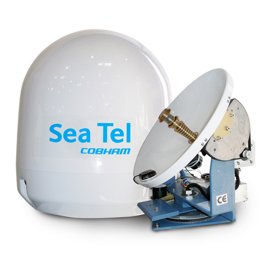
Sea Tel, Inc.
4030 Nelson Avenue
Concord, CA 94520
Tel: (925) 798-7979
Fax: (925) 798-7986
Email: seatel@seatel.com
Web:
www.seatel.com
February 21, 2006
COASTAL 18 SATELLITE TV RECEIVE-ONLY ANTENNA
Please record your Antenna Serial Number Here;
_______
Serial Number:
Look to the Leader. Look to Sea Tel.
INSTALLATION AN OPERATION
FOR SEA TEL MODEL
WITHOUT POLARIZATION
_______________
Sea Tel Europe
Unit 1, Orion Industrial Centre
Wide Lane, Swaythling
Southampton, UK S0 18 2HJ
Tel: 44 (0)23 80 671155
Fax: 44 (0)23 80 671166
Email: europe@seatel.com
Web:
www.seatel.com
Document. No. 124769
Revision A
Advertisement
Table of Contents

Related Manuals for Sea Tel COASTAL 18


Summary of Contents for Sea Tel COASTAL 18
- Page 1 Southampton, UK S0 18 2HJ Fax: (925) 798-7986 Tel: 44 (0)23 80 671155 Email: seatel@seatel.com Fax: 44 (0)23 80 671166 Web: www.seatel.com Email: europe@seatel.com Look to the Leader. Look to Sea Tel. Web: www.seatel.com February 21, 2006 Document. No. 124769 Revision A...
- Page 2 All Rights Reserved. The information contained in this document is proprietary to Sea Tel, Inc.. This document may not be reproduced or distributed in any form without the consent of Sea Tel, Inc. The information in this document is subject to change without notice.
- Page 4 Revision History ECO# Date Description February 17, 2006 Initial production release.
-
Page 5: Table Of Contents
Table of Contents 1. INTRODUCTION ..........................1-1 1.1. G ...................... 1-1 ENERAL YSTEM ESCRIPTION 1.2. P ............................1-1 URPOSE 1.3. S ........................1-1 YSTEM OMPONENTS 1.4. G ....................1-1 ENERAL SCOPE OF THIS MANUAL 1.5. Q ...................... 1-2 UICK VERVIEW OF CONTENTS 2. - Page 6 Table of Contents 3.3.4. Satellite Receivers ......................3-6 3.3.5. Television/Monitor ......................3-6 3.3.6. Matrix Switch ........................3-6 4. INSTALLATION ..........................4-1 4.1. S ..................... 4-1 ELECTION AND ABLE OUTING 4.2. E ....................4-2 QUIPMENT AND CABLE INSTALLATION 4.2.1. Cutouts & mounting holes ....................4-3 4.2.2.
- Page 7 Table of Contents 7. COASTAL 18 TECHNICAL SPECIFICATIONS ................. 7-1 7.1. I ......................... 7-1 NSTALLED EIGHT 7.2. R ............................7-1 ADOME 7.3. A ............................7-1 NTENNA 7.4. C LNB O ......................... 7-1 IRCULAR PTIONS 7.4.1. US Circular LNB....................... 7-1 7.4.2.
- Page 8 Table of Contents This Page Intentionally Left Blank viii...
-
Page 9: Introduction
1.4. General scope of this manual This manual describes the Sea Tel Coastal Antenna (also called the Above Decks Equipment), its operation and installation. Your system may contain other Below Deck Equipments which your dealer provided to you. Refer to the manuals for those equipments for their installation and operating instructions. -
Page 10: Quick Overview Of Contents
Introduction Coastal 18 Ku-Band TVRO 1.5. Quick Overview of contents The information in this manual is organized into chapters. Operation, basic system information, installation, setup, functional testing, maintenance, specifications and drawings relating to this TVRO Antenna are all contained in this manual... -
Page 11: Operation
Coastal 18 Ku-Band TVRO Operation Operation Detailed information on operating your Coastal Series antenna from the control panel is contained below. For quick reference information, please refer to the laminated card titled “Quick Start Operation” or the previous section. 2.1. -
Page 12: System Start-Up
Operation Coastal 18 Ku-Band TVRO 2.2. System Start-Up Normal operation begins by pressing the POWER key and waiting for the antenna to automatically acquire and track the desired satellite signal. After the system has been properly installed and set up, this initialization should take approximately 1 minute. -
Page 13: Tracking Phase
Coastal 18 Ku-Band TVRO Operation Search Wait - Indicates that a signal has been detected and the antenna is peaking the signal level. NID HHHH EL ## - Will be displayed whenever a satellite signal is found. This message is comprised of Network ID and the Elevation for the satellite being targeted or which satellite has been found. -
Page 14: Linear Polarization Adjustment
Operation Coastal 18 Ku-Band TVRO 2.4. Linear Polarization Adjustment Polarization is adjusted for a desired satellite when the system is initially installed. Subsequently it needs only to be adjusted when changing from one satellite to another, or when the boat has traveled a significant geographic distance. -
Page 15: Setting Polarization For A Different Satellite (Changing Satellites)
Coastal 18 Ku-Band TVRO Operation re-install the radome top. 2.4.2. Setting polarization for a different satellite (changing satellites) When changing from one satellite to another you may need to adjust the polarization of the LNB to be able to acquire the satellite you want to switch to. This will only be required if the difference in polarization angle of the two satellites is greater than ten degrees. -
Page 16: Loss Of Satellite Due To Blockage Or Rain-Fade
Operation Coastal 18 Ku-Band TVRO 2.5. Loss of satellite due to blockage or rain-fade If tracking is lost due to blockage or rain fade, the antenna will search until a signal is found which is high enough for the antenna to begin tracking. When the receiver interface is operating properly, the antenna will automatically continue searching until it has acquired the desired satellite. -
Page 17: Basic System Information
Coastal 18 Ku-Band TVRO Basic System Information Basic System Information This section provides you with some additional information about the satellites you will be using, basics of the your antenna system and other equipment within your system configuration. 3.1. Satellite Basics The Television Receive Only (TVRO) satellites are in orbit at an altitude of 22,753.2 Miles (36,600... -
Page 18: Satellite Footprints
These footprint charts show the locations where signal level is expected to be adequate for TV reception with your model antenna. Please note that while the coverage area information is believed to be correct, Sea Tel has no control over actual satellite operation, footprint coverage, or programming. The coverage maps are intended as a guide to reception and the actual coverage area and signal strength may vary. -
Page 19: Antenna Basics
Coastal 18 Ku-Band TVRO Basic System Information from you and how close you are to the Equator (refer to the polarization information in the Setup and the Operation sections of this manual). 3.2. Antenna Basics The following information is provided to explain some of the basic functions of the antenna: 3.2.1. -
Page 20: Stabilization
Basic System Information Coastal 18 Ku-Band TVRO 3.2.4. Stabilization Your antenna is a “stabilized” antenna. Stabilization is the process of de-coupling the ships’ motion from the antenna. Simply put, this allows the antenna to remain pointed at the satellite while the boat turns, rolls or pitches under it. -
Page 21: Components Of The System Configuration
Coastal 18 Ku-Band TVRO Basic System Information 3.3. Components of the System Configuration The following text provides a basic functional overview of the system components and component interconnection as referred to in the System Block Diagram for your model antenna (refer to the appropriate page which depicts your system configuration). -
Page 22: Power Supply
(RG-6 or BETTER is recommended) is connected from each matrix switch output to each satellite receiver. Sea Tel recommends that an ACTIVE Matrix be used in all installations. Matrix switches with 4, 8, 12, 16 or more outputs are available. -
Page 23: Installation
Installation of your Coastal Series Antenna system must be accomplished by or under the supervision of an authorized Sea Tel dealer for the Sea Tel Limited Warranty to be valid and in force. Good planning of the installation will provide the best results. Below is some guidance on issues that are important to consider when planning the installation. -
Page 24: Equipment And Cable Installation
Installation Coastal 18 Ku-Band TVRO airflow to prevent the receiver from over-heating and provide forced airflow if needed. At each receiver location, leave a sufficient length of cable to remove the receiver in order to access its rear panel without pulling connections off of the rear panel. -
Page 25: Cutouts & Mounting Holes
Coastal 18 Ku-Band TVRO Installation 4.2.1. Cutouts & mounting holes Using the radome template portion of drawing 118092, mark the mounting holes and cable passage cutout. Drill the mounting holes for the radome. A hole saw may be used to cut out the cable passage (for routing the cables into the base of the radome). - Page 26 Installation Coastal 18 Ku-Band TVRO Pass the coax and control cables through the hole in the radome base. Connect the antenna control cable and coax cables to the connectors provided on the bracket in the base of the radome. The coax...
- Page 27 Coastal 18 Ku-Band TVRO Installation Apply Loctite 241 (supplied) to the top of the four ¼” diameter x 4” long mounting studs and install the studs up into the threaded inserts in the antenna pedestal assembly from the underside of the radome base.
-
Page 28: Other System Cable Connections
Installation Coastal 18 Ku-Band TVRO Remove (cut) the Tiewraps that were used to immobilize the antenna pedestal assembly for shipping. Several are used for the elevation axis, one through a p-clamp in the dish clip and one around the azimuth yoke. -
Page 29: System Setup
Coastal 18 Ku-Band TVRO Installation Connect the antenna coaxes to the appropriate “LNB inputs” on the matrix switch. Connect each of the receiver coaxes to the receiver output connectors on the matrix switch. Connect each of the receiver coaxes to its respective satellite receiver “SATELLITE IN” connector. - Page 30 Installation Coastal 18 Ku-Band TVRO This Page Intentionally Left Blank...
-
Page 31: Setup
Coastal 18 Ku-Band TVRO Setup Setup 5.1. System Checkout Press the ON key on the antenna control panel. Both LED’s (TRACKING and UNWRAP) should illuminate for 5 seconds verifying the DC power and LED cable connections between the antenna control panel and the antenna pedestal assembly. -
Page 32: Setting Auto Threshold For Proper Tracking
Setup Coastal 18 Ku-Band TVRO 5.2.2. Setting Auto Threshold for Proper Tracking Auto Threshold needs to be set to about 1/3 of the difference in AGC between noise floor (OFF satellite) signal level and peak (ON satellite) signal level. The most common values used are 151for the 18, 161 for the 24 and 171 for the 30. - Page 33 Coastal 18 Ku-Band TVRO Setup If you do not want to edit any other sub-menu parameters, press SAVE again to exit the sub- menu and return to the SAT main menu display. From there you can press the M arrow key to go to next SAT numeric menu choice or to the Factory Settings menu choice.
- Page 34 Setup Coastal 18 Ku-Band TVRO Continue editing until all 4 digits have been set to the desired tracking Frequency for this satellite selection. Press the SAVE key to save the FREQ parameter for this SAT. If you want to edit any of the other default values that are loaded with preset, press the M arrow key to go to the next sub-menu parameter.
- Page 35 Coastal 18 Ku-Band TVRO Setup AUTO* Automatically scans through all the available forced * (star’ed) FEC rates. If the satellite does not generate an NID but does have a unique combination of FREQ, BAUD and FEC lock, select the appropriate FEC* choice from this list. The system will then generate its own unique forced NID to represent the desired satellite.
-
Page 36: Sat2 - Second Satellite Parameters
Setup Coastal 18 Ku-Band TVRO 5.2.3.9. POL TRIM Individual Polarization Trim offset adjustment to optimize the Auto-Polarization on this satellite. Some satellite beams aimed at certain geographic areas are purposely skewed in polarization. During initial setup of this satellite selection, you will have to trim/offset auto-polarization by the amount of skew of the satellite beam. -
Page 37: Sat5 - Fifth Satellite Parameters
Accessing the Factory Settings parameters should ONLY be done by a qualified technician from an authorized Sea Tel dealer. The Model Serial Number can be found on the blue and silver label below the reflector, on the blue frame of the pedestal. The parameters are: 5.2.9.1. -
Page 38: Linear Polarization Adjustment
Setup Coastal 18 Ku-Band TVRO 5.2.9.2. Serial Number This parameter sets Serial Number of the Antenna Pedestal into the PCU memory. The serial number starts with 98 followed by 6 digits that are editable. This parameter allows the Serial Number of the Antenna to be displayed on the Display Antenna Control Panel. -
Page 39: Optimizing The Polarization While On The Desired Satellite
Coastal 18 Ku-Band TVRO Setup but will NOT rotate the LNB. The antenna reports that it is tracking a good signal by displaying a steady (ON) TRACKING LED. If you determine that the satellite signal is not the desired satellite, press the NEXT key to search for the NEXT satellite signal. -
Page 40: Setting Polarization When You Have Changed Geographic Areas
Setup Coastal 18 Ku-Band TVRO Adjust polarization UP/DOWN the amount determined in step 2. Press NEXT to search for the next satellite. If the next satellite found is not the desired satellite, press NEXT to continue searching. Repeat searching until the desired satellite is found. Allow the antenna to track the satellite for about two minutes. -
Page 41: Operational System Checks
Coastal 18 Ku-Band TVRO Setup 5.5. Operational System Checks Check-out the antenna and other components of the system on the selected satellite. Assure that your TV(s) and satellite receiver(s) are set to view the Setup/Antenna/Signal Meter menu of the Satellite Receiver on the selected satellite (SAT 1-6). - Page 42 Setup Coastal 18 Ku-Band TVRO Figure 5-3 Display Antenna Control Panel – Setup Mode, page 1 5-12...
- Page 43 Coastal 18 Ku-Band TVRO Setup Figure 5-4 Display Antenna Control Panel – Setup Mode, page 2 5-13...
- Page 44 Setup Coastal 18 Ku-Band TVRO Figure 5-5 Display Antenna Control Panel – Setup Mode, page 3 5-14...
- Page 45 Coastal 18 Ku-Band TVRO Setup Figure 5-6 Display Antenna Control Panel – Setup Mode, page 4 5-15...
- Page 46 Setup Coastal 18 Ku-Band TVRO Figure 5-7 Display Antenna Control Panel – Setup Mode, page 5 5-16...
-
Page 47: Maintenance
_________________________________________ _________________________________________ Phone: ______________________ Fax: ____________________ Sea Tel can recommend local dealers that can provide service in your local area that can be contacted for assistance. You can contact us directly at either of the locations below; Sea Tel, Inc. -
Page 48: Preventive Maintenance
Maintenance Coastal 18 Ku-Band TVRO 6.3. Preventive Maintenance As needed - Clean the outside surface of the radome with warm soapy water to remove dust, grime and salt residue. There is no other preventive maintenance required 6.4. Fault Isolation/Trouble-shooting The following table is provided to help isolate problems in the Series Antenna system. -
Page 49: Pedestal & Pcu Troubleshooting Using Built-In Test (Bit)
Coastal 18 Ku-Band TVRO Maintenance Antenna doesn’t track any satellites 1. Assure that at least one receiver is ON (constantly searching) 2. Check for blockage 3. Assure correct starting elevation 4. May be out of satellite footprint 5. Check all coax cables for poor connection 6. -
Page 50: Dac Test
Maintenance Coastal 18 Ku-Band TVRO tests fails. If any test fails, replace the PCU and re-run BIT tests. 6.5.2. DAC Test This test checks the basic integrity of the Digital-to-Analog Converter on the PCU main board by looping back one of it’s outputs to the A/D. -
Page 51: Sensor Test
Coastal 18 Ku-Band TVRO Maintenance 6.5.6. Sensor Test This test checks for null sensor offsets for a level, motionless system. The checks have a fairly wide pass/fail criteria, but can still fail if pedestal is in motion or out of level more than a few degrees. -
Page 52: Replacing A Defective Lnb
Maintenance Coastal 18 Ku-Band TVRO center of it’s mechanical range. Loosen pot mounting bracket to de-couple the belt and rotate the pot sprocket. If the sprocket is loose on the shaft of the pot, tighten the set screws. If the pot does not rotate, replace it. - Page 53 Coastal 18 Ku-Band TVRO Maintenance Control Unit. If you replaced a linear LNB, re-optimize the polarization (refer to section 5.3). Verify that the LNB operating properly and resume normal operation.
- Page 54 Maintenance Coastal 18 Ku-Band TVRO This Page Intentionally Left Blank...
-
Page 55: Coastal 18 Technical Specifications
Coastal 18 Ku-Band TVRO Coastal 18 Technical Specifications Coastal 18 Technical Specifications 7.1. Installed Weight Coastal 18 General Assembly: Radome Assembly (dry*): 35 lbs. (15.6 kg) Total Weight (dry): *NOTE: 34” Radome panels can absorb up to 50% moisture by weight. -
Page 56: Koreasat Circular Lnb
Coastal 18 Technical Specifications Coastal 18 Ku-Band TVRO 7.4.2. KoreaSat Circular LNB Sea Tel Part Number: 116910-1 Type: Single output LNB Manufacturer: HET, but may vary RF Frequencies: 11.7 - 12.75 GHz IF Frequency: 950 - 2000 MHz LO Frequency: 11.750 GHz... -
Page 57: European Quad Universal Linear Lnb
+/- 15 degrees (implied) Elevation Pointing +/- 0 degrees of Roll Coastal 18, 24 & 30 = 15 to 70 degrees +/- 15 degrees of Roll Coastal 18 & 24 = 25 to 60 degrees Coastal 30 = 20 to 60 degrees +/- 25 degrees of Roll Coastal 18 &... -
Page 58: Pedestal Control Unit
Coastal 18 Technical Specifications Coastal 18 Ku-Band TVRO 7.7. Pedestal Control Unit Size 5 x 11 x 1.2 inches (12.7 x 27.9 x 3.05 cm) Features Fully integrated controller, sensors, motor drivers, and RF signal monitor. No external components. Connectors... -
Page 59: Power Requirements
Coastal 18 Ku-Band TVRO Coastal 18 Technical Specifications 7.9. Power Requirements Voltage 11-16 VDC normal operating range Current 3.0 Amps nominal @ 13.8 VDC Transient Protection Load Dump 60 volts Inductive coupling +/- 200v @ 1 uSec Reverse Battery Indefinite... -
Page 61: Computer Interface
Coastal 18 Ku-Band TVRO Computer Interface Computer Interface A computer can be connected to the antenna control panel to allow you to provide access to ALL the parameter settings of the query the Coastal Series antenna and view the responses it provides. The commands to set the parameters in the Coastal Series PCU are summarized below. -
Page 62: Communicating With The Coastal Series Pcu
The associated responses for each of the commands are shown below. An explanation for each group of characters in each response is included. While in Hyper Terminal, type in desired command key to query for desired responses: COMMAND SUMMARY - Coastal 18, 24, 32 Version 2.05e Monitor Function... - Page 63 Coastal 18 Ku-Band TVRO Computer Interface Control Function ↵ ↵ ↵ ↵ ^0080 Start bootloader. ↵ ↵ ↵ ↵ ^0086 Disable DACP updates and enter diagnostic test mode. ↵ ↵ ↵ ↵ ^0090 Reboot PCU. ↵ ↵ ↵ ↵ edddd Set elevation target to ddd.d degrees.
- Page 64 Computer Interface Coastal 18 Ku-Band TVRO This page left blank intentionally...
-
Page 65: Drawings
Coastal 18 Ku-Band TVRO Drawings DRAWINGS The following drawings are included with this manual for installation and maintenance reference. 9.1. Coastal 18 without Polarization Drawings Drawing Title 124764 System Coastal 18 Configuration Chart 124519_A General Assembly, Coastal 18 124518_A Pedestal Ass’y, Coastal 18 124517_A Antenna Ass’y, Coastal 18... - Page 66 Drawings Coastal 18 Ku-Band TVRO This page left blank intentionally...
- Page 67 124591 124735 124665-1 Coastal 18, Aussat 124764-002 124519-1 124736 20" 116715 Aussat dual linear 117508-11 124591 124735 124665-1 Coastal 18, US Linear 124764-003 124519-1 124736 20" 116715 dual linear 117508-2 124591 124735 124665-1 Coastal 18, Euro Quad 124764-004 124519-1 124736 20"...
- Page 68 DESCRIPTION REFERENCE DESIGNATOR 124869 SOFTWARE, COASTAL 18 PCU 124518-1 PEDESTAL ASS'Y, COASTAL 18 124517-1 ANTENNA ASS'Y, COASTAL 18, NO POL. 124651-1 HARNESS ASS'Y, INTERFACE, COASTAL S NOT SHOWN IN DWG (SEE REF DOC# 125011) 121966-2 GPS ANTENNA, RETERMINATED, 21.0 L...
- Page 69 APPROVED BY: TITLE: DASH DESCRIPTION ANGLES: GENERAL ASSEMBLY INTERPRET TOLERANCING PER ASME Y14.5M - 1994 WITH MOTORIZED POL MATERIAL: APPROVED DATE: COASTAL 18 WITHOUT MOTORIZED POL FINISH: SIZE SCALE: DRAWING NUMBER NOT TO SCALE 124519 3rd ANGLE COASTAL 18 1 OF 1...
- Page 70 SINGLE LEVEL MFG BILL OF MATERIAL FIND PART NO DESCRIPTION REFERENCE DESIGNATOR 124502-1 BASE SPINDLE/YOKE ASS'Y, COASTAL 18 124516-1 ELEVATION ASS'Y, COASTAL 18 121229 ENCLOSURE ASS'Y, 2-AXIS 110873-3 RF SPLITTER 125092 COUNTERWEIGHT, 2.28 LB 112573-2 TRIM WEIGHT, 1.17 LBS 108517-2 WEIGHT, TRIM 1.0 OZ...
- Page 71 Tel. 925-798-7979 Fax. 925-798-7986 X.XXX = .005 APPROVED BY: TITLE: ANGLES: PEDESTAL ASSSEMBLY INTERPRET TOLERANCING PER ASME Y14.5M - 1994 MATERIAL: APPROVED DATE: COASTAL 18 FINISH: SIZE SCALE: DRAWING NUMBER 124518 3rd ANGLE 1898 COASTAL 1 OF 1 FIRST USED:...
- Page 72 WASHER, FLAT, #4, S.S. 114590-144 SCREW, SOCKET SET-CUP, 6-32 x 1/4, S.S 114593-106 SCREW, SOCKET HD, 4-40 x 1/2, S.S. 114581-005 WASHER, LOCK, #4, S.S. ANTENNA ASS'Y, COASTAL 18, NO POL. PROD FAMILY EFF. DATE DRAWING NUMBER SHT 1 OF 1 COMMON 21-Feb-06...
- Page 73 REVISION HISTORY ECO# DESCRIPTION DATE NOTES: UNLESS OTHERWISE SPECIFIED 1. APPLY ADHESIVE PER SEATEL SPEC. 121730. NONE 02-21-06 RELEASED TO PRODUCTION, WAS X1 K.D.H. TORQUE THREADED FASTENERS PER SEATEL SPEC. 122305. DRAWN BY: TOLERANCES ALVARO UNLESS OTHERWISE SPECIFIED DRAWN DATE: 4030 NELSON AVENUE X.X = .050 07-05-05...
- Page 74 SINGLE LEVEL MFG BILL OF MATERIAL FIND PART NO DESCRIPTION REFERENCE DESIGNATOR 124519-2 GENERAL ASS'Y, COASTAL 18, DBS 124517-1 ANTENNA ASS'Y, COASTAL 18, NO POL. COMMENTS SEE COMMENTS SEE DASH TABLE 121229 ENCLOSURE ASS'Y, 2-AXIS 117043-5 HARNESS ASS'Y, INTERFACE 119205...
- Page 78 SHIELDED CONTROL CABLE ASSEMBLY 117230...
Need help?
Do you have a question about the COASTAL 18 and is the answer not in the manual?
Questions and answers