Table of Contents
Advertisement
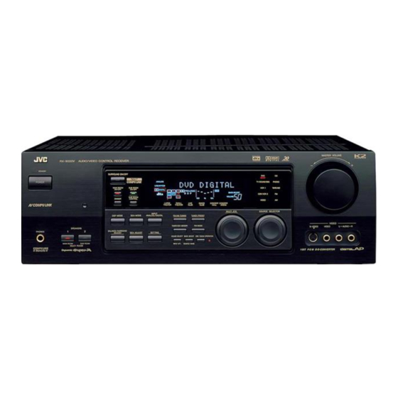
AUDIO/VIDEO CONTROL RECEIVER
RX-9000VBK
MAIN
SUB
STANDBY
ON
ROOM
ROOM
MAIN ROOM
SUB ROOM
TV/CATV/DBS
VCR 1
ON/OFF
ON/OFF
POWER
POWER
DVD
DVD MUILTI
CD
TAPE/MD
TV/DBS
VIDEO
PHONO
FM/AM
VCR 1
CDR/VCR 2 ANALOG/DIGITAL
SLEEP
SURROUND
CNTR TONE
CENTER
ON/OFF
1
2
3
MENU
MENU
REAR TONE
REAR-L
SURROUND
4
5
6
MODE
ENTER
ENTER
CD-DISC
SEA MODE
REAR-R
7
8
9
/P
SOUND
TEST
SUBWOOFER
10
0
+10
RETURN
FM MODE
100+
AUDIO/
TV/VCR
MENU
CATV/DBS
SET
TEXT
EXIT
STANDBY
DISPLAY
POWER
TV VOL
CHANNEL
VOLUME
TV/VIDEO
VCR 1
TAPE/MD
MUTING
CONTROL
/REW
PLAY
FF/
DOWN
TUNING
UP
REC
STOP
PAUSE
PHONES
COMPULINK
Remote
RM-SRX9000J
REMOTE CONTROL
RX-9000V
AUDIO/VIDEO CONTROL RECEIVER
SURROUND ON/OFF
MAIN ROOM
SUB ROOM
ON/OFF
ON/OFF
SUB ROOM
DIMMER
CONTROL
LARGE
SMALL
THEATER
THEATER
CLUB
INPUT
DSP MODE
SEA MODE
ANALOG/DIGITAL
FM/AM TUNING
TUNER/SEA MEMORY
SPEAKERS
BALANCE/SURROUND
1
2
SEA ADJUST
SETTING
ADJUST
SOUND SELECT
BASS BOOST ONE TOUCH OPERATION
INPUT ATT.
SOURCE NAME
MAIN ROOM
SUB ROOM
MULTI ROOM
INSTRUCTIONS
D I G I T A L
–
DVD
CD
TV SOUND/DBS
PHONO
VCR 1
TAPE/MD
CDR/VCR 2
FM
VIDEO
AM
LIVE
DANCE
CONCERT
CONCERT
CLUB
HALL
ARENA
MULTI JOG
SOURCE SELECTOR
TUNER PRESET
FM MODE
S-VIDEO
1 BIT P-E-M D-D-CONVERTER
MASTER VOLUME
+
VIDEO
VIDEO
L
AUDIO
R
D I G I T A L
For Customer Use:
Enter below the Model No. and Serial
No. which are located either on the rear,
bottom or side of the cabinet. Retain this
information for future reference.
Model No.
Serial No.
LVT0428-001A
[J]
Advertisement
Table of Contents

Subscribe to Our Youtube Channel
Related Manuals for JVC RX-9000VBK


Summary of Contents for JVC RX-9000VBK
- Page 1 AUDIO/VIDEO CONTROL RECEIVER RX-9000VBK MAIN STANDBY ROOM ROOM MAIN ROOM SUB ROOM TV/CATV/DBS VCR 1 ON/OFF ON/OFF POWER POWER DVD MUILTI TAPE/MD TV/DBS VIDEO PHONO FM/AM VCR 1 CDR/VCR 2 ANALOG/DIGITAL SLEEP SURROUND CNTR TONE CENTER ON/OFF MENU MENU REAR TONE...
- Page 2 Changes or modifications not expressly approved by the manufacturer for compliance could void the user’s authority to operate the equipment. Wall or obstructions RX-9000VBK JVC Americas Corp. 1700 Valley Road, Wayne New Jersey 07470 973-315-5000 cause harmful interference...
-
Page 3: Table Of Contents
Searching for a Disc (Only for the CD player) ... 51 Entering the Disc Information ... 52 AV COMPU LINK Remote Control System ... 54 Operating JVC’s Audio/Video Components ... 57 Operating Other Manufacturers’ Video Equipment ... 60 Troubleshooting ... 63 Specifications ... -
Page 4: Introduction
Introduction We would like to thank you for purchasing one of our JVC products. Before operating this unit, read this manual carefully and thoroughly to obtain the best possible performance from your unit, and retain this manual for future reference. -
Page 5: Parts Identification
Parts Identification Refer to the pages in parentheses for details. RX-9000V AUDIO/VIDEO CONTROL RECEIVER STANDBY SURROUND ON/OFF POWER MAIN ROOM ON/OFF DIMMER DSP MODE SPEAKERS BALANCE/SURROUND PHONES ADJUST MAIN ROOM SUB ROOM MULTI ROOM COMPULINK Remote MAIN ROOM ROOM STANDBY MAIN ROOM SUB ROOM TV/CATV/DBS... -
Page 6: Getting Started
Getting Started This section explains how to connect audio/video components and speakers to the receiver, and how to connect the power supply. Before Installation General • Be sure your hands are dry. • Turn the power off to all components. •... -
Page 7: Connecting The Speakers
AM Antenna Connections Snap the tabs on the loop into the ANTENNA slots of the base to assemble the AM loop. FM 75 COAXIAL LOOP AM Loop Antenna Outdoor single vinyl-covered wire (not supplied) Turn the loop until you have the best reception. Notes: •... -
Page 8: Connecting Audio/Video Components
Connecting the rear and center speakers Connect rear speakers to the REAR SPEAKERS terminals and a center speaker to the CENTER SPEAKER terminals. Center speaker CAUTION: SPEAKER IMPEDANCE CENTER REAR SPEAKER SPEAKERS Right rear speaker – LEFT RIGHT Connecting the subwoofer speaker You can enhance the bass by connecting a subwoofer. - Page 9 Cassette deck or MD recorder Cassette deck To audio input RIGHT LEFT PHONO (REC) TAPE (PLAY) MD recorder To audio input Note: You can connect either a cassette deck or an MD recorder to the TAPE/MD jacks. When connecting an MD recorder to the TAPE/MD jacks, change the source name, which will be shown on the display when selected as the source, to “MD.”...
- Page 10 Video camera The VIDEO input jacks on the front panel are convenient when connecting and disconnecting the equipment frequently. VIDEO S-VIDEO VIDEO AUDIO To audio output TV and/or DBS tuner When connecting the TV, DO NOT connect the TV’s video output to these video input terminals. RIGHT AUDIO RIGHT...
-
Page 11: Digital Connections
Digital connections This receiver is equipped with four DIGITAL IN terminals — one digital coaxial terminal and three digital optical terminals, and one DIGITAL OUT terminal. You can connect any digital equipment such as — • DBS tuner, • Digital TV broadcast tuner, •... -
Page 12: Setting Up The Rf Rod Antenna
Setting Up the RF Rod Antenna The RF rod antenna is supplied with this receiver to allow you to use the Multi-room function. With the RF rod antenna, you can operate the receiver at a distance of up to 50 feet (15 m) using the remote control. However, If the antenna cannot receive signals stably, you cannot operate the receiver correctly. -
Page 13: Putting Batteries In The Remote Control
Putting Batteries in the Remote Control Before using the remote control, put two supplied batteries first. 1. On the back of the remote control, remove the battery cover. 2. Insert batteries. Make sure to match the polarity: (+) to (+). 3. -
Page 14: Multi-Room Operations
Multi-room Operations Before operating this receiver any further, be familiar with this Multi-room function. This function enables you to listen to different sources in two different places (we call these two places “main room” and “sub-room”) by using this receiver only. This section explains only required speaker connections, the concept, and basic operations of the Multi-room function. -
Page 15: Basic Operating Procedure For Main Room
Basic Operating Procedure for Main Room On the front panel: 1. Press POWER. The STANDBY lamp on the front panel goes off, and the MAIN ROOM ON/OFF lamp on the front panel lights red. • For more details, “Turning the Power On and Off (Standby)” on page 15. -
Page 16: Basic Operating Procedure For Sub-Room
Basic Operating Procedure for Sub-Room The sources and functions available for the sub-room operations are limited. For more details on the sub-room operations, see “Sub-room Operations” on pages 20 to 22. On the front panel: 1. Press POWER. The STANDBY lamp on the front panel goes off, and the MAIN ROOM ON/OFF lamp on the front panel lights red. -
Page 17: Main Room Basic Operations
Main Room Basic Operations This section explains only the operations commonly used when you play any sound source in the main room. See pages 20 for the sub-room operations. IMPORTANT: When using the buttons and controls on the front panel: Check the following lamps’... -
Page 18: Selecting The Main Room Source To Play
To use this receiver for the main room operations again, press MAIN ROOM ON/OFF again. The MAIN ROOM ON/OFF lamp on the front panel lights red, and the currently selected Front speaker lamps on the front panel also light red. Notes: •... -
Page 19: Adjusting The Main Room Volume
Selecting different sources for picture and sound You can watch picture from a video component while listening to sound from another component. On the front panel: 1. Press SOUND SELECT (INPUT ATT.) briefly while viewing the picture from a video component such as the VCR or DVD player, etc. -
Page 20: Muting The Main Room Sound
Muting the Main Room Sound From the remote control ONLY: Press MUTING to mute the sound through all speakers in the main room and headphones connected. “MUTING” appears on the display and the volume turns off (the volume level indicator goes off). To restore the sound, press MUTING again so that “OFF”... -
Page 21: Adjusting The Front Speaker Output Balance
Adjusting the Front Speaker Output Balance If the sounds you hear from the front right and left speakers are unequal, you can adjust the speaker output balance in the main room. Before you start, remember... • There is a time limit in doing the following steps. If the setting is canceled before you finish, start from step 1 again. -
Page 22: Sub-Room Operations
Sub-Room Operations This section explains only the operations used when you play any sound source in the sub-room. See pages 15 for the main room operations. IMPORTANT: When using the buttons and controls on the front panel: Check the following lamps’ illumination. For the sub-room operations: •... -
Page 23: Canceling The Sub-Room Operations
Canceling the Sub-room Operations On the front panel: To stop the sub-room operations and sounds from the sub-room speakers, press SUB ROOM ON/OFF. The SUB ROOM ON/OFF lamp on the button goes off, and the SUB ROOM speaker (SPEAKERS 2) lamp and SUB ROOM CONTROL lamp on the front panel also go off (no sound will be heard in the sub-room). -
Page 24: Adjusting The Sub-Room Volume
LINK remote control system or the AV COMPU LINK remote control system, see pages 57 to 59. – If they are one of the JVC products, but not equipped with the above remote control systems, or if they are the products of the other manufacturers, see pages 60 to 62. -
Page 25: Basic Settings
Basic Settings Some of the following settings are required after connecting and positioning your speakers, while others will make operations easier. The following operations are only possible while the receiver is ready for the main room operations. IMPORTANT: When using the buttons and controls on the front panel: Check the following lamps’... -
Page 26: Setting The Speakers For The Dsp Modes
Setting the Speakers for the DSP Modes To obtain the best possible surround sound of the DSP modes, you have to register the information about the speakers arrangement after all connections are completed. Before you start, remember... • There is a time limit in doing the following steps. If the setting is canceled before you finish, start from step 1 again. - Page 27 2. Turn MULTI JOG to select the delay time of the rear speaker output. • Turn it clockwise to increase the delay time from 0 msec (“R. DELAY: 0ms”) to 15 msec (“R. DELAY: 15ms”). • Turn it counterclockwise to decrease the delay time from 15 msec (“R.
-
Page 28: Digital Input (Digital In) Terminal Setting
Digital Input (DIGITAL IN) Terminal Setting When you use the digital input terminals, you have to register what components are connected to which terminals (DIGITAL IN 1/2/3/ Before you start, remember... • There is a time limit in doing the following steps. If the setting is canceled before you finish, start from step 1 again. -
Page 29: Showing The Text Information On The Display
2. Press INPUT ANALOG/DIGITAL repeatedly until the digital input mode you want appears on the display. • Each time you press the button, the input mode changes as follows: AUTO/PCM ANALOG DIGITAL DTS DOLBY DIGITAL (Digital) (Digital) Normally select “AUTO/PCM,” so the receiver automatically detects the incoming digital signal format. -
Page 30: Storing The Basic Settings And Adjustments - One Touch Operation
Storing the Basic Settings and Adjustments — One Touch Operation JVC’s One Touch Operation function is used to assign and store different sound settings for each different main room source. By using this function, you do not have to change the settings every time you change the main room source. -
Page 31: Receiving Radio Broadcasts
Receiving Radio Broadcasts You can browse through all the stations or use the preset function to go immediately to a particular station. Indicates the functions YOU CAN ALSO USE when the receiver is ready for the sub-room operations. IMPORTANT: When using the buttons and controls on the front panel: Check the following lamps’... -
Page 32: Selecting The Fm Reception Mode
To tune in a preset station On the front panel: 1. Turn SOURCE SELECTOR to select the band (FM or AM). The last received station of the selected band is tuned in. 2. Press TUNER PRESET. 3. Turn MULTI JOG until you find the channel you want. -
Page 33: Using The Sea Modes
Using the SEA Modes The SEA (Sound Effect Amplifier) modes give you control of the way your music sounds. The following operations are only possible while the receiver is ready for the main room operations, and are only used for the main room sources. IMPORTANT: When using the buttons and controls on the front panel: Check the following lamps’... -
Page 34: Using The Dsp Modes
(bearing the mark ), or with DTS Digital Surround DOLBY SURROUND (bearing the mark ), you can use JVC Theater Surround. • When playing a source encoded with Dolby Surround (bearing the mark ), you can select “LARGE THEATER” or DOLBY SURROUND “SMALL THEATER.”... -
Page 35: Reproducing The Sound Field
The 3D-PHONIC mode is the result of research on sound localization technology carried out at JVC for many years. This mode can be used when the front speakers are connected to this receiver (without respect to the rear/center speaker connection). -
Page 36: Available Dsp Modes According To The Speaker Arrangement
Available DSP Modes According to the Speaker Arrangement Available DSP modes will vary depending on how many speakers are used with this receiver. Make sure that you have set the speaker information correctly (see page 24). Speaker arrangements Front speaker Center speaker Rear speaker... -
Page 37: Adjusting The Surround Modes
IMPORTANT: When using the buttons and controls on the front panel: Check the following lamps’ illumination. For the main room operations: • The MAIN ROOM ON/OFF lamp is lit. • The SUB ROOM CONTROL lamp is not lit. When using the remote control: Check to see if the multi-room operation selector and the remote control mode selector are set to the correct positions: •... - Page 38 To make the rear sounds softer, select “REAR SOFT 1” (a little) or “REAR SOFT 2” (much). When “REAR FLAT” is selected, no adjustment is applied. JVC Theater Surround adjustments Before you start, remember... MULTI JOG • Make sure that you have set the speaker information correctly (see page 24).
- Page 39 3) Repeat 1) and 2) to adjust the other speaker output levels. 3. Adjust the center tone. 1) Press BALANCE/SURROUND ADJUST repeatedly until “CENTER TONE” appears on the display. The display changes to show the current setting. 2) Turn MULTI JOG to select the center tone level you want.
-
Page 40: Adjusting The Dap Modes
Notes: • You can adjust the speaker output levels without outputting the test tone. • No test tone comes out of the center speaker when “CENTER SPK” is set to “NONE” (see page 24). • No test tone comes out of the rear speakers when “REAR SPK”... - Page 41 4. Adjust the overall level of the effects. 1) Press BALANCE/SURROUND ADJUST repeatedly until “EFFECT LEVEL” appears on the display. The display changes to show the current setting. 2) Turn MULTI JOG to select the effect level. • As you turn it, the effect level changes as follows: EFFECT 1 EFFECT 2...
-
Page 42: Activating The Dsp Modes
• Each time you press the button, the DSP modes change. (See page 34 for more details.) 2. Select and play a sound source. • To enjoy 3D-PHONIC and JVC Theater Surround, play back a software: – encoded with Dolby Surround and labeled with SURROUND ON/OFF –... -
Page 43: Using The Dvd Multi Playback Mode
Using the DVD MULTI Playback Mode This receiver provides the DVD MULTI playback mode for reproducing the analog discrete output mode of the DVD player. Before playing back a DVD, refer also to the manual supplied with the DVD player. The following operations are only possible while the receiver is ready for the main room operations, and are only used for the main room source —... -
Page 44: Using The On-Screen Menus
Using the On-Screen Menus You can use the Menus on the TV screen to control the receiver. To use this function, you need to connect the TV to the MONITOR OUT jack on the rear panel (see page 8), and set the TV’s input mode to the proper position to which the receiver is connected. -
Page 45: Adjusting The Front Speaker Output Balance
Adjusting the Front Speaker Output Balance (Also see page 19) 1. Press MENU. The MAIN MENU appears on the TV. • Pressing one of the % / fi / @ / # buttons also displays the MAIN MENU. 2. Press % / fi to move to “SOUND CONTROL,”... -
Page 46: Adjusting The Dvd Multi Playback Mode
“REAR L LEVEL”: Adjust the left rear speaker output level. ** “REAR R LEVEL”: Adjust the right rear speaker output level. ** For JVC Theater Surround (Large/small): “TEST TONE”: Output a test tone. “CENTER LEVEL”: Adjust the center speaker output level. -
Page 47: Selecting Your Favorite Sea Mode
Selecting Your Favorite SEA Mode (Also see page 31) 1. Press MENU. The MAIN MENU appears on the TV. • Pressing one of the % / fi / @ / # buttons also displays the MAIN MENU. 2. Press % / fi to move to “SOUND CONTROL,”... -
Page 48: Operating The Tuner
Operating the Tuner (Also see pages 29 and 30) 1. Press MENU. The MAIN MENU appears on the TV. • Pressing one of the % / fi / @ / # buttons also displays the MAIN MENU. 2. Press % / fi to move to “TUNER CONTROL,”... -
Page 49: Compu Link Remote Control System
COMPU LINK Remote Control System The COMPU LINK remote control system allows you to operate JVC audio components through this receiver. To use this remote control system, you need to connect JVC audio components through the COMPU LINK jacks (see below) in addition to the connections using cables with RCA pin plugs (see pages 6 and 7). -
Page 50: Synchronized Recording
Automatic Power Off (Standby): • When you turn off the receiver by pressing POWER, the connected components will turn off (standby). • When you turn off the main room sound by pressing MAIN ROOM ON/OFF, the selected main room source component turns off (unless the same component is selected as the sub-room source). -
Page 51: Text Compu Link Remote Control System
TEXT COMPU LINK Remote Control System The TEXT COMPU LINK remote control system has been developed to deal with the disc information recorded in the CD Text* and MDs. Using this information in the discs, you can operate the CD player or MD recorder equipped with the TEXT COMPU LINK remote control system through the receiver. -
Page 52: Showing The Disc Information On The Tv Screen
OPERATIONS To use this remote control system, you need to connect the TV to the MONITOR OUT jack on the rear panel (see page 8), and set the TV’s input mode to the proper position to which the receiver is connected. -
Page 53: Searching For A Disc (Only For The Cd Player)
Searching for a Disc (Only for the CD player) Search for a disc by its performer: 1. Press TEXT DISPLAY while “CD” is selected as the source. The Disc Information screen appears on the TV. 2. Press % / fi to move to “SEARCH,”... -
Page 54: Entering The Disc Information
Search for a disc by its genre: 1. Press TEXT DISPLAY while “CD” is selected as the source. The Disc Information screen appears on the TV. 2. Press % / fi to move to “SEARCH,” then press SET. The DISC SEARCH screen appears. - Page 55 4. Repeat step 3 until you finish putting a performer name (up to 32 characters). To insert a space, press % / fi / @ / # to move , then press SET. To correct an incorrect character: 1) Press % / fi / @ / # to move to + or =, then press SET until the incorrect character is selected.
-
Page 56: Av Compu Link Remote Control System
AV COMPU LINK Remote Control System The AV COMPU LINK remote control system allows you to operate JVC video components (TV, VCR, and DVD player) through the receiver. To use this remote control system, you need to connect the video components you want to operate, following the procedure below. - Page 57 • The IR signal transmitter can send signals at a distance of 10 feet (3 DVD player IR signal transmitter RX-9000VBK CASE2: If the components are not equipped with the S- video terminals DO NOT use these video terminals.
- Page 58 One-Touch DVD Play • Simply by starting playback on the DVD player, you can enjoy the DVD playback without setting other switches manually. The TV automatically turns on and changes the input mode to the position — “DVD (or DVD DIGITAL)” or “DVD MULTI” so that you can view the playback picture.
-
Page 59: Operating Jvc's Audio/Video Components
Operating JVC’s Audio/Video Components You can operate JVC’s audio and video components with this receiver’s remote control, since control signals for JVC components are preset in the remote control. IMPORTANT: To operate JVC’s audio components using this remote control: • You need to connect JVC audio components through the COMPU LINK-3 (SYNCHRO) jacks (see page 47) in addition to the connections using cables with RCA pin plugs (see pages 6 and 7). - Page 60 CD player-changer After pressing CD-DISC (with the remote control mode selector set to “AUDIO/TV/VCR”), you can perform the following operations on a CD player-changer: PLAY: Starts playing. Returns to the beginning of the current (or previous) track. ¢ ¢ : ¢...
- Page 61 COMPU LINK terminals (see page 54) in addition to the connections using cables with RCA pin plugs (see pages 7 and 8). • Some JVC VCRs can accept two types of the control signals — remote codes “A” and “B.” Before using this remote control, make sure that the remote control code of the VCR connected to the VCR 1 jacks is set to code “A.”...
-
Page 62: Operating Other Manufacturers' Video Equipment
4. Enter manufacturer’s code (two digits) using buttons 1–9, and 0. See the list on page 62 to find the code. Examples: For a JVC product, press 2, 8. For a Sanyo product, press 2, 5. 5. Release TV/CATV/DBS POWER. - Page 63 4. Enter manufacturer’s code (two digits) using buttons 1–9, and 0. See the list on page 62 to find the code. Examples: For a JVC product, press 1, 7. For an NEC product, press 3, 9. 5. Release VCR 1 POWER.
- Page 64 Manufacturers’ codes for the TV Aiwa 52, 53 Akai Bell & Howell Centurion Coronad Daewoo 35, 36, 41 Emerson 20, 21, 22, 23, 42 Fisher Fujitsu 54, 55 Funai 56, 57, 58, 59 02, 18, 49 GoldStar 30, 46 Hitachi 31, 32 28, 29, 60, 61 33, 34...
-
Page 65: Troubleshooting
Troubleshooting Use this chart to help you solve daily operational problems. If there is any problem you cannot solve, contact your JVC service center. PROBLEM The display does not light up. The buttons and controls on the front panel do not work. - Page 66 PROBLEM Continuous hiss or buzzing during FM reception. Occasional cracking noise during FM reception. No colors on the on-screen display. Howling during record playing. “OVERLOAD” starts flashing on the display. “TURN ON MAIN OR SUB ROOM” appears on the display. Remote control does not work.
-
Page 67: Specifications
Specifications Amplifier Output Power At Stereo operation: 120 W per channel, min. RMS, Front channels: driven into 8 , 20 Hz to 20 kHz with no more than 0.02% total harmonic distortion. 120 W per channel, min. RMS, driven into 4 , 20 Hz to 20 kHz with no more than 0.08% total harmonic distortion. - Page 68 Sophisticated electronic products may require occasional service. Just as quality is a keyword in the engineering and production of the wide array of JVC products, service is the key to maintaining the high level of performance for which JVC is world famous. The JVC service and engineering organization stands behind our products.
-
Page 69: Limited Warranty
WHAT WE WILL DO: If this product is found to be defective, JVC will repair or replace defective parts at no charge to the original owner. Such repair and replacement services shall be rendered by JVC during normal business hours at JVC authorized service centers. - Page 70 VICTOR COMPANY OF JAPAN, LIMITED 0200HIMMDWJEIN...
Need help?
Do you have a question about the RX-9000VBK and is the answer not in the manual?
Questions and answers