JVC RX-5032VSL Instructions Manual
Audio/video control receiver
Hide thumbs
Also See for RX-5032VSL:
- Instruction manual (244 pages) ,
- Instructions for use manual (141 pages) ,
- Instructions manual (87 pages)
Table of Contents
Advertisement
AUDIO/VIDEO CONTROL RECEIVER
RECEPTOR DE CONTROL DE AUDIO/VÍDEO
RECEPTOR DE COMANDO AUDIO/VÍDEO
RX-5032VSL
D I G I T A L
P R O L O G I C
RX-5030V
AUDIO/VIDEO CONTROL RECEIVER
INSTRUCTIONS
MANUAL DE INSTRUCCIONES
INSTRUÇÕES
TA/NEWS/INFO
DISPLAY MODE
For Customer Use:
Enter below the Model No. and Serial
No. which are located either on the rear,
bottom or side of the cabinet. Retain this
information for future reference.
Model No.
Serial No.
LVT0984-003A
[US]
Advertisement
Table of Contents

Related Manuals for JVC RX-5032VSL


Summary of Contents for JVC RX-5032VSL
- Page 1 AUDIO/VIDEO CONTROL RECEIVER RECEPTOR DE CONTROL DE AUDIO/VÍDEO RECEPTOR DE COMANDO AUDIO/VÍDEO RX-5032VSL RX-5030V AUDIO/VIDEO CONTROL RECEIVER D I G I T A L P R O L O G I C INSTRUCTIONS MANUAL DE INSTRUCCIONES INSTRUÇÕES TA/NEWS/INFO DISPLAY MODE For Customer Use: Enter below the Model No.
- Page 2 Warnings, Cautions, and Others/Avisos, precauciones y otras notas/ Advertêcias, precauções e outras notas/ Caution –– STANDBY/ON switch! Disconnect the mains plug to shut the power off completely. The STANDBY/ON switch in any position does not disconnect the mains line. The power can be remote controlled. Precaución ––...
- Page 3 Mantenha, além disso, a maior circulação de ar possível, como indica a ilustração. Spacing 15 cm or more Espacio de 15 cm o más Espaço de 15 cm ou mais RX-5032VSL Front Frente Frente Stand height 15 cm or more Allura del soporte 15 cm o más...
-
Page 4: Setting The Voltage Selector Switch
Before Installation Precautions General precautions • DO NOT insert any metal object into the unit. • DO NOT disassemble the unit or remove screws, covers, or cabinet. • DO NOT expose the unit to rain or moisture. Locations • Install the unit in a location that is level and protected from moisture. -
Page 5: Table Of Contents
Using Surround Modes ... 24 Using DSP Modes ... 25 COMPU LINK Remote Control System ... 26 AV COMPU LINK Remote Control System ... 27 Operating JVC’s Audio/Video Components ... 29 Operating Audio Components ... 29 Operating Video Components ... 31 Troubleshooting ... -
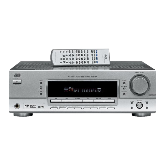
Page 6: Parts Identification
Parts Identification Front Panel 1 2 3 4 STANDBY SURROUND STANDBY/ON SURROUND/DSP PHONES D I G I T A L P R O L O G I C See pages in parentheses for details. 1 STANDBY/ON button and STANDBY lamp (10, 20) 2 SURROUND/DSP OFF button (24, 25) 3 DSP button (25) 4 SURROUND button (24) - Page 7 Parts Identification Remote Control A/V CONTROL RECEIVER TEST FRONT L CENTER MENU SURR L ENTER RETURN REC PAUSE TAPE/CDR FM/AM TV SOUND FM MODE SURROUND DIMMER TV/VIDEO VCR CH TV CH REMOTE CONTROL RM-SRX Rear Panel DIGITAL 1 (DVD) DIGITAL 2 ( CD ) (REC) TAPE /CDR...
-
Page 8: Getting Started
Getting Started Connecting the AM and FM Antennas AM antenna connection Connect the supplied AM loop antenna to the AM LOOP terminals. Turn the loop until you have the best reception. • If the reception is poor, connect an outdoor single vinyl- covered wire (not supplied) to the AM EXT terminal. -
Page 9: How To Connect Speaker Cords
Getting Started Connecting the Speakers and Subwoofer You can connect five speakers—a pair of front speakers, a center speaker, and a pair of surround speakers—and a subwoofer. CAUTION: Use speakers with a SPEAKER IMPEDANCE as indicated by the speaker terminals. 7 Connection diagram Cable with RCA pin plugs (not supplied) -
Page 10: Connecting Audio/Video Components
Getting Started Connecting Audio/Video Components Turn the power off to all components before making connections. You can connect the following audio/video components to this receiver. Refer also to the manuals supplied with your components. • Audio Components: CD player* and Cassette deck (or CD recorder*) •... - Page 11 Getting Started Video component connections Use cables with RCA pin plugs (not supplied). Connect the white plug to the audio left jack, the red plug to the audio right jack, and the yellow plug to the video jack. Rear panel (REC) TAPE /CDR...
-
Page 12: Digital Connections
Getting Started Digital Connections This receiver is equipped with two DIGITAL IN terminals—one digital coaxial terminal and one digital optical terminal. You can connect any component to one of the digital terminals using a digital coaxial cable (not supplied) or digital optical cable (not supplied). -
Page 13: Basic Operations
Basic Operations Front panel STANDBY/ON and STANDBY lamp RX–5032V AUDIO/VIDEO CONTROL RECEIVER Source selection buttons Turning On the Power Press STANDBY/ON (or STANDBY/ON remote control). The STANDBY lamp goes off. The name of the current source (or station frequency) appears on the display. To turn off the power (into standby mode) Press STANDBY/ON (or STANDBY/ON... -
Page 14: Selecting Different Sources For Picture And Sound
Basic Operations Front panel RX–5032V AUDIO/VIDEO CONTROL RECEIVER PHONES jack SPEAKERS Audio source ON/OFF selection buttons Selecting Different Sources for Picture and Sound You can watch the picture from a video component while listening to sound from another component. Press one of the audio source selection buttons while watching the picture from a video component such as the VCR or DVD player. -
Page 15: Turning Off The Sound Temporarily-Muting
Basic Operations After using the headphones Press SPEAKERS ON/OFF on the front panel to activate the speakers. The H.PHONE indicator goes off and the SPK indicator lights up. Disconnect the headphones. CAUTION: Be sure to turn down the volume • Before connecting or putting on headphones, as high volume can damage both the headphones and your hearing. -
Page 16: Basic Settings
Basic Settings Basic Settings Using MULTI JOG Dial After connecting and placing speakers, you need to make basic settings for the following items according to your listening conditions. • Speaker information (see the right column and page 14) • Digital input terminal sources (see page 14) 7 Operating buttons SETTING Buttons... -
Page 17: Selecting The Digital Input Terminals-Digital In
Basic Settings 7 Speaker distance—DISTANCE UNIT, FRNT (Front) DISTANCE, CNTR (Center) DISTANCE, SURR (Surround) DISTANCE Select the unit to measure the distance between your listening position and speakers—“METER” or “FEET.” After selecting the measuring unit, select the appropriate speaker distance for each speaker within the range of “0.3m” (“1FT”) to “9.0m”... -
Page 18: Selecting The Analog Or Digital Input Mode
Basic Settings Front panel RX–5032V AUDIO/VIDEO CONTROL RECEIVER D I G I T A L D I G I T A L P R O L O G I C S U R R O U N D Source selection buttons Selecting the Analog or Digital Input Mode... -
Page 19: Sound Adjustments
Sound Adjustments Front panel Attenuating the Input Signal When the input level of the analog source is too high, the sound will be distorted. If this happens, you need to attenuate the input signal level to prevent the distortion. Once this has been adjusted, this receiver memorizes the adjustment for each source. -
Page 20: Sound Adjustments Using Multi Jog Dial
Sound Adjustments Sound Adjustments Using MULTI JOG Dial You can adjust the sound using MULTI JOG dial on the front panel. • Tone—BASS, TREBLE • Subwoofer output level*—SUBWFR LEVEL • Speakers’ output level*— FRONT L/R LEVEL, CENTER LEVEL, SURR L/R LEVEL •... -
Page 21: Sound Adjustments Using Remote Control
Sound Adjustments 7 Tone—BASS, TREBLE Adjust the bass and treble sounds as you like (–10 dB to +10 dB in 2 step intervals). • “0” is the initial setting. 7 Subwoofer output level—SUBWFR (Subwoofer) LEVEL Adjust the subwoofer output level (–10 dB to +10 dB in 1 step intervals). -
Page 22: Adjusting Subwoofer Output Level
Sound Adjustments Press TEST. “TEST TONE L” starts flashing on the display and a test tone comes out of the speakers in the following order: TEST TONE L TEST TONE C (Left front speaker) (Center speaker) (Right front speaker) TEST TONE LS TEST TONE RS (Left surround speaker) (Right surround speaker) -
Page 23: Tuner Operations
Tuner Operations Front panel STANDBY/ON RX–5032V AUDIO/VIDEO CONTROL RECEIVER FM/AM FM/AM TUNING 5/∞ PRESET 5/∞ Setting the AM Tuner Interval Spacing Some countries space AM stations 9 kHz apart, and other countries use 10 kHz spacing. To select the 10 kHz interval: Be sure the receiver is turned off, but is plugged into an AC outlet. -
Page 24: Tuning In To A Preset Station
Tuner Operations Front panel RX–5032V AUDIO/VIDEO CONTROL RECEIVER FM/AM PRESET 5/∞ Press MEMORY again while the selected channel number is flashing on the display. The selected channel number stops flashing. The station is assigned to the selected channel number. Repeat steps 1 to 4 until you store all the stations you want. -
Page 25: Creating Realistic Sound Fields
Creating Realistic Sound Fields You can use the following Surround and DSP modes to reproduce a realistic sound field: Surround modes 7 Dolby • Dolby Pro Logic II • Dolby Digital 7 DTS Digital Surround DSP modes 7 DAP modes 7 All Channel Stereo Surround modes 7 Dolby... - Page 26 Creating Realistic Sound Fields DSP modes 7 DAP (Digital Acoustic Processor) modes DAP modes have been designed to create important acoustic surround elements. The sound heard in a live club, dance club, hall or pavilion consists of direct sound and indirect sound—early reflections and reflections from behind.
-
Page 27: Using Surround Modes
Creating Realistic Sound Fields Make sure that you have set the speaker information correctly (see pages 13 and 14). • If only the front speakers are connected, you cannot use Surround/DSP modes. • You cannot use DSP modes if no surround speakers are connected. •... -
Page 28: Using Dsp Modes
Creating Realistic Sound Fields Using DSP Modes Speaker layouts required for the DSP modes are as follows: • 5 channels (Front, center, and surround speakers are connected.) • 4 channels (Front and surround speakers are connected.) 7 Operating procedure Start playing 2 channel software—either analog or Linear PCM—and select the source. -
Page 29: Automatic Source Selection
The COMPU LINK remote control system allows you to operate JVC’s audio components through the remote sensor on the receiver. To use this remote control system, you need to connect JVC’s audio components through the COMPU LINK (SYNCHRO) jacks (see below) in addition to the connections using cables with RCA pin plugs (see page 7). -
Page 30: Av Compu Link Remote Control System
AV COMPU LINK Remote Control System The AV COMPU LINK remote control system allows you to operate JVC’s video components (TV, VCR, and DVD player) through the receiver. To use this remote control system, you need to connect the video components you want to operate following the diagrams and the procedure below. - Page 31 AV COMPU LINK Remote Control System The AV COMPU LINK remote control system allows you to use the five basic functions listed below. Remote Control of the TV, DVD player, and VCR using this Remote Control See page 31 for details. •...
-
Page 32: Operating Jvc's Audio/Video Components
IMPORTANT: To operate JVC’s audio components using this remote control: • You need to connect JVC’s audio components through the COMPU LINK (SYNCHRO) jacks (see page 26) in addition to the connections using cables with RCA pin plugs (see page 7). - Page 33 Operating JVC’s Audio/Video Components CD player After pressing CD, you can use the following buttons for the CD operations: Start playback. Return to the beginning of the current (or previous) tracks. ¢ Skip to the beginning of the next tracks.
-
Page 34: Operating Video Components
IMPORTANT: To operate JVC’s video components using this remote control: • You need to connect JVC’s video components through the AV COMPU LINK terminals (see page 27) in addition to the connections using cables with RCA pin plugs (see page 8). -
Page 35: Troubleshooting
Troubleshooting Use this chart to help you solve daily operational problems. If there is any problem you cannot solve, contact your JVC service center. PROBLEM The power does not come on. No sound from speakers. Sounds from speakers are heard unequally. -
Page 36: Specifications
Specifications Amplifier Output Power: Audio Audio Input Sensitivity/Impedance (1 kHz): Audio Input (DIGITAL IN)* : Audio Output Level: Signal-to-Noise Ratio (’66 IHF/DIN): Frequency Response (8 Ω): Tone Control: Video Video Input Sensitivity/Impedance: Composite video: Video Output Level/Impedance: Composite video: Synchronization: Signal-to-Noise Ratio: Designs &... - Page 37 Specifications FM tuner (IHF) Tuning Range: Usable Sensitivity: 50 dB Quieting Sensitivity: Signal-to-Noise Ratio (IHF-A weighted): Total Harmonic Distortion: Stereo Separation at REC OUT: Alternate Channel Selectivity: Frequency Response: AM tuner Tuning Range: Usable Sensitivity: Signal-to-Noise Ratio: General Power Requirements: Power Consumption: Dimensions (W x H x D): 87.50 MHz to 108.00 MHz...
- Page 38 Mains (AC) Line Instruction (not applicable for Europe, U.S.A., Canada, Australia and U.K.) Instrucción sobre la línea de la red (CA) (no aplicable para Europa, EE.UU., Canadá, Australia, ni el Reino Unido) Instrução sobre a tensão da rede eléctrica (CA) (não aplicável para a Europa, os E.U.A., o Canadá, a Austrália e o Reino Unido) CAUTION for mains (AC) line BEFORE PLUGGING IN, do check that your mains (AC) line...
Need help?
Do you have a question about the RX-5032VSL and is the answer not in the manual?
Questions and answers
JVC RX-5032VSL. Laite ei toimi, enkä osaa ratkaista ongelmaa. Käyttöohje minulla on. Oisko ukkonen rikkonut jotain. Ainut, mikä toimii, on äänen ohjaaminen telkasta em. laitteen kautta kajareihin.