Table of Contents
Advertisement
Quick Links
Advertisement
Table of Contents

Related Manuals for Calculated Industries 4087


Summary of Contents for Calculated Industries 4087
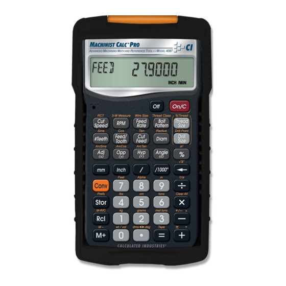
- Page 2 ACHINIST ™ The Machinist Calc™ Pro Advanced Machining Math and Reference Tool (Model 4087) provides fast, precise solutions for your every day machining calculations. With the Machinist Calc Pro you will spend less time looking up your most-needed calculations on charts, in books or on the Internet and more time machining.
-
Page 3: Table Of Contents
TAbLe Of CONTeNTS GeTTING STARTeD.....................5 KEY DEFINITIONS ....................5 Basic Function Keys ..................5 Dimensional Function Keys ................6 Weight and Volume Function Keys ..............7 Trigonometric Function Keys .................7 Miscellaneous Functions .................8 Machinist Function Keys .................9 SETTING FRACTIONAL RESOLUTIONS .............13 Permanently Set Fractional Resolution ............13 Temporarily Set Fractional Resolution ............14 PREFERENCE SETTINGS ................15 ENTERING DIMENSIONS ................16... - Page 4 RPM – Milling ....................26 RPM – Turning ....................27 RPM – Drilling ....................27 FEED RATE .....................28 Feed Rate – Based on Cutting Feed and RPM (for Turning) .......28 Feed Rate – Based on Cutting Feed and RPM (for Drilling) ......28 Feed Rate – Based on Feed per Tooth, RPM and # of Teeth ......29 CUTTING SPEED ....................30 Cutting Speed –...
- Page 5 Changing a Metric Thread Classification .............43 Numeric Thread Size ..................44 Fractional Thread Size ..................46 Metric Thread Size ..................47 Custom Thread Percentage ................48 WIRE SIzES AND 3-WIRE MEASUREMENTS ..........49 Wire Size .......................49 3-Wire Measurement – Known Thread Size and Wire Size ......50 Pitch Diameter –...
-
Page 6: Getting Started
GeTTING STARTeD You may want to practice getting a feel for your calculator keys by reading through the key definitions and learning how to enter data, how to store values, etc., before proceeding to the examples. KEY DEFINITIONS basic function Keys On/clear Key —... -
Page 7: Dimensional Function Keys
(cont’d) M- — Subtracts displayed value from Accumulative Memory. Dimensional function Keys Millimeters — Identifies entry as millimeters, with repeated presses toggling between linear, area and volume units. Converts dimensional value to units of millimeters, with repeated presses toggling between millimeters and meters. -
Page 8: Weight And Volume Function Keys
1/1000" (mils) — Multiplies a dimensionless entry by 0.001 Inch and displays the result as Inches. Converts a linear entry to decimal Inches. For both methods, the result is rounded and displayed to three decimal places Weight and Volume function Keys Tons —... -
Page 9: Miscellaneous Functions
(cont’d) Arccosine (Arccos) — Calculates the angle for the entered or calculated Cosine value. Tangent (Tan) — Calculates the Tangent of an entered degree or unitless value. Arctangent (ArcTan) — Calculates the angle for the entered or calculated Tangent value. Miscellaneous functions Degrees:Minutes:Seconds (dms◄►deg) —... -
Page 10: Machinist Function Keys
paperless Tape (Tape) — Accesses the Paperless Tape mode (see paperless Tape section), which keeps track of your past 30 entries. Useful for checking strings of numbers. preference Settings (prefs) — Accesses various customizable settings, such as dimensional answer formats (see preference Settings section). Machinist function Keys cutting Speed —... - Page 11 (cont’d) Feed rate — Enters or calculates Feed Rate. Unitless entries assumed inches per minute in U.S. mode; millimeters per minute in Metric mode. Calculates Feed Rate given values for Cutting Feed and RPM (Spindle Speed) or Feed per Tooth (Chip Load), RPM and Number of Teeth.
- Page 12 % Thread — Enters a non-standard Thread Grip Percentage for use in determining screw Tap Drill Sizes. Default value is 75%. Drill Size — Enters a numeric, letter, fractional or metric Drill Size, displaying the decimal Inch (U.S. mode) or millimeter (Metric mode) equivalent of the Drill Size.
- Page 13 (cont’d) Diameter — Enters a Diameter. Unitless entries assumed Inches in U.S. mode; millimeters in Metric mode. Calculates circle Area and Circumference given entered Diameter. Calculates Diameter given entered Radius. radius — Enters or calculates a Radius. Unitless entries assumed Inches in U.S. mode; millimeters in Metric mode.
-
Page 14: Setting Fractional Resolutions
Angle (θ) — Enters or calculates an Angle, providing the Adjacent Angle for both instances. Calculates an Angle given two other right- triangle values. Also enters the Starting Angle of the first hole of a Bolt Pattern, with 0° being the three o’clock position and the rotation going counterclockwise. -
Page 15: Temporarily Set Fractional Resolution
(cont’d) 3. To permanently set the Fractional Resolution you have selected above, press (or any key) to set the displayed Fractional Resolution and exit Preference Settings. KeySTROKe DISPLAy 4. To recall your selected Fractional Resolution: STD 0-1/64 INCH * 1/64" is the default setting. The display may differ from the example depending on what the resolution is currently set to. -
Page 16: Preference Settings
PrEFErENcE SETTINgS Press , then to access the Preferences menu. Continue pressing to toggle through different Preferences. Press keys to toggle between options of the different Preferences. Press to exit Preferences. Your calculator will keep your Preference Settings until a Full Reset alters your settings to the default values (see Appendix for more information). -
Page 17: Entering Dimensions
MATH CHAIn (repeats options) MATH OrDer ENTErINg DImENSIONS Note: Unlike other Calculated Industries/Construction Master calculators, the Machinist Calc Pro does not have a dedicated Feet key. Feet is a secondary function located above the key, so you have to use the key, then to enter or calculate dimensions using Feet. -
Page 18: Square And Cubic Dimensions
Square and Cubic Dimensions Examples of how square and cubic dimensions are entered (press after each entry): DIMeNSIONS KeySTROKe 14 square Inches 14 i i 11 square millimeters 11mm 1.5 cubic meters 1 .5g 9 9 9 3 cubic Feet 3 g 7g 7 g 7 cONvErSIONS Linear Conversions... - Page 19 (cont’d) KeySTROKe DISPLAy 9-1/2 15 g7 9 i 1 / 2 feeT INCH 15.791667 (Feet) feeT 9-1/2 feeT INCH Convert 17.32 Feet to Feet-Inch-Fractions: KeySTROKe DISPLAy 17.32 (Feet) 17 . 3 2 g7 feeT 3-27/32 = g7 feeT INCH 17.32 feeT 207.84 INCH...
-
Page 20: Square And Cubic Conversions
Square and Cubic Conversions Convert 6 square Feet to other square dimensions: KeySTROKe DISPLAy (Feet) 6g 7 g7 SQ feeT 557418.24 SQ MM 0.5574182 SQ M 5574.1824 (cm) SQ CM Convert 0.05 cubic meters to other dimensions: KeySTROKe DISPLAy 0.05 . -
Page 21: Weight Per Volume And Volume Conversions
Weight per Volume and Volume Conversions Convert 2 cubic Feet of stainless steel to pounds, tons, kilograms, and metric tons if the steel weighs 7,480 kilograms per cubic meter. KeySTROKe DISPLAy 1. Store the weight per volume: * (wt/vol) 7480. KG/ 7 4 8 0 S 0 0 0 0 CU M 2. -
Page 22: Multiplying Dimensions
KeySTROKe DISPLAy 2-1/2 6g72i1/2+ feeT INCH 7-3/4 11g75i1/4+ feeT INCH 1 8 . 2 5 i = feeT INCH 11-7/8 - 2 i 1/ 8 = feeT INCH Multiplying Dimensions Multiply 5 Feet 3 Inches by 11 Feet 6-1/2 Inches: KeySTROKe DISPLAy 5 g 7 3 i *... -
Page 23: Memory Operation
(cont’d) Find 18% of 50 Feet: KeySTROKe DISPLAy 50g7*18% feeT Take 20% from 17 Feet 6 Inches: KeySTROKe DISPLAy 1 7 g 76 i - 20 % feeT INCH mEmOrY OPEraTION Whenever the key is pressed, the displayed value will be added to the Memory. -
Page 24: Using Memory Storage Keys (M1- M9)
KeySTROKe DISPLAy M- 745. (M-) & 74 5 g M TOTAL - 135. & AVG - 45. & COUNT 3. & M+ - 135. Using Memory Storage Keys (M1- M9) In addition to the standard cumulative Memory (as previously described), your calculator has nine independent Storage Registers –... -
Page 25: Paperless Tape Operation
PaPErlESS TaPE OPEraTION The Paperless Tape allows you to display and review the last thirty entries of a regular math or basic dimensional math sequence. To access this mode after entering values, press . Then, press to scroll forward or backward through the entries. -
Page 26: Using The Machinist Calc Pro
KeySTROKe DISPLAy 11.5 7i1/2+ INCH 17.5 INCH 21.25 3i3 / 4 = INCH 2. Access the Tape function: TTL = 21.25 INCH 3. Scroll from first value to total: 01 4. INCH 02+ 7-1/2 INCH 03+ 6. INCH 04+ 3-3/4 INCH TTL = 21.25 INCH... -
Page 27: Rpm (Spindle Speed)
rPm (SPINDlE SPEED) RPM is the rotational speed of the spindle in revolutions per minute. In a milling machine or drill, the Spindle Speed is the rotation of the attached cutting tool. In a turning machine, it is the rotation of the attached workpiece. RPM can be calculated given values for Diameter and Cutting Speed. -
Page 28: Rpm - Turning
RPM – Turning Calculate the Spindle Speed (RPM) needed to turn a piece with a 5" Diameter at a recommended Cutting Speed of 650 sfm: KeySTROKe DISPLAy 1. Enter the bit Diameter: INCH 2. Enter the Cutting Speed: 650. 6 5 0 C feeT/MIN 3. -
Page 29: Feed Rate
FEED raTE Feed Rate is the speed of the cutting tool’s movement relative to the workpiece as the tool makes a cut. You can calculate Feed Rate given values for Cutting Feed and RPM (Spindle Speed). If you don’t know the Cutting Feed, you can calculate Feed Rate with Feed per Tooth (Chip Load), Number of Teeth and RPM. -
Page 30: Feed Rate - Based On Feed Per Tooth, Rpm And # Of Teeth
KeySTROKe DISPLAy 2. Enter the RPM: 8 0 0 R 800. 3. Calculate the Feed Rate: feeD 3.2000 INCH/MIN * Repeated presses of will toggle through the inputs and outputs, starting with the entered RPM (Spindle Speed). feed Rate – based on Feed per Tooth, rpM and # of Teeth Calculate the Feed Rate for a four-fluted end mill using a Feed per Tooth (Chip Load) of 0.005 Inch turning at 1,000 RPM (Spindle Speed):... -
Page 31: Cutting Speed
(cont’d) KeySTROKe DISPLAy 3. Enter the RPM: 1000. 1 0 0 0 R 4. Calculate the Feed Rate: feeD 20.0000 INCH/MIN 1000. 0.02 INCH/ReV * This Cutting Feed is calculated based on the entered Feed/Tooth and Number of Teeth. It, along with RPM, is then used to calculate the Feed Rate. -
Page 32: Cutting Speed - Turning
KeySTROKe DISPLAy 1250. 163.62462 feeT/MIN * The calculated Cutting Speed is displayed as a rounded, whole number value. displays the stored Cutting Speed value in decimal floating point format. Cutting Speed – Turning Calculate the Cutting Speed when turning a 4" rod at 300 RPM (Spindle Speed): KeySTROKe DISPLAy... -
Page 33: Cutting Speed - Using Metric Mode
(cont’d) KeySTROKe DISPLAy 2. Enter the RPM: 7 5 0 R 750. 3. Calculate the Cutting Speed: CUT 81. feeT/MIN * Repeated presses of will toggle through the inputs and outputs, starting with the entered Diameter. Cutting Speed – Using Metric Mode If you know you’re going to be making your calculations in metric units, you can easily set your calculator to Metric Mode prior to entering values. -
Page 34: Feed Per Tooth (Chip Load)
* Repeated presses of will toggle through the inputs and outputs, starting with the entered Diameter. FEED PEr TOOTH (cHIP lOaD) Feed per Tooth, or Chip Load, is the thickness of material removed by each cutting surface. You can calculate Feed per Tooth given values for Number of Teeth and Cutting Feed. -
Page 35: Feed Per Tooth - Based On Feed Rate, Rpm And # Of Teeth
feed per Tooth – based on Feed rate, rpM and # of Teeth Calculate Feed per Tooth (Chip Load) with a 12.8 Inch per minute Feed Rate, 4 Teeth and a Spindle Speed of 800 RPM: KeySTROKe DISPLAy 1. Enter the Feed Rate: feeD 12.8 1 2 . -
Page 36: Cutting Feed
KeySTROKe DISPLAy 0.006 6 B F INCH 2. Enter the Tool Diameter: INCH 3. Enter Cut Depth: (Cut Depth) DePTH . 1 gC INCH 4. Calculate the adjusted Feed per Tooth: ADJST 0 0100 INCH 5. Calculate the Radial Chip Thinning Factor: RCTf 1 6667 INCH... -
Page 37: Cutting Feed - Based On Feed Rate And Rpm
(cont’d) KeySTROKe DISPLAy 3. Calculate the Cutting Feed: CUT 0.0200 INCH/ReV 0.005 INCH TeeTH Cutting feed – based on Feed rate and rpM Calculate a Cutting Feed using a 15" Feed Rate and a Spindle Speed of 800 RPM: KeySTROKe DISPLAy 1. -
Page 38: Numeric Drill Size Entry
The selected Drill Size is displayed along with its decimal Inch equivalent. If the entered value doesn’t match a Drill Size, the next smaller size is displayed. You can toggle through the available sizes in increasing order with either the key or the key. -
Page 39: Inch Drill Size Entry
(cont’d) KeySTROKe DISPLAy 1. Enter Alpha Mode: (Alpha) ALPHA A 2. Toggle until the letter E is displayed: ALPHA e 8888 3. Enter as Drill Size: 0.2500 DRILL SIZe INCH 4. View next larger available sizes: 6_40 0.2520 MM DRILL SIZe INCH 6_50 0.2559... -
Page 40: Millimeter Drill Size Entry
KeySTROKe DISPLAy 1. Enter the 0.3" hole size and view next larger and next smaller sizes: 7_60 0.2992 .3iD MM DRILL SIZe INCH 0.3020 DRILL SIZe INCH 19/64 0.2969 DRILL SIZe INCH 2. Enter the 1" hole size and view next larger and next smaller sizes: 1.0000 DRILL SIZe... -
Page 41: Drill Point
DrIll POINT The Drill Point function calculates the Drill Point Cut Depth (length) of the stored Drill Size. By default, the calculation is based on a Cutting Angle of 118°. If a different Angle is desired, it can be stored using the Drill Point function (for example, stores 120°). -
Page 42: Internal Thread
Size. If the Thread Size you enter is not a standard size or if you have a non-common TPI/Pitch, you will need to directly enter the TPI/Pitch value, pressing after entering it in order to store the Thread Size. Both of these entry methods are covered in the examples provided within this section. -
Page 43: External Thread
(cont’d) external Thread Thread Size Minimum Pitch Diameter Cut Rod Size Maximum Major Diameter Roll Shank Size Minimum Major Diameter Maximum Pitch Diameter Maximum Minor Diameter Thread Classification With the Machinist Calc Pro you can choose between Internal and External Threads. Entering a U.S. Thread Size will allow you to choose among U.S. -
Page 44: Changing A U.s. Thread Classification
Changing a U.S. Thread Classification KeySTROKe DISPLAy ALL CLeARed 1. Recall the current Thread Classification: (Thread Class) INT 2b 2. Change to U.S. External Thread Class 2: eXT 2A 3. Change to U.S. External Thread Class 1: (Thread Class) eXT 1A 4. -
Page 45: Numeric Thread Size
(cont’d) KeySTROKe DISPLAy 3. Enter a Tolerance Grade of 6 and toggle through the available Tolerance Positions for the entered Grade: (Thread Class) * Repeated presses of will continue to toggle through the available Tolerance Positions of the specified Grade. Note: The number 3 can be entered to select both U.S. - Page 46 KeySTROKe DISPLAy 2. Enter the Thread Size: 8 – SIZe 3. Enter the TPI and store the final Thread Size: THReD 8 – 32 SIZe 4. Find the available Internal Thread characteristics: (Cut Tap Drill Size) DRILL SIZe R-TAP 3.75 (Roll Tap Drill Size) DRILL SIZe (Close Fit Drill Size)
-
Page 47: Fractional Thread Size
fractional Thread Size Find the available Internal and External Thread characteristics for a 1/4-28 screw. KeySTROKe DISPLAy ALL CLeARed 1. Verify Thread Class is set to 2B: INT 2b (Thread Class) 2. Enter the Thread Size: 1/4 – 1/4t SIZe INCH 3. -
Page 48: Metric Thread Size
KeySTROKe DISPLAy (Min. External Pitch Diameter) PTCH- 0.2225 SIZe INCH MAJR+ 0.2490 (Max. External Major Diameter) SIZe INCH (Min. External Major Diameter) MAJR- 0.2425 SIZe INCH (Max. External Minor Diameter) MINR+ 0.2065 SIZe INCH Metric Thread Size Find the available Internal and External Thread characteristics for a M5 x 0.75 screw with a Tolerance Class of 4H. -
Page 49: Custom Thread Percentage
(cont’d) KeySTROKe DISPLAy MAJR- 5.0000 (Min. Internal Major Diameter) SIZe 5. Switch to External 4g Tolerance Class and find the available External Thread characteristics: (Thread Class) THReD 5. – 0.75 SIZe 5.0000 (Rod Size for Thread Cutting) SIZe (Rod Size for Cold Forming) CfORM 4.4520 SIZe... -
Page 50: Wire Sizes And 3-Wire Measurements
KeySTROKe DISPLAy 2. Change the Thread Grip Percentage to 50% and calculate the new Cut Tap and Roll Tap Drill Sizes: (% Thread) THRD% 50gt SIZe THReD 1/4 – SIZe INCH (Cut Tap Drill Size) DRILL SIZe R-TAP * (Roll Tap Drill Size) DRILL SIZe * Repeated presses of will toggle through the inputs and outputs,... -
Page 51: 3-Wire Measurement - Known Thread Size And Wire Size
3-Wire Measurement – Known Thread Size and Wire Size You can find the Minimum and Maximum 3-Wire Measurements as well as the Pitch Diameters if you know the Thread Size and the Wire Size you want to use. Note: When solving for 3-Wire Measurements and Pitch Diameters, the calculator assumes the equivalent External Thread Type if an Internal Thread Type is set (i.e., Internal 2B is assumed External 2A for U.S. -
Page 52: Pitch Diameter - Known 3-Wire Measurement And Wire Size
KeySTROKe DISPLAy 8. Find the Maximum Pitch Diameter: PTCH+ 0.3331 SIZe INCH WIRe 0.04 SIZe INCH * If no Wire Size is entered, the calculated Ideal Wire Size will be used to find the 3-Wire Measurement. Pitch Diameter – Known 3-Wire Measurement and Wire Size You can also find the measured Pitch Diameter if you know the 3-Wire Measurement and the Wire Size used to obtain the measurement. -
Page 53: Bolt Pattern
(cont’d) KeySTROKe DISPLAy 6. Find the Pitch Diameter: P-DIA 0.3316 SIZe INCH WIRe 0.04 SIZe INCH * If no Wire Size is entered, the calculated Ideal Wire Size will be used to find the Pitch Diameter. BOlT PaTTErN With the Machinist Calc Pro, you can determine a Bolt Pattern by entering the Bolt Circle Diameter, the Number of Bolt Holes and the Angle of the first bolt hole (optional). - Page 54 KeySTROKe DISPLAy 1 0 ia INCH 2. Enter the Center y-coordinate: 1 5 ip INCH 3. Enter the Start Angle: ANGLe 20.° 20 n 4. Enter Bolt Circle Diameter: 3. 5 d INCH 5. Enter the Number of Bolts: bOLTS 6.
-
Page 55: Right Triangle Functions
rIgHT TrIaNglE FuNcTIONS With the Machinist Calc Pro, you can easily solve Right Triangle problems by simply entering two of four variables: Adjacent, Opposite, Hypotenuse or Angle. Right Triangle – based on Adjacent and Opposite Legs Calculate the Hypotenuse, Angle and Adjacent Angle of a right triangle with an Adjacent Leg of 3 Inches and an Opposite Leg of 4 Inches: Opposite Hypotenuse... -
Page 56: Right Triangle - Based On Hypotenuse And Angle
Right Triangle – based on hypotenuse and Angle Calculate the Adjacent Angle, Adjacent Leg and Opposite Leg of a right triangle with a Hypotenuse of 12 Inches and a known Angle of 35.34°: KeySTROKe DISPLAy 1. Enter the Hypotenuse: 12ih INCH 2 Enter the known Angle: ANGLe... -
Page 57: Circumference And Area - Based On Radius
Circumference and Area – based on radius Find the Diameter, Area and Circumference of a circle with a Radius of 3-1/4 Inches: KeySTROKe DISPLAy 3-1/4 (Radius) 3i1/4gd INCH 6-1/2 INCH AReA 33.1831 SQ INCH CIRC 20-27/64 INCH BaSIc D:m:S aND TrIgONOmETrY ExamPlES Converting Degrees:Minutes:Seconds Convert 23°... -
Page 58: Trigonometric Functions
KeySTROKe DISPLAy DMS 7.45.33° 7.45.33+ DMS 19.01.53° 11.16.20= Trigonometric functions The following drawing and formulas list basic trigonometric formulas, for your reference: Given side A and angle a, find: Side C (Cos) (e.g., (Cos) 3i,53.13gF Side B (Tan) Angle b 90°... -
Page 59: Appendix A - Default Settings
(cont’d) Given side C and angle a, find: Side A (Cos) Side B (Sine) Given side A and side C, find: Angle a (ArcCos) Angle b (ArcSine) Given side B and angle b, find: Side C (Cos) Side A (Tan) APPeNDIX A –... -
Page 60: Appendix B - Preference Settings
PRefeReNCe SeTTINGS DefAULT VALUe Volume Answer Format Standard Fractional Mode Standard Mathematical Operation Order of Operations Method * Depressing the Reset button located above the key will also perform a Full Reset. APPeNDIX b – prEFErENcE SETTINGS The Machinist Calc Pro has Preference Settings that allow you to customize or set desired unit formats and calculations. - Page 61 (cont’d) – 0.0000: calculation results using Machin- 2) Functional ist functions are displayed to four decimal Result places. Rounding – 0.000: calculation results using Machinist functions are displayed to three decimal places. – fLOAT: calculation results using Machinist functions are always displayed to the maxi- mum number of decimal places.
- Page 62 – Standard: if units entered are the same 5) Volume – e.g., Feet x Feet x Feet – the answer will Answer remain in this format (Cubic Feet), but if units Format entered are different – e.g., Feet x Feet x Inches –...
-
Page 63: Appendix C - Care Instructions
APPeNDIX C – cArE INSTrUcTIONS Please follow the guidelines listed in this section for proper care and operation of your calculator. Not following the instructions listed below may result in damage not covered by your warranty. Refer to the WArrANTy section on page 69 for more details. -
Page 64: Auto Shut-Off
Note: Please use caution when disposing of your old batteries, as they contain hazardous chemicals. Replacement batteries are available at most discount or electronics stores. You may also call Calculated Industries at 1-775-885-4900. battery Replacement Instructions To replace the batteries, slide open the battery door (at top backside of unit) and replace with new batteries. -
Page 65: Repair And Return
RePAIR AND ReTURN rETurN guIDElINES Please read the Warranty in this User’s Guide to determine if your Calculated Industries product remains under warranty before calling or returning any device for evaluation or repairs. If your product won’t turn on, check the batteries as outlined in the User’s Guide. -
Page 66: Warranty
Non-warranty repair covers service beyond the warranty period, or service requested due to damage resulting from misuse or abuse. Contact Calculated Industries at the number listed above to obtain current product repair information and charges. Repairs are guaranteed for 90 days. - Page 67 Disclaimer CI MAKES NO WARRANTY OR REPRESENTATION, EITHER ExPRESS OR IMPLIED, WITH RESPECT TO THE PRODUCT’S QUALITY, PERFORMANCE, MERCHANTABILITY, OR FITNESS FOR A PARTICULAR PURPOSE. AS A RESULT, THIS PRODUCT, INCLUDING BUT NOT LIMITED TO, KEYSTROKE PROCEDURES, MATHEMATICAL ACCURACY AND PREPROGRAMMED MATERIAL, IS SOLD “AS IS,”...
- Page 68 Legal Notes Software copyrighted and licensed to Calculated Industries by Specialty Calculator Technologies, LLC, 2011. User’s Guide copyrighted by Calculated Industries, Inc., 2011. Machinist Calc™ Pro is a trademark and Calculated Industries is a ® registered trademark of Calculated Industries, Inc. © 2011.
- Page 69 4840 Hytech Drive Carson City, NV 89706 U.S.A. 1-800-854-8075 • Fax: 1-775-885-4949 E-mail: info@calculated.com www.calculated.com...
Need help?
Do you have a question about the 4087 and is the answer not in the manual?
Questions and answers