Table of Contents
Advertisement
Quick Links
Advertisement
Table of Contents

Subscribe to Our Youtube Channel
Related Manuals for Calculated Industries Machinist Calc 4086


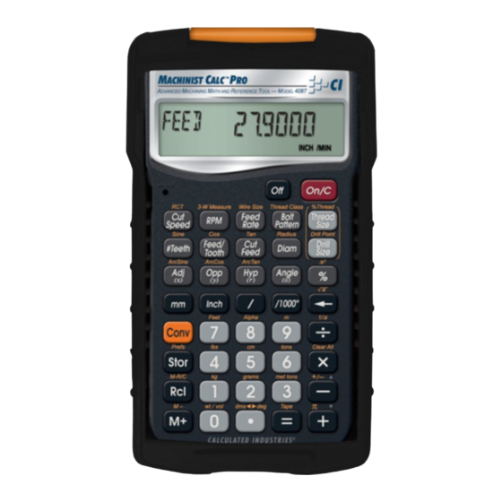
Summary of Contents for Calculated Industries Machinist Calc 4086
- Page 2 ACHINIST ™ ACHINIST ™ The Machinist Calc™ Machining Math and Reference Tool (Model 4086) and the Machinist Calc™ Pro Advanced Machining Math and Reference Tool (Model 4087) both provide fast, precise solutions for your every day machining calculations. With the Machinist Calc/ Machinist Calc Pro you will spend less time looking up your most- needed calculations on charts, in books or on the Internet and more time machining.
-
Page 3: Table Of Contents
TAbLe Of CONTeNTS GeTTING STARTeD ..................5 KEY DEFINITIONS ..................5 Basic Function Keys ..................5 Dimensional Function Keys ................ 6 Weight and Volume Function Keys ............. 7 Trigonometric Function Keys ......7 (NOT AVAILABLE ON MODEL 4086) Miscellaneous Functions ................8 Machinist Function Keys ................ - Page 4 CUTTING SPEED ..................25 Cutting Speed – Milling ................26 Cutting Speed – Turning ................26 Cutting Speed – Drilling ................27 Cutting Speed – Using Metric Mode ............27 RPM (SPINDLE SPEED) ................28 RPM – Milling .................... 28 RPM –...
- Page 5 Changing a U.S. Thread Classification ............. 46 Changing a Metric Thread Classification ..........46 Numeric Thread Size – Model 4087 ............47 Fractional Thread Size – Model 4087 ............48 Metric Thread Size – Model 4087 ............. 50 Custom Thread Percentage ......
-
Page 6: Getting Started
GeTTING STARTeD You may want to practice getting a feel for your calculator keys by reading through the key definitions and learning how to enter data, how to store values, etc., before proceeding to the examples. KEY DEFINITIONS basic function Keys On/Clear Key —... -
Page 7: Dimensional Function Keys
Dimensional function Keys Millimeters — Identifies entry as millimeters, with repeated presses toggling between linear, area and volume units. Converts dimensional value to units of millimeters, with repeated presses toggling between millimeters and meters. Centimeters (cm) — Identifies entry as centimeters, with repeated presses toggling between linear, area and volume units. -
Page 8: Weight And Volume Function Keys
Weight and Volume function Keys Tons — Enters or converts a weight or volume value to tons. Pounds (lbs) — Enters or converts a weight or volume value to pounds. Metric Tons (met tons) — Enters or converts a weight or volume value to metric tons. Grams —... -
Page 9: Miscellaneous Functions
(cont'd) Arctangent (ArcTan) — Calculates the angle for the entered or calculated Tangent value. Miscellaneous functions Degrees:Minutes:Seconds (dms◄►deg) — Converts between D:M:S and decimal degree formats; repeated presses will toggle between the two formats. Percentage — Used to find a given percent of a number. -
Page 10: Machinist Function Keys
Preference Settings (Prefs) — Accesses various customizable settings, such as dimensional answer formats (see Preference Settings section). Machinist function Keys Cutting Speed — Enters or calculates Cutting Speed. Unitless entries assumed feet per minute in U.S. mode; meters per minute in Metric mode. Calculates Cutting Speed given entered Diameter and RPM (Spindle Speed). - Page 11 (cont'd) Wire Size — Enters or calculates Wire Size for 3-Wire Measurements. Unitless entries assumed Model 4087 Inches in U.S. mode; millimeters in Metric mode. only Calculates the recommended Best (Ideal), Maximum and Minimum Wire Sizes given an entered Thread Size.
- Page 12 Drill Size — Enters a numeric, letter, fractional or metric Drill Size, displaying the decimal Inch equivalent of the Drill Size. The next smaller Drill Size is displayed if the entered value doesn’t match a Drill Size. Repeated presses of toggle through Drill Sizes in increasing order.
- Page 13 (cont'd) Radius — Enters or calculates a Radius. Calculates Radius given entered Diameter. Model 4087 only Alpha — Enters alphabet character selection mode. While in this mode, a letter can be selected and used with to enter a letter Drill Size. Entering this mode with a unitless entry between 1 and 26 will display the corresponding letter of the alphabet (i.e.
-
Page 14: Setting Fractional Resolutions
SETTINg FracTIONal rESOluTIONS The Machinist Calc and Machinist Calc Pro are set to display fractional answers in 64ths of an Inch. All examples in this User’s Guide are based on 1/64”. However, you may select Fractional Resolution to be displayed in other formats (e.g., 1/16”, 1/32”, etc.). The methods for permanently and temporarily changing Fractional Resolution are shown in the following sections. -
Page 15: Temporarily Set Fractional Resolution
Temporarily Set fractional Resolution You can also convert a fractional value to a different resolution temporarily while solving a problem. In the example below, add 1/64th to 44/64th of an Inch and then convert the answer to other Fractional Resolutions: KeYSTROKe DISPLAY 0-44/64... - Page 16 KeYSTROKe DISPLAY (Prefs) g S S f-RND 0.0000 (Functional Result Rounding) f-RND 0.000 f-RND fLOAT (repeats options) f-RND 0.0000 Third press of (Default Unit Format) US UnITS MeTRC UnITS (repeats options) US UnITS Fourth press of AReA Std. (Area Answer Format) AReA 0.
-
Page 17: Entering Dimensions
ENTErINg DImENSIONS Note: Unlike other Calculated Industries/Construction Master calculators, the Machinist Calc and Machinist Calc Pro do not have a dedicated Feet key. Feet is a secondary function located above the key, so you have to use the key, then to enter or calculate dimensions using Feet. -
Page 18: Square And Cubic Dimensions
Square and Cubic Dimensions Examples of how square and cubic dimensions are entered (press after each entry): DIMeNSIONS KeYSTROKe 14 square Inches 1 4 i i 11 square millimeters 11m m 1.5 cubic meters 1 . 5g 9 9 9 3 cubic Feet 3 g 7 g 7 g 7 cONvErSIONS... - Page 19 (cont'd) Convert 15 Feet 9-1/2 Inches to decimal Feet. Then convert back to Feet-Inch-Fractions. KeYSTROKe DISPLAY 9-1/2 1 5 g 7 9 i 1 / 2 feeT INCH (Feet) 15.791667 feeT 9-1/2 feeT INCH Convert 17.32 Feet to Feet-Inch-Fractions: KeYSTROKe DISPLAY 17.32 (Feet)
-
Page 20: Square And Cubic Conversions
Square and Cubic Conversions Convert 6 square Feet to other square dimensions: KeYSTROKe DISPLAY (Feet) 6 g 7 g 7 SQ feeT 557418.24 SQ MM 0.5574182 SQ M (cm) 5574.1824 SQ CM Convert 0.05 cubic meters to other dimensions: KeYSTROKe DISPLAY 0.05 .0 5 g 9 9 9... -
Page 21: Basic Math Operations
(cont'd) KeYSTROKe DISPLAY 1. Store the weight per volume: * (wt/vol) 7480. KG/ 7 4 8 0S 0 00 0 CU M 2. Enter steel volume: 2 g 7 g 7 g 7 CU feeT 3. Convert to pounds, tons, kilograms and metric tons: (lbs) 933.92229 (tons) -
Page 22: Multiplying Dimensions
Multiplying Dimensions Multiply 5 Feet 3 Inches by 11 Feet 6-1/2 Inches: KeYSTROKe DISPLAY 5 g 7 3 i * feeT INCH 60.59375 1 1g 7 6 i 1 / 2 = SQ feeT Multiply 2 Feet 7 Inches by 10: KeYSTROKe DISPLAY 2 g 7 7 i * 1 0 =... -
Page 23: Memory Operation
(cont'd) KeYSTROKe DISPLAY 1 7 g 7 6 i- 2 0 % feeT INCH mEmOrY OPEraTION Whenever the key is pressed, the displayed value will be added to the Memory. Other Memory functions: fUNCTION KeYSTROKe Add to Memory Subtract from Memory Recall total in Memory Display/Clear Memory Clear Memory... -
Page 24: Using Memory Storage Keys (M1- M9)
Using Memory Storage Keys (M1- M9) In addition to the standard cumulative Memory (as previously described), your calculator has nine independent Storage Registers – M1 through M9 – that can be used to permanently store single, noncumulative values. The following example shows the use of M1 ( ). - Page 25 (cont'd) While in the Paperless Tape mode, the display will show the previously entered or calculated value, along with the sequential number of the entry (e.g., 01, 02, 03, etc.) and the math operator (+, –, x, ÷, %) in the upper left corner of the display.
-
Page 26: Using The Machinist Calc/Machinist Calc Pro
KeYSTROKe DISPLAY 3. Scroll from first value to total: 01 4 INCH 02+ 7-1/2 INCH 03+ 6 INCH 04+ 3-3/4 INCH TTL = 21-1/4 INCH 4. Scroll last two values: 04+ 3-3/4 INCH 03+ 6 INCH 5. Exit Tape function and add another value to your total: TTL = 21-1/4 INCH 21-1/4... -
Page 27: Cutting Speed - Milling
(cont'd) Cutting Speed – Milling Calculate the Cutting Speed for a mill using a 1/2” tool running at 1,250 RPM (Spindle Speed): KeYSTROKe DISPLAY 1. Enter the Diameter of the tool: 0-1/2 1 / 2 d INCH 2. Enter the RPM: 1250. -
Page 28: Cutting Speed - Drilling
* Repeated presses of will toggle through the inputs and outputs, starting with the entered Diameter. Cutting Speed - Drilling Calculate the Cutting Speed using a 10.5 mm drill bit with the Spindle Speed set to 750 RPM: KeYSTROKe DISPLAY 1. -
Page 29: Rpm (Spindle Speed)
(cont'd) KeYSTROKe DISPLAY 3. Store as the Diameter: 0.228 INCH 4. Enter the RPM: 750. 7 5 0 R 5. Calculate the Cutting Speed: CUT 14. M/MIN 6. Return calculator to U.S. Mode: US UnITS g S S S + * Repeated presses of will toggle through the inputs and outputs, starting with the entered Diameter. -
Page 30: Rpm - Turning
KeYSTROKe DISPLAY 1. Enter the bit Diameter: 0-3/8 3/8 d INCH 2. Enter the Cutting Speed: 300. 30 0C feeT/MIN 3. Calculate the Spindle Speed (RPM): RPM 3056. 300. feeT/MIN 0-3/8 INCH 3055.7749 * The calculated RPM is displayed as a rounded, whole number value. displays the stored RPM value in decimal floating point format. -
Page 31: Rpm - Drilling
RPM - Drilling Calculate what the RPM (Spindle Speed) should be set to when drilling into material with a recommended Cutting Speed of 90 sfm using a 5/8” bit: KeYSTROKe DISPLAY 1. Enter the Diameter: 0-5/8 5 / 8 d INCH 2. -
Page 32: Feed Per Tooth - Based On Feed Rate, Rpm And # Of Teeth
KeYSTROKe DISPLAY 2. Enter the Number of Teeth: TeeTH 3. Calculate the Feed per Tooth: fPT 0.0060 INCH TeeTH 0.024 INCH/ReV feed per Tooth – Based on Feed Rate, RPM and # of Teeth Calculate Feed per Tooth (Chip Load) with a 12.8 Inch per minute Feed Rate, 4 Teeth and a Spindle Speed of 800 RPM: KeYSTROKe DISPLAY... -
Page 33: Cutting Feed - Based On Feed Per Tooth And # Of Teeth
(cont'd) Cutting feed – Based on Feed per Tooth and # of Teeth Calculate Cutting Feed with a Feed per Tooth (Chip Load) of 0.005 Inch and 4 Teeth: KeYSTROKe DISPLAY 1. Enter the Feed per Tooth: 0.005 .0 0 5 F INCH 2. -
Page 34: Feed Rate
FEED raTE Feed Rate is the speed of the cutting tool’s movement relative to the workpiece as the tool makes a cut. You can calculate Feed Rate given values for Cutting Feed and RPM (Spindle Speed). If you don’t know the Cutting Feed, you can calculate Feed Rate with Feed per Tooth (Chip Load), Number of Teeth and RPM. -
Page 35: Feed Rate - Based On Feed Per Tooth, Rpm And # Of Teeth
(cont'd) KeYSTROKe DISPLAY 1. Enter the Cutting Feed: .0 0 4c 0.004 INCH/ReV 2. Enter the RPM: 8 0 0 R 800. 3. Calculate the Feed Rate: feeD 3.2000 INCH/MIN * Repeated presses of will toggle through the inputs and outputs, starting with the entered RPM (Spindle Speed). -
Page 36: Drill Sizes
KeYSTROKe DISPLAY 1000. 1 0 0 0 R 4. Calculate the Feed Rate: feeD 20.0000 INCH/MIN * Repeated presses of will toggle through the inputs and outputs, starting with the entered RPM (Spindle Speed). DrIll SIzES key allows the selection of a desired Drill Size, which can be entered as a: Numeric value (whole digits 1 through 97) ... -
Page 37: Letter Drill Size Entry
(cont'd) * Repeated presses of display the next larger Drill Sizes. The keys will toggle forward and backward, respectively, through all available Drill Sizes. Letter Drill Size entry You can enter letter Drill Sizes by selecting an alphabet character via Alpha Mode ( ) and then storing it using the key. -
Page 38: Inch Drill Size Entry
* Repeated presses of display the next larger Drill Sizes. The keys will toggle forward and backward, respectively, through all available Drill Sizes. Inch Drill Size entry Enter hole sizes of 0.3”, 1” and 1-19/64”. After entering each size, toggle through the available sizes to view the next larger and next smaller sizes. -
Page 39: Millimeter Drill Size Entry
Millimeter Drill Size entry Enter a 5.7 mm hole size and toggle through the available sizes to view the next larger and next smaller sizes: KeYSTROKe DISPLAY 1. Enter the hole size as millimeters: 5_70 0.2244 5.7mD MM DRILL SIZe INCH 2. -
Page 40: Thread Sizing
THrEaD SIzINg basic Thread Sizing On both Machinist Calc and Machinist Calc Pro, the allows you to enter a numeric, fractional or metric Thread Size and then toggle through the various available Thread characteristics, as shown in the tables provided later in this section. -
Page 41: Numeric Thread Size - Model 4086
(cont'd) The following tables list the available Thread characteristics provided by the Thread Size function on each model. Note that Model 4087 has two separate listings, one for Internal Threads and one for External Threads. The listing shown within the Thread Size function is determined by the set Thread Classification (see Thread Classification section). - Page 42 KeYSTROKe DISPLAY 1. Enter the Thread Size: 8 – SIZe 2. Toggle through the common TPI values: THReD 8 – 32 SIZe THReD 8 – 36 SIZe THReD 8 – 32 SIZe 3. Clear the display and then recall the stored Thread Size: THReD 8 –...
-
Page 43: Fractional Thread Size - Model 4086
(cont'd) KeYSTROKe DISPLAY 3. Find the recommended Cutting Tap Hole Size (Cut Tap Drill Size) and the Thread Outside Diameter (Minimum Major Diameter): (Cut Tap Drill Size) DRILL SIZe (Outside Diameter) 0.1380 SIZe INCH * After entering the TPI value, the press of is required in order to store the entered Thread Size. -
Page 44: Metric Thread Size - Model 4086
KeYSTROKe DISPLAY 3. Store selected Thread Size and find the recommended Cutting Tap Hole Size (Cut Tap Drill Size) and the Thread Outside Diameter (Minimum Major Diameter): THReD 1/2 – SIZe INCH (Cut Tap Drill Size) 0-15/32 DRILL SIZe INCH (Outside Diameter) 0.5000 SIZe... - Page 45 (cont'd) KeYSTROKe DISPLAY 1. Enter the Thread Size: 2. – SIZe 2. Toggle through the available common Thread Pitches: THReD 2. – 0.25 SIZe THReD 2. – 0.4 SIZe 3. Clear the display and then recall the stored Thread Size: THReD 2.
-
Page 46: Thread Classification
KeYSTROKe DISPLAY 3. Find the recommended Cutting Tap Hole Size (Cut Tap Drill Size) and the Thread Outside Diameter (Minimum Major Diameter). 7.25 Cut Tap Drill Size) DRILL SIZe (Outside Diameter) 8.0000 SIZe * After entering the Pitch value, the press of is required in order to store the entered Thread Size. -
Page 47: Changing A U.s. Thread Classification
Changing a U.S. Thread Classification KeYSTROKe DISPLAY ALL CLeAred 1. Recall the current Thread Classification: INT 2b (Thread Class) 2. Change to U.S. External Thread Class 2: eXT 2A 3. Change to U.S. External Thread Class 1: (Thread Class) eXT 1A 4. -
Page 48: Numeric Thread Size - Model 4087
KeYSTROKe DISPLAY 3. Enter a Tolerance Grade of 6 and toggle through the available Tolerance Positions for the entered Grade: (Thread Class) * Repeated presses of will continue to toggle through the available Tolerance Positions of the specified Grade. Note: The number 3 can be entered to select both U.S. and Metric classes. -
Page 49: Fractional Thread Size - Model 4087
KeYSTROKe DISPLAY 3. Enter the TPI and store the final Thread Size: THReD 8 – 32 SIZe 4. Find the available Internal Thread characteristics: (Cut Tap Drill Size) DRILL SIZe R-TAP 3.75 (Roll Tap Drill Size) DRILL SIZe (Close Fit Drill Size) CLOSe DRILL SIZe fRee... - Page 50 KeYSTROKe DISPLAY ALL CLeAred 1. Verify Thread Class is set to 2B: INT 2b (Thread Class) 2. Enter the Thread Size: 1/4 – 1/4t SIZe INCH 3. Enter the TPI and store the final Thread Size: THReD 1/4 – SIZe INCH 4.
-
Page 51: Metric Thread Size - Model 4087
Metric Thread Size – Model 4087 Find the available Internal and External Thread characteristics for a 5 mm, 0.75 mm Pitch screw with a Tolerance Class of 4H. Note: The default Metric Tolerance Class is 6H (Internal). To view the current Tolerance Class, press after entering the desired Metric Thread Size. -
Page 52: Custom Thread Percentage
KeYSTROKe DISPLAY (Rod Size for Cold Forming) CfORM 4.5433 SIZe PTCH+ 4.4910 (Max. External Pitch Diameter) SIZe (Min. External Pitch Diameter) PTCH- 4.4350 SIZe MAJR+ 4.9780 (Max. External Major Diameter) SIZe (Min. External Major Diameter) MAJR- 4.8880 SIZe (Max. External Minor Diameter) MINR+ 4.1660 SIZe... -
Page 53: Wire Sizes And 3-Wire Measurements (Not Available On Model 4086)
(cont'd) * Repeated presses of will toggle through the inputs and outputs, starting with the Close Fit Drill Size. WIrE SIzES aND 3-WIrE mEaSurEmENTS (NOT AVAILABLE ON MODEL 4086) Wire Size If you know your Thread Size, you can find the Best (Ideal), Maximum and Minimum Wire Sizes you can use for that size Screw Thread. -
Page 54: Pitch Diameter - Known 3-Wire Measurement And Wire Size
Find the maximum allowable 3-Wire Measurement and Pitch Diameter for a 3/8 – 16, Class 2A (External) screw using 0.040 Inch wire: KeYSTROKe DISPLAY 1. Enter the Thread Size: 3/8 – 3/8t SIZe INCH 2. Enter the Threads per Inch and store the final Thread Size: THReD 3/8 –... -
Page 55: Bolt Pattern
(cont'd) Find the Pitch Diameter of a 3/8-16, Class 2A (External) screw with a 3-Wire Measurement of 0.3975 Inches obtained using a 0.040 Inch wire: KeYSTROKe DISPLAY 1. Enter the Thread Size: 3/8 – 3/8t SIZe INCH 2. Enter the Threads per Inch and store the final Thread Size: THReD 3/8 –... -
Page 56: Bolt Pattern - Model 4086
Start Angle bolt Pattern – Model 4086 Calculate the Bolt Pattern for a layout with a 4.5 Inch Diameter, a 30° Start Angle and 6 Bolts. Note: When determining angles, 0° is at the 3 o’clock position and the rotation goes counterclockwise. KeYSTROKe DISPLAY 1. -
Page 57: Bolt Pattern - Model 4087
(cont'd) KeYSTROKe DISPLAY X-03 - 1.9486 INCH Y-03 1.1250 INCH X-04 - 1.9486 INCH Y-04 - 1.1250 INCH X-05 0.0000 INCH Y-05 - 2.2500 INCH X-06 1.9486 INCH Y-06 - 1.1250 INCH INCH ANGLe 30° bolt Pattern – Model 4087 Calculate the Bolt Pattern for a layout with a 3.5 Inch Diameter, a 20°... -
Page 58: Right Triangle Functions
KeYSTROKe DISPLAY 6. Calculate Center-to-Center Spacing and the x and y coordinates: OC-OC 3.0311 (Center-to-Center Spacing) INCH X-01 11.6445 INCH Y-01 15.5985 INCH X-02 8.6594 INCH Y-02 16.1249 INCH X-03 9.6961 INCH Y-03 13.2766 INCH INCH INCH INCH ANGLe 20° rIgHT TrIaNglE FuNcTIONS (NOT AVAILABLE ON MODEL 4086) With the Machinist Calc Pro, you can easily solve Right Triangle... -
Page 59: Right Triangle - Based On Hypotenuse And Angle
(cont'd) KeYSTROKe DISPLAY 1. Enter the Adjacent Leg length: INCH 2. Enter the Opposite Leg length: INCH 3. Solve for the Hypotenuse: HYP 5 INCH 4. Solve for the Angle: ANGLe 53.130102° 5. Solve for the Adjacent Angle: ADJ<Ø 36.8699° Right Triangle –... -
Page 60: Circle Calculations
cIrclE calculaTIONS Circumference and Area – Based on Diameter Find the Area, Circumference and Radius of a circle with a Diameter of 11 Inches: KeYSTROKe DISPLAY 11id INCH AReA 95.0332 SQ INCH CIRC 34-9/16 INCH (Radius) 5-1/2 INCH Circumference and Area – Based on Radius (NOT AVAILABLE ON MODEL 4086) Find the Diameter, Area and Circumference of a circle with a Radius of 3-1/4”:... -
Page 61: Time Calculations Using D:m:s
(cont'd) Convert 44.29° to degrees:minutes:seconds format: KeYSTROKe DISPLAY DMS 44.17.24° (dms◄►deg) 44.29g. Note: Improperly formatted entries will be redisplayed in the correct convention after any operator key is pressed. For example, 30° 89’ entered will be corrected and displayed as 31° 29’ 0” or 31.483333°. Time Calculations Using D:M:S Add 7 Hours 45 Minutes 33 Seconds to 11 Hours 16 Minutes 20 Seconds:... - Page 62 Given side A and angle a, find: Side C (Cos) (e.g., (Cos) 3i,53.13gF Side B (Tan) Angle b 90° Given side A and angle b, find: Side B (Tan) Side C (Sine) Angle a 90° Given side B and angle a, find: Side A (Tan) Side C...
-
Page 63: Appendix A - Default Settings
APPeNDIX A – DEFAULT SETTINGS After a Clear All ( ), your calculator will return to the follow- ing settings: STOReD VALUeS DefAULT VALUe Number of Teeth Drill Point Angle 118° Weight per Volume 490 pounds per cubic foot MODeL 4087 ONLY: % Thread Thread Classification US Threads Internal 2b... -
Page 64: Appendix B - Preference Settings
APPeNDIX b – PREFERENCE SETTINGS The Machinist Calc and Machinist Calc Pro have Preference Set- tings that allow you to customize or set desired unit formats and calculations. If you replace your batteries or perform a Full Reset* (press , hold down , and press ), your calculator will return to the following settings (in addition to those listed on the previous... - Page 65 (cont'd) – US: unitless values stored within Machinist 3) Default Unit functions are automatically assigned the Format corresponding default U.S. units of the selected function. – MeTRIC: unitless values stored within the Machinist functions are automatically assigned the corresponding default Metric units of the selected function.
- Page 66 – Standard: if units entered are the same 5) Volume – e.g., Feet x Feet x Feet – the answer will Answer remain in this format (Cubic Feet), but if units Format entered are different – e.g., Feet x Feet x Inches –...
-
Page 67: Appendix C - Care Instructions
APPeNDIX C – CARE INSTRUCTIONS Please follow the guidelines listed in this section for proper care and operation of your calculator. Not following the instructions listed below may result in damage not covered by your warran- ty. Refer to the WARRANTY section on page 69 for more details. -
Page 68: Battery Replacement Instructions
Note: Please use caution when disposing of your old batteries, as they contain hazardous chemicals. Replacement batteries are available at most discount or electronics stores. You may also call Calculated Industries at 1-775-885-4900. battery Replacement Instructions To replace the batteries, slide open the battery door (at top backside of unit) and replace with new batteries. -
Page 69: Repair And Return
RePAIR AND ReTURN rETurN guIDElINES Please read the Warranty in this User’s Guide to determine if your Calculated Industries product remains under warranty before calling or returning any device for evaluation or repairs. If your product won’t turn on, check the batteries as outlined in the User’s Guide. -
Page 70: Warranty
Non-warranty repair covers service beyond the warranty period, or service requested due to damage resulting from misuse or abuse. Contact Calculated Industries at the number listed above to obtain current product repair information and charges. Repairs are guaranteed for 90 days. - Page 71 Disclaimer CI MAKES NO WARRANTY OR REPRESENTATION, EITHER EXPRESS OR IMPLIED, WITH RESPECT TO THE PRODUCT’S QUALITY, PERFORMANCE, MERCHANTABILITY, OR FITNESS FOR A PARTICULAR PURPOSE. AS A RESULT, THIS PRODUCT, INCLUDING BUT NOT LIMITED TO, KEYSTROKE PROCEDURES, MATHEMATICAL ACCURACY AND PREPROGRAMMED MATERIAL, IS SOLD “AS IS,”...
- Page 72 Legal Notes Software copyrighted and licensed to Calculated Industries by Specialty Calculator Technologies, LLC, 2010. User’s Guide copyrighted by Calculated Industries, Inc., 2010. Machinist Calc™ and Machinist Calc™ Pro are trademarks and Calculated Industries® is a registered trademark of Calculated Industries, Inc.
- Page 73 4840 Hytech Drive Carson City, NV 89706 U.S.A. 1-800-854-8075 • Fax: 1-775-885-4949 E-mail: info@calculated.com www.calculated.com...
Need help?
Do you have a question about the Machinist Calc 4086 and is the answer not in the manual?
Questions and answers