Table of Contents
Advertisement
Model No. NETL30914.0
Serial No.
Write the serial number in the space
above for reference.
Serial Number
Decal
CUSTOMER SERVICE
UNITED KINGDOM
Call: 0330 123 1045
From Ireland: 053 92 36102
Website: www.iconsupport.eu
E-mail: csuk@iconeurope.com
Write:
ICON Health & Fitness, Ltd.
Unit 1D, The Gateway
Fryers Way, Silkwood Park
OSSETT
WF5 9TJ
UNITED KINGDOM
AUSTRALIA
Call: 1800 993 770
E-mail: australiacc@iconfitness.com
Write:
ICON Health & Fitness
PO Box 635
WINSTON HILLS NSW 2153
AUSTRALIA
CAUTION
Read all precautions and instruc-
tions in this manual before using
this equipment. Save this manual
for future reference.
USER'S MANUAL
www.iconeurope.com
Advertisement
Table of Contents
Troubleshooting

Related Manuals for NordicTrack Elite 4000


Summary of Contents for NordicTrack Elite 4000
- Page 1 Model No. NETL30914.0 Serial No. USER’S MANUAL Write the serial number in the space above for reference. Serial Number Decal CUSTOMER SERVICE UNITED KINGDOM Call: 0330 123 1045 From Ireland: 053 92 36102 Website: www.iconsupport.eu E-mail: csuk@iconeurope.com Write: ICON Health & Fitness, Ltd. Unit 1D, The Gateway Fryers Way, Silkwood Park OSSETT...
- Page 2 Apply the decal in the location shown. Note: The decals may not be shown at actual size. 305284 NORDICTRACK is a registered trademark of ICON Health & Fitness, Inc.
-
Page 3: Important Precautions
IMPORTANT PRECAUTIONS WARNING: To reduce the risk of burns, fire, electric shock, or injury to persons, read all important precautions and instructions in this manual and all warnings on your treadmill before using your treadmill. ICON assumes no responsibility for personal injury or property damage sus- tained by or through the use of this product. - Page 4 20. Never leave the treadmill unattended while 29. To protect the treadmill and television dur- it is running. Always remove the key, press ing lightning storms, unplug the power cord the power switch into the off position (see from the wall outlet and disconnect the cable the drawing on page 6 for the location of the system.
- Page 5 35. Secure an antenna lead-in and ground wires 38. Note to CATV system installer: This reminder to the house with standoff insulators spaced is provided to call the CATV system install- from 4 to 6 feet (1.22 to 1.83 m) apart. er’s attention to your local codes guidelines for proper earthing and, in particular, speci- 36.
-
Page 6: Before You Begin
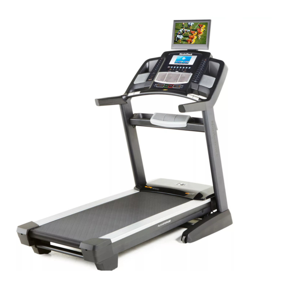
Thank you for selecting the revolutionary reading this manual, please see the front cover of this NORDICTRACK ELITE 4000 treadmill. The ELITE manual. To help us assist you, please note the product ® 4000 treadmill offers an impressive selection of fea- model number and serial number before contacting us. -
Page 7: Part Identification Chart
PART IDENTIFICATION CHART Use the drawings below to identify small parts used for assembly. The number in parentheses below each draw- ing is the key number of the part, from the PART LIST near the end of this manual. The number following the key number is the quantity used for assembly. - Page 8 ASSEMBLY • Assembly requires two persons. • To identify small parts, see page 7. • Place all parts in a cleared area and remove the • Assembly requires the following tools: packing materials. Do not dispose of the packing materials until you finish all assembly steps. the included hex key •...
- Page 9 3. Identify the Left and Right Upright Covers (89, 90). Slide the Left Upright Cover (89) onto the left Upright (84), and slide the Right Upright Cover (90) onto the right Upright. Do not press the Upright Covers into place yet. Then, remove and save the four indicated 5/16"...
- Page 10 6. Hold the Tray (79) near the right Upright (84). Wrap the tie in the hole in the side of the Upright around the end of the fan wire (B). Pull the fan wire into the hole and out of the top of the Upright.
- Page 11 8. Set the console assembly (D) face down on a soft surface to avoid scratching the console assembly. Remove and discard the four indicated screws (E). Then, remove the Pulse Crossbar (80). 9. IMPORTANT: To avoid damaging the Pulse Crossbar (80), do not use power tools, and do not overtighten the #10 x 3/4"...
- Page 12 10. With the help of a second person, hold the con- sole assembly (D) near the Handrails (74). See the inset drawing. Connect the Upright Wire (83) to the console wire (F). The connec- tors should slide together easily and snap into place.
- Page 13 12. Identify the #8 x 3/4" Screws (5). IMPORTANT: Do not confuse the #8 x 3/4" Screws with the #8 x 3/4" Truss Head Screws (24). The #8 x 3/4" Truss Head Screws have flatter heads. Start four #8 x 3/4" Screws (5) into the Pulse Crossbar (80), and then tighten them.
- Page 14 14. Raise the Frame (52) to the position shown. Have a second person hold the Frame until step 15 is completed. Orient the Storage Latch (56) so that the decal is facing away from the treadmill as shown. Attach the lower end of the Storage Latch (56) to the bracket on the base of the Upright (84) with a 5/16"...
- Page 15 16. Set the TV (133) face down on a soft surface to avoid scratching the TV. Remove and save the four M4 x 12mm Screws (130). 17. Insert the wires and the coaxial cable from the TV (133) through the hole in the TV Bracket (131) as shown.
- Page 16 19. Remove and discard the four indicated screws (K). Remove and save the four indicated 5/16" x 3/4" Assembly Screws (1). Hold the TV assembly near the console assem- bly. Connect the two wires and the coaxial cable on the TV assembly to the two wires and the coaxial cable on the console assembly.
- Page 17 21. Raise the Left Upright Cover (89), and connect the coaxial cable from your wall (or device) to the Upright Coaxial Cable (78). Then, press the Left Upright Cover (89) and the Right Upright Cover (not shown) onto the Uprights (84) until they snap into place. 22.
- Page 18 Before operating the TV, you must connect an antenna or a 75 ohm CATV cable to the 75 ohm terminal, an AV cable to the audio/video input jack, or an HDMI cable to the HDMI input jack. Note: Use a CATV cable to connect to an external source such as a cable box, satellite TV box, VCR, or analog cable.
- Page 19 HOW TO CONNECT A VCR, DVD PLAYER, OR HOW TO CONNECT A DVD OR BLU-RAY PLAYER OTHER DEVICE USING AN AV CABLE OR OTHER DEVICE USING AN HDMI CABLE 1. Connect the three-pronged end of an RCA AV 1. Connect one end of an HDMI cable to your DVD or cable to your VCR, DVD player, or other device.
-
Page 20: The Chest Heart Rate Monitor
THE CHEST HEART RATE MONITOR HOW TO PUT ON THE HEART RATE MONITOR • Do not expose the heart rate monitor to direct sun- light for extended periods of time; do not expose it to The heart rate temperatures above 122° F (50° C) or below 14° F monitor consists of (-10°... -
Page 21: How To Use The Treadmill
HOW TO USE THE TREADMILL HOW TO PLUG IN THE POWER CORD Follow the steps below to plug in the power cord. This product must be earthed. If it should malfunc- 1. Plug the indicated end of the power cord into the tion or break down, earthing provides a path of least socket on the treadmill. - Page 22 CONSOLE DIAGRAM MAKE YOUR FITNESS GOALS A REALITY WITH FEATURES OF THE CONSOLE IFIT.COM The advanced treadmill console offers an array of fea- With your new iFit-compatible fitness equipment, you tures designed to make your workouts more effective can use an array of features on iFit.com to make your and enjoyable.
- Page 23 HOW TO TURN ON THE POWER HOW TO USE THE TOUCH SCREEN IMPORTANT: If the treadmill has been exposed to The console features a tablet with a full-color touch cold temperatures, allow it to warm to room tem- screen. The following information will help you become perature before you turn on the power.
- Page 24 HOW TO SET UP THE CONSOLE To use the equipment settings mode, see page 30. To use the sound system, see page 31. To Before using the treadmill for the first time, set up the use the Internet browser, see page 32. To use the maintenance mode, see page 32.
- Page 25 3. Start the walking belt and adjust the speed. As you walk or run on the treadmill, the screen can show the following workout information: Touch the Start button on the screen or press the Start button on the console to start the walking •...
- Page 26 To measure your heart rate, stand on the foot HOW TO USE AN ONBOARD WORKOUT rails and hold the contacts with your palms for approximately ten seconds; avoid moving your 1. Insert the key into the console. hands. When your pulse is detected, your heart rate will be shown.
- Page 27 5. Measure your heart rate if desired. At the end of the first segment of the workout, the treadmill will automatically adjust to the speed and/ or incline settings for the next segment. See step 6 on page 25. 6. Turn on the fan if desired. The workout will continue in this way until the last segment ends.
- Page 28 4. Start the workout. HOW TO USE A PULSE WORKOUT Touch the Start button to start the workout. A Pulse workouts automatically control the speed and moment after you touch the button, the walking belt incline of the treadmill to keep your heart rate near a will begin to move.
- Page 29 6. Monitor your progress with the displays. workout of that type in your schedule. Note: You may be able to access demo workouts through See step 5 on page 25. these options, even if you do not log in to an iFit account.
- Page 30 7. Measure your heart rate if desired. 4. Select the unit of measurement. See step 6 on page 25. Touch the US/Metric button to view the selected unit of measurement. Change the unit of measure- 8. Turn on the fan if desired. ment, if desired.
- Page 31 8. Enable or disable the Internet browser. 12. Set a safety screen timeout. To enable or disable the Internet browser, first The console features an automatic screen reset; if touch the Browser button. Next, touch the Enable no buttons are touched or pressed and the walking checkbox or the Disable checkbox.
- Page 32 HOW TO CHANGE THE AUDIO INPUT HOW TO USE THE MAINTENANCE MODE To select a different audio source, touch the music 1. Select the settings main menu. notes button at the bottom of the screen. Then, choose an audio source from the list. Note: Select Personal TV See step 1 on page 30.
- Page 33 4. Calibrate the incline system of the treadmill. HOW TO USE THE WIRELESS NETWORK MODE Touch the Calibrate Incline button. Then, touch the The console features a wireless network mode that Begin button to calibrate the incline system. The allows you to set up a wireless network connection. treadmill will automatically rise to the maximum incline level, lower to the minimum incline level, 1.
- Page 34 HOW TO OPERATE THE DIGITAL TV An information box will ask if you want to connect to the wireless network. Touch the Connect button to connect to the network or touch the Cancel but- You can control the digital TV with the buttons on the ton to return to the list of networks.
- Page 35 4. Adjust the volume as desired. 3. Set default settings. Press the Vol increase and decrease buttons to Touch the Default Settings button and set a default adjust the volume level. When the buttons are channel and a default volume level for the digital pressed, a graphic will appear on-screen to show TV if desired.
- Page 36 HOW TO REPLACE THE BATTERIES IN THE Press the return button ( ) to view the previous channel. REMOTE CONTROL Press the Menu button to view the main menu or to To replace the batteries, view a previous menu. See this page for information first locate the battery about the menu.
- Page 37 2. Adjust the image settings. channels list. Select a name in the Label column to change the channel’s label. Edit the label using the The Picture menu offers numerous features for arrow buttons. adjusting the TV display. Use the arrow buttons to navigate through the various settings and personal- Select Channel List to view a list of channels saved ize the image settings.
- Page 38 6. Set up the basic television settings. HOW TO ADJUST THE CUSHIONING SYSTEM The Setup menu allows you to adjust the closed The treadmill features a cushioning system that caption settings, the language used in the menus, reduces the impact as you walk or run on the treadmill. or the clock settings.
-
Page 39: How To Fold And Move The Treadmill
HOW TO FOLD AND MOVE THE TREADMILL HOW TO FOLD THE TREADMILL HOW TO MOVE THE TREADMILL To avoid damaging the treadmill, adjust the incline Before moving the treadmill, fold it as described at the to zero before you fold the treadmill. Then, remove left. -
Page 40: Maintenance And Troubleshooting
MAINTENANCE AND TROUBLESHOOTING MAINTENANCE SYMPTOM: The power turns off during use Regularly clean the treadmill and keep the walking a. Check the power switch (see drawing c at the left). belt clean and dry. First, press the power switch into If the switch has tripped, wait for five minutes and the off position and unplug the power cord. - Page 41 Locate the Reed Switch (47) and the Magnet (45) b. If the walking belt is overtightened, treadmill per- on the left side of the Pulley (51). Turn the Pulley formance may decrease and the walking belt may until the Magnet is aligned with the Reed Switch. become damaged.
- Page 42 SYMPTOM: The walking belt is not centered SYMPTOM: The digital TV is not receiving a signal between the foot rails a. Make sure that the correct input source is selected. IMPORTANT: If the walking belt rubs against the See step 2 on page 34 to select an input source. foot rails, the walking belt may become damaged.
- Page 43 • Ghosts—Ghosts are caused by the TV signal fol- Note: If one of these problems appears when the lowing two paths—one is the direct path and the cable from a CATV company is connected, the other is reflected from tall buildings, hills, or other problem may be caused by the cable company objects.
-
Page 44: Exercise Guidelines
EXERCISE GUIDELINES Burning Fat—To burn fat effectively, you must exer- WARNING: cise at a low intensity level for a sustained period of Before beginning this time. During the first few minutes of exercise, your or any exercise program, consult your physi- body uses carbohydrate calories for energy. -
Page 45: Part List
PART LIST Model No. NETL30914.0 R0614A Key No. Qty. Description Key No. Qty. Description 5/16" x 3/4" Screw Drive Roller/Pulley 5/16" x 2" Screw Frame 5/16" x 1 3/4" Bolt 5/16" x 2 1/4" Bolt Drive Motor #8 x 3/4" Screw Motor Belt #10 x 3/4"... - Page 46 Key No. Qty. Description Key No. Qty. Description Right Tray Right Rear Cap Right Speaker Grill Foot Rail Plate Right Speaker Cover Foot Rail Bracket Key/Clip Cushion Wheel Stop Console Frame Cap Tray Fan Console Frame Tray Fan Cover Wire Tie Power Supply Pulse Strap Standoff...
-
Page 47: Exploded Drawing
EXPLODED DRAWING A Model No. NETL30914.0 R0614A... - Page 48 EXPLODED DRAWING B Model No. NETL30914.0 R0614A 33 112 33 117 115 111...
- Page 49 EXPLODED DRAWING C Model No. NETL30914.0 R0614A...
- Page 50 EXPLODED DRAWING D Model No. NETL30914.0 R0614A...
- Page 51 EXPLODED DRAWING E Model No. NETL30914.0 R0614A...
- Page 52 ORDERING REPLACEMENT PARTS To order replacement parts, please see the front cover of this manual. To help us assist you, be prepared to provide the following information when contacting us: • the model number and serial number of the product (see the front cover of this manual) •...
Need help?
Do you have a question about the Elite 4000 and is the answer not in the manual?
Questions and answers