Table of Contents
Advertisement
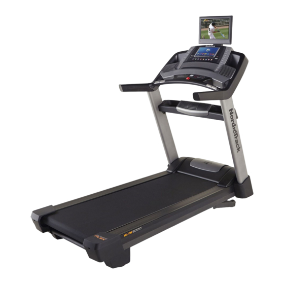
Model No. NETL40915.0
Serial No.
Write the serial number in the space
above for reference.
Serial Number Decal
CUSTOMER SERVICE
UNITED KINGDOM
Call: 0330 123 1045
From Ireland: 053 92 36102
Website: www.iconsupport.eu
E-mail: csuk@iconeurope.com
Write:
ICON Health & Fitness, Ltd.
Unit 1D, The Gateway
Fryers Way, Silkwood Park
OSSETT
WF5 9TJ
UNITED KINGDOM
AUSTRALIA
Call: 1800 993 770
E-mail: australiacc@iconfitness.com
Write:
ICON Health & Fitness
PO Box 635
WINSTON HILLS NSW 2153
AUSTRALIA
CAUTION
Read all precautions and instruc-
tions in this manual before using
this equipment. Save this manual
for future reference.
USER'S MANUAL
www.iconeurope.com
Advertisement
Table of Contents

Related Manuals for NordicTrack ELITE 5000


Summary of Contents for NordicTrack ELITE 5000
- Page 1 Model No. NETL40915.0 Serial No. USER’S MANUAL Write the serial number in the space above for reference. Serial Number Decal CUSTOMER SERVICE UNITED KINGDOM Call: 0330 123 1045 From Ireland: 053 92 36102 Website: www.iconsupport.eu E-mail: csuk@iconeurope.com Write: ICON Health & Fitness, Ltd. Unit 1D, The Gateway Fryers Way, Silkwood Park OSSETT...
-
Page 2: Table Of Contents
The BLUETOOTH ® word mark and logos are registered trademarks of Bluetooth SIG, Inc. and are used under license. Google Maps is a trademark of Google Inc. NORDICTRACK is a registered trademark of ICON Health & Fitness, Inc. -
Page 3: Important Precautions
IMPORTANT PRECAUTIONS WARNING: To reduce the risk of burns, fire, electric shock, or injury to persons, read all important precautions and instructions in this manual and all warnings on your treadmill before using your treadmill. ICON assumes no responsibility for personal injury or property damage sus- tained by or through the use of this product. - Page 4 21. Never leave the treadmill unattended while 30. To protect the treadmill and television dur- it is running. Always remove the key, press ing lightning storms, unplug the power cord the power switch into the off position (see from the wall outlet and disconnect the cable the drawing on page 6 for the location of the system.
- Page 5 36. Secure an antenna lead-in and ground wires 39. Note to CATV system installer: This reminder to the house with standoff insulators spaced is provided to call the CATV system install- from 4 to 6 feet (1.22 to 1.83 m) apart. er’s attention to Article 820-40 of the NEC or your local codes and ordinances that provide 37.
-
Page 6: Before You Begin
Thank you for selecting the revolutionary reading this manual, please see the front cover of this NORDICTRACK ELITE 5000 treadmill. The ELITE manual. To help us assist you, please note the product ® 5000 treadmill offers an impressive selection of fea- model number and serial number before contacting us. -
Page 7: Part Identification Chart
PART IDENTIFICATION CHART Use the drawings below to identify small parts used for assembly. The number in parentheses below each draw- ing is the key number of the part, from the PART LIST near the end of this manual. The number following the key number is the quantity used for assembly. -
Page 8: Assembly
ASSEMBLY • Assembly requires two persons. • To identify small parts, see page 7. • Place all parts in a cleared area and remove the • Assembly requires the following tools: packing materials. Do not dispose of the packing materials until you fi nish all assembly steps. the included hex key •... - Page 9 2. Make sure that the power cord is unplugged. Identify the Right Upright (116). Have a sec- ond person hold the Right Upright near the Frame (134). See the inset drawing. Tie the wire tie (A) in the Right Upright (116) securely around the end of the Upright Wire (117).
- Page 10 4. Remove and discard the four indicated screws (B). Then, remove the Tray Fan (104) from the Upright Crossbar (111). 5. Carefully slide the Upright Crossbar (111) between the Left and Right Uprights (115, 116). Attach the Upright Crossbar with four 5/16" x 3/4"...
- Page 11 7. Remove and save the four indicated 5/16" x 2" Screws (2). Attach the two Handrails (108) to the Left and Right Uprights (115, 116) with two of the 5/16" x 2" Screws (2) that you just removed and two 5/16"...
- Page 12 9. IMPORTANT: To avoid damaging the Pulse Crossbar (110), do not use power tools, and do not overtighten the #10 x 3/4" Screws (7) or the 5/16" x 2" Screws (2). Orient the Pulse Crossbar (110) as shown. Attach the Pulse Crossbar with two of the 5/16" x 2" Screws (2) that you removed in step 7, two 5/16"...
- Page 13 11. Attach the console assembly (G) to the Handrails (108) with four 5/16" x 2" Screws (2) and four 5/16" Star Washers (8); start all four Screws, and then tighten them. Be careful not to pinch the wires and cables. Insert the wires (K) and cables (L) upward into the console assembly (G).
- Page 14 13. Identify the #8 x 3/4" Truss Head Screws (6). IMPORTANT: Do not confuse the #8 x 3/4" Truss Head Screws with the #8 x 3/4" Screws (5). The #8 x 3/4" Truss Head Screws have flatter heads. Set the Left Handrail Top Cover (106) on the Left Handrail Bottom Cover (112).
- Page 15 15. Insert the wires and the coaxial cable (M) from the TV (138) through the hole (N) in the TV Bracket (135) as shown. See drawing 15b. Attach the TV Bracket (135) to the TV (138) with the four M4.2 x 12mm Screws (28) that you removed in step 14.
- Page 16 18. Attach the TV assembly (Q) to the console assembly (G) with the four 5/16" x 3/4" Screws (1) that you removed in step 17. Be careful not to pinch the wires; start all four Screws, and then tighten them. Then, attach the Lower TV Bracket Cover (140) with four #8 x 3/4"...
- Page 17 20. Tighten the two 3/8" x 3" Screws (3) and the 3/8" x 1" Screw (4) on each side of the treadmill. Press the Right Upright Cover (119) onto the Right Upright (116). Then, press the Right Inner Upright Cover (120) onto the top of the Right Upright Cover.
- Page 18 Before operating the TV, you must connect an antenna or a 75 ohm CATV cable to the 75 ohm terminal, an AV cable to the audio/video input jack, or an HDMI cable to the HDMI input jack. Note: Use a CATV cable to connect to an external source such as a cable box, satellite TV box, VCR, or analog cable.
- Page 19 HOW TO CONNECT A VCR, DVD PLAYER, OR HOW TO CONNECT A DVD OR BLU-RAY PLAYER OTHER DEVICE USING AN AV CABLE OR OTHER DEVICE USING AN HDMI CABLE 1. Connect the three-pronged end of an RCA AV 1. Connect one end of an HDMI cable to your DVD or cable to your VCR, DVD player, or other device.
-
Page 20: The Chest Heart Rate Monitor
THE CHEST HEART RATE MONITOR HOW TO PUT ON THE HEART RATE MONITOR • Store the heart rate monitor in a warm, dry place. Do not store the heart rate monitor in a plastic bag or If the heart rate monitor looks like the one shown other container that may trap moisture. -
Page 21: How To Use The Treadmill
HOW TO USE THE TREADMILL HOW TO PLUG IN THE POWER CORD Follow the steps below to plug in the power cord. This product must be earthed. If it should malfunc- 1. Plug the indicated end of the power cord into the tion or break down, earthing provides a path of least socket on the treadmill. - Page 22 CONSOLE DIAGRAM MAKE YOUR FITNESS GOALS A REALITY WITH FEATURES OF THE CONSOLE IFIT.COM The advanced treadmill console offers an array of fea- With your new iFit-enabled fitness equipment, you can tures designed to make your workouts more effective use an array of features on iFit.com to make your fit- and enjoyable.
- Page 23 HOW TO TURN ON THE POWER HOW TO USE THE TOUCH SCREEN IMPORTANT: If the treadmill has been exposed to The console features a tablet with a full-color touch cold temperatures, allow it to warm to room tem- screen. The following information will help you become perature before you turn on the power.
- Page 24 HOW TO SET UP THE CONSOLE The console is now ready for you to begin working out. The following pages explain the various workouts and Before using the treadmill for the first time, set up the other features that the console offers. console.
- Page 25 HOW TO USE THE MANUAL MODE Note: The first time you adjust the incline, you must first calibrate the incline system (see step 4 on 1. Insert the key into the console. page 34). See HOW TO TURN ON THE POWER on page 5.
- Page 26 6. Measure your heart rate if desired. 8. When you are finished exercising, remove the key from the console. You can measure your heart rate using either the handgrip heart rate monitor or an optional chest Step onto the walking platform and touch the home heart rate monitor Note: The console is compatible button or the back button on the screen or press with BLUETOOTH...
- Page 27 Battery Replacement—To replace the battery in the FCC Information—The speed ring complies with Part speed ring, follow the instructions below. Use only a 15 of the FCC Rules. Operation is subject to the fol- 3-volt, coin-shaped, lithium battery. lowing two conditions: (1) This device may not cause harmful interference, and (2) this device must accept 1.
- Page 28 HOW TO USE AN ONBOARD WORKOUT The workout will continue in this way until the last segment ends. The walking belt will then slow to 1. Insert the key into the console. a stop and a workout summary will appear on the screen.
- Page 29 5. Measure your heart rate if desired. 4. Start the workout. See step 6 on page 26. Touch the Start button to start the workout. A moment after you touch the button, the walking belt 6. Turn on the fan if desired. will begin to move.
- Page 30 HOW TO USE A PULSE WORKOUT 6. Monitor your progress with the displays. Pulse workouts automatically control the speed and See step 5 on page 25. incline of the treadmill to keep your heart rate near a target level while you exercise. Note: You must wear a 7.
- Page 31 4. Select an iFit workout. 6. Monitor your progress with the displays. To download See step 5 on page 25. The screen may also an iFit workout show a map of the trail you are walking or running. in your sched- ule, touch the During a competition workout, the screen will show Map, Train,...
- Page 32 2. Select the equipment settings mode. 7. Turn on or turn off the display demo mode. In the settings main menu, touch the Equipment The console features a display demo mode, Settings button. Note: Slide or fl ick the screen to designed to be used if the treadmill is displayed scroll up or down through the options if necessary.
- Page 33 11. Enable or disable a passcode. Next, press the play button on your personal audio player. The console features a child-safety passcode, Adjust the volume level using designed to prevent unauthorized users from using the volume increase and the treadmill. decrease buttons on the con- sole or the volume control on Touch the Passcode button.
- Page 34 HOW TO USE THE MAINTENANCE MODE Note: Occasionally, a firmware update may cause your console to function slightly differently. These 1. Select the settings main menu. updates are always designed to improve your exer- cise experience. See step 1 on page 31. 4.
- Page 35 HOW TO USE THE WIRELESS NETWORK MODE To use the keyboard, see HOW TO USE THE TOUCH SCREEN on page 23. The console features a wireless network mode that allows you to set up a wireless network connection. When the console is connected to your wireless network, the WiFi menu option at the top of the 1.
- Page 36 3. Select the desired channel. 7. When you are finished using the digital TV, turn off the digital TV. To select the desired cable channel, press the Chan increase and decrease buttons or the Key To turn off the digital TV, press the TV power button. Pad button.
- Page 37 HOW TO USE THE REMOTE CONTROL HOW TO REPLACE THE BATTERIES IN THE REMOTE CONTROL The first time you use the remote control, insert batteries (see HOW TO To replace the batteries, REPLACE THE BATTERIES IN THE first locate the battery REMOTE CONTROL at the right).
- Page 38 HOW TO ADJUST THE TV SETTINGS 4. Adjust the channel settings. The TV has a menu that allows you to adjust and per- The Channel menu allows you to save channels sonalize television settings. in the TV memory and select settings for chan- nels.
- Page 39 5. Adjust the parental control settings. Select the Blue Back to have the TV screen display blue when no signal is detected. The Parental menu allows you to block or allow various settings on the TV. Select No Signal Power Off to have the TV shut off if no signal is detected for 10 minutes.
-
Page 40: How To Move The Treadmill
HOW TO MOVE THE TREADMILL Before moving the treadmill, plug in the power cord and insert the key into the console (see HOW TO TURN ON THE POWER on page 23). Next, raise the incline to the highest position. Then, remove the key Handrail and unplug the power cord. -
Page 41: Maintenance And Troubleshooting
MAINTENANCE AND TROUBLESHOOTING MAINTENANCE SYMPTOM: The power turns off during use Regular maintenance is important for optimal perfor- a. Check the power switch (see drawing c at the left). mance and to reduce wear. Inspect and properly tighten If the switch has tripped, wait for fi ve minutes and all parts each time the treadmill is used. - Page 42 SYMPTOM: The walking belt slows when walked on d. If the walking belt still slows when walked on, see the front cover of this manual. a. If an extension cord is needed, use only a 3-conduc- tor, 14-gauge (1 mm ) cord that is no longer than 5 SYMPTOM: The walking belt is not centered ft.
- Page 43 SYMPTOM: The digital TV is not receiving a signal the signal is weak, the picture may be of poor quality or a blue screen may appear. If the signal a. Make sure that the correct input source is selected. is weak, it may be necessary to install an exter- See step 2 on page 35 to select an input source.
-
Page 44: Exercise Guidelines
EXERCISE GUIDELINES Burning Fat—To burn fat effectively, you must exer- WARNING: cise at a low intensity level for a sustained period of Before beginning this time. During the first few minutes of exercise, your or any exercise program, consult your physi- body uses carbohydrate calories for energy. -
Page 45: Part List
PART LIST Model No. NETL40915.0 R0915A Key No. Qty. Description Key No. Qty. Description 5/16" x 3/4" Screw Right Rear Cap 5/16" x 2" Screw Isolator 3/8" x 3" Screw Left Frame Cover 3/8" x 1" Screw Foot Rail Clip #8 x 3/4"... - Page 46 Key No. Qty. Description Key No. Qty. Description Incline Motor Fan Grill Incline Leg Fan Cover Incline Leg Spacer Tray Fan Console Console Frame Cap Left Handrail Top Cover Cable Tie Right Handrail Top Cover Left Tray Handrail Right Tray Ground Wire Console Base Pulse Crossbar...
-
Page 47: Exploded Drawing
EXPLODED DRAWING A Model No. NETL40915.0 R0915A... - Page 48 EXPLODED DRAWING B Model No. NETL40915.0 R0915A...
- Page 49 EXPLODED DRAWING C Model No. NETL40915.0 R0915A...
- Page 50 EXPLODED DRAWING D Model No. NETL40915.0 R0915A...
- Page 51 EXPLODED DRAWING E Model No. NETL40915.0 R0915A...
-
Page 52: Ordering Replacement Parts
ORDERING REPLACEMENT PARTS To order replacement parts, please see the front cover of this manual. To help us assist you, be prepared to provide the following information when contacting us: • the model number and serial number of the product (see the front cover of this manual) •...
Need help?
Do you have a question about the ELITE 5000 and is the answer not in the manual?
Questions and answers