Table of Contents
Advertisement
www.nordictrack.com
Model No. 831.24937.0
Serial No.
Write the serial number in the space
above for reference.
Serial Number
Decal
ACTIVATE YOUR
WARRANTY
To register your product and
activate your warranty today, go
to www.nordictrackservice.com/
registration.
CUSTOMER CARE
For service at any time, go to
www.nordictrackservice.com.
Or call 1-800-TO-BE-FIT
(1-800-862-3348)
Mon.–Fri. 6 a.m.–6 p.m. MT
Sat. 8 a.m.–12 p.m. MT
Please do not contact the store.
CAUTION
Read all precautions and instruc-
tions in this manual before using
this equipment. Save this manual
for future reference.
USER'S MANUAL
Advertisement
Table of Contents
Troubleshooting

Related Manuals for NordicTrack 831.24937.0


Summary of Contents for NordicTrack 831.24937.0
- Page 1 Model No. 831.24937.0 USER’S MANUAL Serial No. Write the serial number in the space above for reference. Serial Number Decal ACTIVATE YOUR WARRANTY To register your product and activate your warranty today, go to www.nordictrackservice.com/ registration. CUSTOMER CARE For service at any time, go to www.nordictrackservice.com.
-
Page 2: Table Of Contents
TABLE OF CONTENTS WARNING DECAL PLACEMENT ............. . . 2 IMPORTANT PRECAUTIONS . -
Page 3: Important Precautions
IMPORTANT PRECAUTIONS WARNING: To reduce the risk of burns, fire, electric shock, or injury to persons, read all important precautions and instructions in this manual and all warnings on your treadmill before using your treadmill. ICON assumes no responsibility for personal injury or property damage sus- tained by or through the use of this product. - Page 4 20. The heart rate monitor is not a medical 28. Over exercising may result in serious injury device. Various factors, including the user’s or death. If you feel faint or if you experience movement, may affect the accuracy of heart pain while exercising, stop immediately and rate readings.
- Page 5 34. Upon completion of any service or repairs to 38. Use a jumper wire not smaller than No. 6 the treadmill or the television, ask the ser- AWG (13.3 mm ) copper, or the equivalent, vice technician to perform safety checks to when a separate antenna-grounding elec- confirm that the unit is in proper operating trode is used.
-
Page 8: Before You Begin
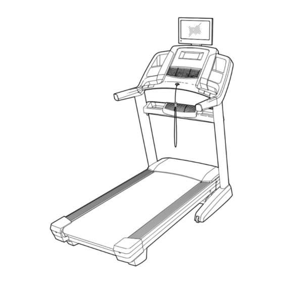
BEFORE YOU BEGIN Thank you for selecting the revolutionary reading this manual, please see the front cover of this NORDICTRACK ELITE 7700 treadmill. The ELITE manual. To help us assist you, please note the product ® 7700 treadmill offers an impressive selection of fea- model number and serial number before contacting us. -
Page 9: Part Identification Chart
PART IDENTIFICATION CHART Use the drawings below to identify small parts used for assembly. The number in parentheses below each draw- ing is the key number of the part, from the PART LIST near the end of this manual. The number following the key number is the quantity used for assembly. - Page 10 ASSEMBLY • Assembly requires two persons. • To identify small parts, see page 9. • Place all parts in a cleared area and remove the • Assembly requires the following tools: packing materials. Do not dispose of the packing materials until you fi nish all assembly steps. the included hex key •...
- Page 11 3. Identify the Left and Right Upright Covers (89, 90). Slide the Left Upright Cover (89) onto the left Upright (84), and slide the Right Upright Cover (90) onto the right Upright. Do not press the Upright Covers into place yet. Then, remove and save the four indicated 5/16"...
- Page 12 6. Hold the Tray (79) near the right Upright (84). Wrap the tie in the hole in the side of the Upright around the end of the fan wire (B). Pull the fan wire through the hole and out of the top of the Upright.
- Page 13 9. IMPORTANT: To avoid damaging the Pulse Crossbar (80), do not use power tools, and do not overtighten the #10 x 3/4" Screws (6) or the 5/16" x 2" Screws (2). Orient the Pulse Crossbar (80) as shown. Attach the Pulse Crossbar with two of the 5/16" x 2" Screws (2) that you removed in step 3, two 5/16"...
- Page 14 11. Attach the console assembly (D) to the Handrails (74) with four 5/16" x 2" Screws (2) and four 5/16" Star Washers (8). Start all four Screws, and then tighten them. Be careful not to pinch the wires and cables. Insert the wires and cables upward into the con- sole assembly (D).
- Page 15 13. Set the Left Handrail Top Cover (73) on the left Handrail (74). Start four #8 x 3/4" Truss Head Screws (24) into the Left Handrail Bottom Cover (75), the left Handrail, and the Left Handrail Top Cover. Slide the Left Handrail Top and Bottom Covers forward against the console assembly (D) as shown.
- Page 16 15. Align the upper end of the Storage Latch (56) with the bracket on the Frame (52). Insert a 5/16" x 2 1/4" Bolt (4) through the bracket. This should push a spacer (I) out of the other end. Discard the spacer. Attach the Storage Latch (56) with the 5/16"...
- Page 17 17. Insert the wires and the coaxial cable from the TV (133) through the hole in the TV Bracket (131) as shown. See 17b. Attach the TV Bracket (131) to the TV (133) with the four M4 x 12mm Screws (130) that you removed in step 16.
- Page 18 20. Attach the TV assembly to the console assembly with the four 5/16" x 3/4" Screws (1) that you removed in step 19. Be careful not to pinch the wires. Start all four Screws, and then tighten Assembly them. Console Attach the Lower TV Bracket Cover (135) with Assembly four #8 x 3/4"...
- Page 19 Before operating the TV, you must connect an antenna or a 75 ohm CATV cable to the 75 ohm terminal, an AV cable to the audio/video input jack, or an HDMI cable to the HDMI input jack. Note: Use a CATV cable to connect to an external source such as a cable box, satellite TV box, VCR, or analog cable.
- Page 20 HOW TO CONNECT A VCR, DVD PLAYER, OR HOW TO CONNECT A DVD OR BLU-RAY PLAYER OTHER DEVICE USING AN AV CABLE OR OTHER DEVICE USING AN HDMI CABLE 1. Connect the three-pronged end of an RCA AV 1. Connect one end of an HDMI cable to your DVD or cable to your VCR, DVD player, or other device.
-
Page 21: The Chest Heart Rate Monitor
THE CHEST HEART RATE MONITOR HOW TO PUT ON THE HEART RATE MONITOR • Do not expose the heart rate monitor to direct sun- light for extended periods of time; do not expose it to The heart rate temperatures above 122° F (50° C) or below 14° F monitor consists of (-10°... -
Page 22: Operation And Adjustment
OPERATION AND ADJUSTMENT HOW TO CONNECT THE POWER CORD nominal 120-volt circuit capable of carrying 15 or more amps. To avoid overloading the circuit, do Use a Surge Suppressor not plug other electrical devices, except for low- power devices such as cell phone chargers, into Your treadmill, like other electronic equipment, can be the surge suppressor or into an outlet on the same damaged by sudden voltage changes in your home’s... - Page 23 CONSOLE DIAGRAM MAKE YOUR FITNESS GOALS A REALITY WITH FEATURES OF THE CONSOLE IFIT.COM The advanced treadmill console offers an array of fea- With your new iFit-compatible fitness equipment, you tures designed to make your workouts more effective can use an array of features on iFit.com to make your and enjoyable.
- Page 24 HOW TO TURN ON THE POWER HOW TO USE THE TOUCH SCREEN IMPORTANT: If the treadmill has been exposed to The console features a tablet with a full-color touch cold temperatures, allow it to warm to room tem- screen. The following information will help you become perature before you turn on the power.
- Page 25 HOW TO SET UP THE CONSOLE The console is now ready for you to begin working out. The following pages explain the various workouts and Before using the treadmill for the first time, set up the other features that the console offers. console.
- Page 26 HOW TO USE THE MANUAL MODE numbered Incline/Decline buttons. Each time you press one of the buttons, the incline will gradually 1. Insert the key into the console. change until it reaches the selected incline setting. See HOW TO TURN ON THE POWER on page Note: The first time you adjust the incline, you must 24.
- Page 27 6. Measure your heart rate if desired. 7. Turn on the fan if desired. Note: If you use the handgrip heart rate moni- The fan features several speed settings and an tor and the chest heart rate monitor at the same auto mode.
- Page 28 HOW TO USE AN ONBOARD WORKOUT If the speed and/or incline settings are too high or too low at any time during the workout, you can 1. Insert the key into the console. override the settings by pressing the Speed or Incline buttons.
- Page 29 HOW TO USE A SET-A-GOAL WORKOUT The workout will function in the same way as the manual mode (see pages 26). 1. Insert the key into the console. The workout will continue until you reach the goal See HOW TO TURN ON THE POWER on that you set.
- Page 30 HOW TO USE A PULSE WORKOUT 5. Start the workout. Pulse workouts automatically control the speed and Touch the Start Workout button on the screen to incline of the treadmill to keep your heart rate near a start the workout. A moment after you touch the target level while you exercise.
- Page 31 HOW TO USE AN IFIT WORKOUT Before some workouts will download, you must add them to your schedule on iFit.com. Note: To use an iFit workout, you must have access to a wireless network (see HOW TO USE THE For more information about the iFit workouts, WIRELESS NETWORK MODE on page 35).
- Page 32 HOW TO USE THE EQUIPMENT SETTINGS MODE IMPORTANT: You must still unplug the power cord after using the treadmill. Set the update 1. Select the settings main menu. time for a time when you normally use the treadmill and will be available to unplug the Insert the key into the console power cord after an update.
- Page 33 11. Enable or disable a passcode. Next, press the play button on your per- sonal audio player. Adjust the volume level The console features a child-safety passcode, using the volume increase and decrease designed to prevent unauthorized users from using buttons on the console or the volume con- the treadmill.
- Page 34 HOW TO USE THE MAINTENANCE MODE Note: Occasionally, a firmware update may cause your console to function slightly differently. These 1. Select the settings main menu. updates are always designed to improve your exer- cise experience. See step 1 on page 32. 4.
- Page 35 HOW TO USE THE WIRELESS NETWORK MODE An information box will ask if you want to connect to the wireless network. Touch the Connect button The console features a wireless network mode that to connect to the network or touch the Cancel but- allows you to set up a wireless network connection.
- Page 36 HOW TO OPERATE THE DIGITAL TV 5. Mute the digital TV if desired. You can control the digital TV with the buttons on the Press the Mute button to mute the digital TV’s audio console, with the buttons on the top of the digital TV, or output.
- Page 37 HOW TO USE THE REMOTE CONTROL Press the Display button to view information about the current program and the broadcast or cable signal. The first time you use the remote control, insert batteries (see HOW TO Press the CC button repeatedly to turn on or turn off REPLACE THE BATTERIES IN THE closed captioning.
- Page 38 HOW TO ADJUST THE TV SETTINGS 4. Adjust the channel settings. The TV has a menu that allows you to adjust and per- The Channel menu allows you to save channels sonalize television settings. in the TV memory and select settings for chan- nels.
- Page 39 5. Adjust the parental control settings. Select the Blue Back to have the TV screen display blue when no signal is detected. The Parental menu allows you to block or allow various settings on the TV. Select No Signal Power Off to have the TV shut off if no signal is detected for 10 minutes.
-
Page 40: How To Fold And Move The Treadmill
HOW TO FOLD AND MOVE THE TREADMILL HOW TO FOLD THE TREADMILL HOW TO MOVE THE TREADMILL To avoid damaging the treadmill, adjust the incline Before moving the treadmill, fold it as described at the to zero before you fold the treadmill. Then, remove left. -
Page 41: Troubleshooting
TROUBLESHOOTING Most treadmill problems can be solved by following c. Remove the key from the console, and then the simple steps below. Find the symptom that reinsert it. applies, and follow the steps listed. If further assis- tance is needed, see the front cover of this manual. d. - Page 42 Locate the Reed Switch (47) and the Magnet (45) careful to keep the walking belt centered. Then, on the left side of the Pulley (51). Turn the Pulley plug in the power cord, insert the key, and run the until the Magnet is aligned with the Reed Switch. treadmill for a few minutes.
- Page 43 b. If the walking belt slips when walked on, fi rst • Ignition (black spots or horizontal streaks that remove the key and UNPLUG THE POWER appear or a picture that fl utters or drifts)— CORD. Using the hex key, turn both idler roller Usually this is caused by interference from screws clockwise, 1/4 of a turn.
-
Page 44: Exercise Guidelines
EXERCISE GUIDELINES Burning Fat—To burn fat effectively, you must exer- WARNING: cise at a low intensity level for a sustained period of Before beginning this time. During the first few minutes of exercise, your or any exercise program, consult your physi- body uses carbohydrate calories for energy. -
Page 45: Part List
PART LIST Model No. 831.24937.0 R0114A Key No. Qty. Description Key No. Qty. Description 5/16" x 3/4" Screw Drive Roller/Pulley 5/16" x 2" Screw Frame 5/16" x 1 3/4" Bolt 5/16" x 2 1/4" Bolt Drive Motor #8 x 3/4" Screw Motor Belt #10 x 3/4"... - Page 46 Key No. Qty. Description Key No. Qty. Description Right Tray Cushion Spring Right Speaker Grill Left Rear Cap Right Speaker Cover Right Rear Cap Key/Clip Foot Rail Plate Console Frame Cap Right Rear Cap Console Frame Cushion Wheel Stop Wire Tie Tray Fan Pulse Strap Tray Fan Cover...
-
Page 47: Exploded Drawing
EXPLODED DRAWING A Model No. 831.24937.0 R0114A... - Page 48 EXPLODED DRAWING B Model No. 831.24937.0 R0114A 33 112 33 117 115 111...
- Page 49 EXPLODED DRAWING C Model No. 831.24937.0 R0114A...
- Page 50 EXPLODED DRAWING D Model No. 831.24937.0 R0114A...
- Page 51 EXPLODED DRAWING E Model No. 831.24937.0 R0114A...
-
Page 52: Ordering Replacement Parts
ORDERING REPLACEMENT PARTS To order replacement parts, please see the front cover of this manual. To help us assist you, be prepared to provide the following information when contacting us: • the model number and serial number of the product (see the front cover of this manual) •...
Need help?
Do you have a question about the 831.24937.0 and is the answer not in the manual?
Questions and answers
Where is the factor reset on the treadmill elite runner 7700 and how to complete a factory reset. My treadmill is stuck on first screen