Table of Contents
Advertisement
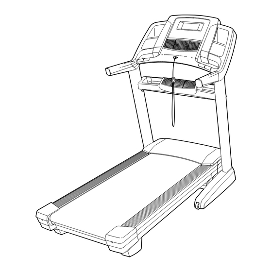
Model No. NETL24714.0
Serial No.
USER'S MANUAL
Write the serial number in the space
above for reference.
Serial Number
Decal
CUSTOMER SERVICE
UNITED KINGDOM
Call: 0330 123 1045
From Ireland: 053 92 36102
Website: www.iconsupport.eu
E-mail: csuk@iconeurope.com
Write:
ICON Health & Fitness, Ltd.
Unit 1D, The Gateway
Fryers Way, Silkwood Park
OSSETT
WF5 9TJ
UNITED KINGDOM
AUSTRALIA
Call: 1800 993 770
E-mail: australiacc@iconfitness.com
Write:
ICON Health & Fitness
PO Box 635
WINSTON HILLS NSW 2153
AUSTRALIA
CAUTION
Read all precautions and instruc-
tions in this manual before using
this equipment. Save this manual
www.iconeurope.com
for future reference.
Advertisement
Table of Contents

Related Manuals for NordicTrack Elite 2500


Summary of Contents for NordicTrack Elite 2500
- Page 1 Model No. NETL24714.0 Serial No. USER’S MANUAL Write the serial number in the space above for reference. Serial Number Decal CUSTOMER SERVICE UNITED KINGDOM Call: 0330 123 1045 From Ireland: 053 92 36102 Website: www.iconsupport.eu E-mail: csuk@iconeurope.com Write: ICON Health & Fitness, Ltd. Unit 1D, The Gateway Fryers Way, Silkwood Park OSSETT...
-
Page 2: Table Of Contents
Apply the decal in the location shown. Note: The decals may not be shown at actual size. 305284 NORDICTRACK is a registered trademark of ICON Health & Fitness, Inc. -
Page 3: Important Precautions
IMPORTANT PRECAUTIONS WARNING: To reduce the risk of burns, fire, electric shock, or injury to persons, read all important precautions and instructions in this manual and all warnings on your treadmill before using your treadmill. ICON assumes no responsibility for personal injury or property damage sus- tained by or through the use of this product. - Page 4 19. Never leave the treadmill unattended while 23. Never insert any object into any opening on it is running. Always remove the key, press the treadmill. the power switch into the off position (see the drawing on page 5 for the location of the 24.
-
Page 5: Before You Begin
Thank you for selecting the revolutionary reading this manual, please see the front cover of this NORDICTRACK ELITE 2500 treadmill. The ELITE manual. To help us assist you, please note the product ® 2500 treadmill offers an impressive selection of fea- model number and serial number before contacting us. -
Page 6: Part Identification Chart
PART IDENTIFICATION CHART Use the drawings below to identify small parts used for assembly. The number in parentheses below each draw- ing is the key number of the part, from the PART LIST near the end of this manual. The number following the key number is the quantity used for assembly. -
Page 7: Assembly
ASSEMBLY • Assembly requires two persons. • To identify small parts, see page 6. • Place all parts in a cleared area and remove the • Assembly requires the following tools: packing materials. Do not dispose of the packing materials until you finish all assembly steps. the included hex key •... -
Page 8: Identify The Right Extension Leg (91). Attach The
2. Make sure that the power cord is unplugged. Identify the Right Extension Leg (91). Attach the Right Extension Leg to the right Upright (84) with two 5/16" x 3/4" Screws (1). Start both Screws, and then tighten them. Attach the Left Extension Leg (not shown) to the left Upright (84) in the same way. - Page 9 4. Remove and discard the four indicated screws (A). Remove the Tray (79) from the Upright Crossbar (76). 5. Carefully slide the Upright Crossbar (76) between the Uprights (84). Attach the Upright Crossbar with four 5/16" x 3/4" Screws (1). Start all four Screws, and then tighten them.
- Page 10 7. Attach the two Handrails (74) to the Uprights (84) with two of the 5/16" x 2" Screws (2) that you removed in step 3 and two 5/16" Star Washers (8). Do not fully tighten the Screws yet. Be careful not to pinch the Upright Wire (83) or the fan wire (B) on the right side.
- Page 11 9. IMPORTANT: To avoid damaging the Pulse Crossbar (80), do not use power tools, and do not overtighten the #10 x 3/4" Screws (6) or the 5/16" x 2" Screws (2). Orient the Pulse Crossbar (80) as shown. Attach the Pulse Crossbar with two of the 5/16" x 2" Screws (2) that you removed in step 3, two 5/16"...
- Page 12 11. Attach the console assembly (D) to the Handrails (74) with four 5/16" x 2" Screws (2) and four 5/16" Star Washers (8). Start all four Screws, and then tighten them. Be careful not to pinch the wires. Insert the wires upward into the console assem- bly (D).
- Page 13 13. Set the Left Handrail Top Cover (73) on the left Handrail (74). Start four #8 x 3/4" Truss Head Screws (24) into the Left Handrail Bottom Cover (75), the left Handrail, and the Left Handrail Top Cover. Next, slide the Left Handrail Top and Bottom Covers forward against the console assembly (B) as shown.
- Page 14 15. Align the upper end of the Storage Latch (56) with the bracket on the Frame (52). Insert a 5/16" x 2 1/4" Bolt (4) through the bracket. This should push a spacer (I) out of the other end. Discard the spacer. Attach the Storage Latch (56) with the 5/16"...
-
Page 15: The Chest Heart Rate Monitor
THE CHEST HEART RATE MONITOR HOW TO PUT ON THE HEART RATE MONITOR • Do not expose the heart rate monitor to direct sun- light for extended periods of time; do not expose it to The heart rate temperatures above 122° F (50° C) or below 14° F monitor consists of (-10°... -
Page 16: How To Use The Treadmill
HOW TO USE THE TREADMILL HOW TO PLUG IN THE POWER CORD Follow the steps below to plug in the power cord. This product must be earthed. If it should malfunc- 1. Plug the indicated end of the power cord into the tion or break down, earthing provides a path of least socket on the treadmill. - Page 17 CONSOLE DIAGRAM MAKE YOUR FITNESS GOALS A REALITY WITH FEATURES OF THE CONSOLE IFIT.COM The advanced treadmill console offers an array of fea- With your new iFit-compatible fitness equipment, you tures designed to make your workouts more effective can use an array of features on iFit.com to make your and enjoyable.
- Page 18 HOW TO TURN ON THE POWER IMPORTANT: Before you use the treadmill, take the following steps to ensure that the the console IMPORTANT: If the treadmill has been exposed to shows the correct incline level of the treadmill: cold temperatures, allow it to warm to room tem- First, press the Incline increase button once.
- Page 19 HOW TO SET UP THE CONSOLE use the Internet browser, see page 26. To use the maintenance mode, see page 27. To use the wire- Before using the treadmill for the first time, set up the less network mode, see page 27. console.
- Page 20 If you press one of the numbered Speed buttons, • The distance that you have walked or run the walking belt will gradually change speed until it reaches the selected speed setting. • The number of vertical meters you have climbed To stop the walking belt, press the Stop button.
- Page 21 7. Turn on the fan if desired. Then, select the desired workout. The screen will show the name, duration, and distance of the work- The fan features several speed settings and an out. The screen will also show the approximate auto mode.
- Page 22 3. Select a set-a-goal workout. To pause the workout, touch either the back button or the home button in the lower left corner of the screen, or press the Stop button on the console. To To select a continue the workout, touch the Resume button or set-a-goal press the Start button on the console.
- Page 23 5. Monitor your progress with the displays. 4. Enter your maximum heart rate. See step 5 on page 20. Touch the increase and decrease buttons to enter your maximum heart rate. You can also adjust the 6. Measure your heart rate if desired. maximum speed and duration for the workout.
- Page 24 3. Log in to your iFit account. 5. Start the workout. If you have not already done so, touch the Login See step 3 on page 21. button to log in to your iFit account. The screen will ask for your iFit.com username and password. During some workouts, an audio coach may guide Enter them and touch the Submit button.
- Page 25 2. Select the equipment settings mode. 7. Turn on or turn off the display demo mode. In the settings main menu, touch the Equipment The console features a display demo mode, Settings button. Note: Slide or flick the screen to designed to be used if the treadmill is displayed scroll up or down through the options if necessary.
- Page 26 11. Enable or disable a passcode. Next, press the play button on your personal audio player. Adjust the volume The console features a child-safety passcode, level using the volume increase and designed to prevent unauthorized users from using decrease buttons on the console or the the treadmill.
- Page 27 HOW TO USE THE MAINTENANCE MODE 4. Calibrate the incline system of the treadmill. 1. Select the settings main menu. Touch the Calibrate Incline button. Then, touch the Begin button to calibrate the incline system. The See step 1 on page 24. treadmill will automatically rise to the maximum incline level, lower to the minimum incline level, 2.
-
Page 28: Wireless Network Mode
3. Enable Wi-Fi. If you are having problems connecting to an encrypted network, make sure that your password Make sure that the Wi-Fi checkbox is marked with is correct. Note: Passwords are case-sensitive. a green checkmark. If it is not, touch the Wi-Fi menu option once and wait for a few seconds. -
Page 29: How To Fold And Move The Treadmill
HOW TO FOLD AND MOVE THE TREADMILL HOW TO FOLD THE TREADMILL HOW TO MOVE THE TREADMILL To avoid damaging the treadmill, adjust the incline Before moving the treadmill, fold it as described at the to zero before you fold the treadmill. Then, remove left. -
Page 30: Maintenance And Troubleshooting
MAINTENANCE AND TROUBLESHOOTING MAINTENANCE SYMPTOM: The power turns off during use Regularly clean the treadmill and keep the walking a. Check the power switch (see drawing c at the left). belt clean and dry. First, press the power switch into If the switch has tripped, wait for five minutes and the off position and unplug the power cord. - Page 31 Locate the Reed Switch (47) and the Magnet (45) b. If the walking belt is overtightened, treadmill per- on the left side of the Pulley (51). Turn the Pulley formance may decrease and the walking belt may until the Magnet is aligned with the Reed Switch. become damaged.
- Page 32 SYMPTOM: The walking belt is not centered SYMPTOM: The walking belt slips when walked on between the foot rails a. First, remove the key and UNPLUG THE POWER IMPORTANT: If the walking belt rubs against the CORD. Using the hex key, turn both idler roller foot rails, the walking belt may become damaged.
-
Page 33: Exercise Guidelines
EXERCISE GUIDELINES Burning Fat—To burn fat effectively, you must exer- WARNING: cise at a low intensity level for a sustained period of Before beginning this time. During the first few minutes of exercise, your or any exercise program, consult your physi- body uses carbohydrate calories for energy. -
Page 34: Part List
PART LIST Model No. NETL24714.0 R0514A Key No. Qty. Description Key No. Qty. Description 5/16" x 3/4" Screw Drive Roller/Pulley 5/16" x 2" Screw Frame 5/16" x 1 3/4" Bolt 5/16" x 2 1/4" Bolt Drive Motor #8 x 3/4" Screw Motor Belt #10 x 3/4"... - Page 35 Key No. Qty. Description Key No. Qty. Description Right Tray Cushion Rod Right Speaker Grill Cushion Wheel Right Speaker Cover Cushion Plate Key/Clip Cushion Spring Console Frame Cap Left Rear Cap Console Frame Right Rear Cap Wire Tie Foot Rail Plate Pulse Strap Right Rear Cap Pulse Sensor...
-
Page 36: Exploded Drawing
EXPLODED DRAWING A Model No. NETL24714.0 R0514A... - Page 37 EXPLODED DRAWING B Model No. NETL24714.0 R0514A 33 112 33 117 115 111...
- Page 38 EXPLODED DRAWING C Model No. NETL24714.0 R0514A...
- Page 39 EXPLODED DRAWING D Model No. NETL24714.0 R0514A...
-
Page 40: Ordering Replacement Parts
ORDERING REPLACEMENT PARTS To order replacement parts, please see the front cover of this manual. To help us assist you, be prepared to provide the following information when contacting us: • the model number and serial number of the product (see the front cover of this manual) •...
Need help?
Do you have a question about the Elite 2500 and is the answer not in the manual?
Questions and answers