Table of Contents
Advertisement
Advertisement
Table of Contents

Related Manuals for URC MRX-20


Summary of Contents for URC MRX-20
- Page 1 Owner’s Manual MRX-20 Advanced Network System Controller...
- Page 2 The information in this Owner’s Manual is copyright protected. No part of this manual may be copied or reproduced in any form without prior written consent from Universal Remote Control, Inc. UNIVERSAL REMOTE CONTROL, INC. SHALL NOT BE LIABLE FOR OPERATIONAL, TECHNICAL OR EDITORIAL ERRORS/OMISSIONS MADE IN THIS MANUAL. The information in this Owner’s Manual may be subject to change without prior notice.
- Page 3 Programmable Only by URC Professional Installers To fully automate your audio/video system, the installer must have detailed knowledge of each component, LAN configuration, Wi-Fi optimization, the URC product, its accompanying software and how the system is connected and operated. URC software is available ONLY to a trained and certified professional audio/video installer. Although technical assistance is available, it is offered to our certified professional installers who can install a URC controller in a timely and efficient manner.
-
Page 4: Table Of Contents
Chapter 1: MRX-20 Overview Congratulations! Features and Benefits Parts Guide Expanding your System Front Panel Descriptions Rear Panel Descriptions Chapter 2: Using Your System Navigating the On-screen Menu On-screen Menu Options Overview Using the On-screen Menus Add a Slideshow using Photo Viewer Adjusting the Settings Chapter 3: Settings and More... -
Page 5: Congratulations
Chapter 1: MRX-20 Overview Congratulations! Thank you for purchasing URC’s Total Control MRX-20 Advanced Network System Controller. The unit features an intuitive and interactive on-screen interface providing control of every connected device throughout the entire home. Now you can control your home theatre, lights, view the front door and so much more... -
Page 6: Expanding Your System
Expanding your System Expand the MRX-20’s capabilities throughout the entire home by using our URC user interfaces, in-wall controllers, z-wave devices and music players. Simply integrate any of just a few of the URC products listed below for extensive control. In-Wall Controllers Keypads provide you with convenient access to anything your URC system can control. -
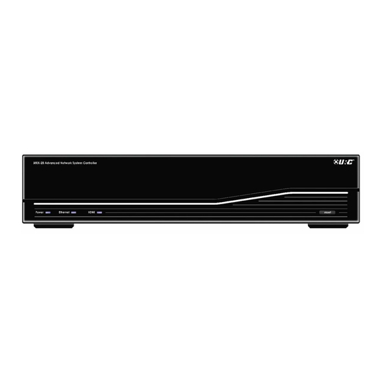
Page 7: Front Panel Descriptions
MRX-20 Front Panel Descriptions Power Ethernet HDMI Light Pipe Reset Button Front Panel Description Power Illuminates when unit is ON. LED indicates: • Connected: Illuminated Ethernet • Not connected: Blinks LED indicates: • Connected: Illuminated HDMI • Not connected: No illumination WARNING!! •... -
Page 8: Rear Panel Descriptions
MRX-20 Rear Panel Descriptions IR Outputs HDMI IN HDMI OUT Power Network Rear Panel Descriptions Power Connect power cable. Network Connect ethernet cable to communicate over the network. For future use! Ten 3.5mm IR emitter ports each (Each with output level attentuators.) - Page 9 MRX-20 Rear Panel Descriptions 12 Volt Trigger RFTX-1 RS-232 Relays Sensors Rear Panel Descriptions Two programmable 12V/0.2A outputs. Each may be programmed to turn ON, OFF or momentarily 12 Volt TOGGLE its output. Four programmable relays that maybe set to normally opened (NO), normally closed (NC) or Relays momentary contacts.
- Page 10 Chapter 2: Using Your System Navigating the MRX20’s On-screen Menu Navigating the MRX20’s on-screen menu is very simple with our URC User Interfaces such as the TRG-100/TRG-200 Umotion remotes, or URC’s wide assortment of handheld, in-wall, Android and iOS controllers. Using the TRG-100/200 Using other Total Control User Interfaces While using the TRG-100/TRG-200 remote, press the Umotion...
-
Page 11: On-Screen Menu Options Overview
On-screen Menu Options Overview Device Menu Main Menu Use the Device The Main Menu Menu to access allows control of all of a device’s any “connected commands. Click device” in the the title to learn Total Control more. System. Click the title to learn more. -
Page 12: Using The On-Screen Menus
Using the On-screen Menus Main Menu The Main Menu accesses any “connected device” in your Total Control System. Depending upon programming, most device /activities will be placed into subfolders (like Music, Entertainment, etc.). Accessing these subfolders will allow you to control any device that is available in the chosen room (see Rooms Menu). - Page 13 The current room portion of the Title Bar shows the room that the MRX-20 is controlling. Remember, in a Total Control system, the MRX-20 will default to control the room in which it is placed. Use the Rooms Menu to control any other room in the system.
- Page 14 Categories/Devices Ribbon This ribbon shows the various categories of control that are available to the selected room. The quantity of categories is determined by the system setup and can vary from one to multiple categories programmed by the system designer. Although only seven categories can fit on the screen at any moment, navigate left or right to other categories, if available.
- Page 15 Status Bar The Status Bar, located at the bottom of the screen, provides valuable status and feedback of the Total Control system. The four sections of the Status Bar are determined by the system programmer. Status Bar Descriptions Sunrise Time Updated at midnight every day, this shows the sunrise time for the next day.
- Page 16 Rooms Menu The Rooms Menu offers the user control of every room throughout the home. It is now easier to turn off lights throughout the home while in the Master Bedroom. The Rooms Menu is used to: • Temporarily Link rooms in a Total Control DMS Links system.
- Page 17 Selecting any room from the room list will allow the MRX-20 to control that room, as if it were physically in that location. Returning the MRX-20 to control the room where it is physically located requires accessing the Rooms Menu and selecting the appropriate room.
- Page 18 Using Linked Rooms Once a room is linked, pressing the volume or mute buttons for that room will cause the Linked Rooms Volume Pop-Up to display. This menu will display the volume levels for all rooms in the temporary group. •...
- Page 19 Device Menu When the basic commands found in the Quick Bar do not include the action you need to perform, use the Device Menu to access all of that device’s commands. For example, your custom programmer may not have included an EJECT command in the DVD’s Quick Bar menu.
- Page 20 Device Menu Descriptions Exit Closes the Device menu. Customizable These buttons vary based on the type of device (Cable, DVD, etc...) A maximum of ten buttons can be Buttons modified by your URC Professional Installer. Shortcuts Opens the Shortcuts menu with a list of user selected favorite devices. This option is only available when using a device with stored favorites.
- Page 21 Quick Bar Menu While watching or listening to a device, such as a Cable or CD, access the Quick Bar menu with a TRG-100/200 remote by pressing the Umotion button. The Quick Bar menu opens. Move the remote around the on-screen interface to reveal the on-screen cursor. Hover over a button and press the Umotion button again to select.
- Page 22 Quick Bar Menu Descriptions Exit Closes the Quick Bar menu. Customizable These buttons vary based on the type of device (Cable, DVD, etc...) A maximum of ten buttons can be Buttons modified by your URC Professional Installer. Shortcuts Opens the Shortcuts menu with a list of user selected favorite devices. This option is only available when using a device with stored favorites.
- Page 23 Shortcuts Menu There are a maximum of six (6) shortcuts per room location. Remember, the MRX-20 can access any room in the Total Control system regardless of its physical location. Only items that appear in the currently selected room are available to be added to the Shortcuts menu.
- Page 24 This opens the Shortcuts Add/Edit screen, which allows the user to scroll through all of the devices/activities available to that room. Select up to 6 devices/activities by selecting the check box shown for each possibility. Once all 6 are chosen, the remaining devices/activities will be grayed out to show there are no more choices to be made.
- Page 25 Favorites Menu While watching a device such as Cable or Satellite, press the Umotion button on the TRG-100/200 remote. Press the Favorites button, from either the Quick Bar or Device menu, to access the favorite channel list. Chapter 2: Using your System...
-
Page 26: Add A Slideshow Using Photo Viewer
Add a Slideshow using Photo Viewer Easily integrate your stored images via Google+. Simply add the user credentials and select a folder for the MRX-20 to showcase your images. The URC Professional Installer MUST ENABLE this feature before proceeding. Configure Photo Viewer 1. - Page 27 3. Select On-Line Service Username and Password. 4. Enter the Google+ user credentials by selecting Username and Password. Save the account credentials then press Validate Account. Press Go Back to return to the Settings menu. 5. Select Screen Saver Folder to open its respective menu.
- Page 28 OFF or ON. 8. Follow the MRX-20 screen saver settings step on page 21 to turn ON Use Photo Slideshow as Screensaver. Then the photo slideshow will begin to work after the designated screen saver time.
-
Page 29: Adjusting The Settings
Settings Menu The MRX-20 Settings Menu contains user adjustable configuration settings. Select an option by using the 5-way navigation buttons (up, down, left or right) or hover over an icon. If no icon is pressed for 45 seconds, the unit will return to the Main Menu screen. - Page 30 Screen Saver The Screen Saver settings menu has three configuration options; use the system’s screensaver, use your own photos or do not use a screen saver. • Use Generic Screen Saver: Selecting this option enables the system’s default images. • Use Photo Slide Show as Screen Saver: Select a Google+ account folder to view stored images and set a turn ON time. •...
- Page 31 General The General settings screen allows for setting the Date, Time and Temperature scale (Fahrenheit/Celsius). To view more of this settings menu, press the down arrow or use the Umotion capability of your TRG-100/200 remote to hover over the down arrow at the bottom of the screen.
- Page 32 Motion Speed Adjust the TRG-100/200 Umotion speed by selecting one of the options (slow, medium or fast) on the MRX-20 user interface. OK: Selecting OK will accept any changes made and return to the Main menu. Network This option will show important information about the current network, its settings and give the ability to edit the IP address of the MRX-20.
- Page 33 System Although none of the information can be modified, these System Pages will show important information about your MRX-20. Exit: Selecting Exit will These pages should only be needed by a return the user to the URC Professional Installer, or a technical Main menu.
-
Page 34: Installation
The network MAC Address is a unique number that identifies a device on a network. By listing the MAC address during programming, URC network devices can use DHCP. The MAC address of the MRX-20 can be discovered over the network through programming. The unit’s MAC address can be found on a label on the side of the unit (left side when facing rear). - Page 35 Wiring to the Relay on the MRX-20 The MRX-20 has a Relay with three contacts, NO, NC, and COM. These can be used as dry contacts or to send a current to an electrical switch or motor for use with screens, blinds, curtains, etc.
- Page 36 MRX-20 Applications The following diagrams depict several installation options showcasing a single source, multiple sources and more. Each diagram shows the MRX-20 as the last connected point before the television to gain optimum performance. Chapter 3: Settings and More...
- Page 37 Chapter 3: Settings and More...
- Page 38 Chapter 3: Settings and More...
-
Page 39: Specifications
Specifications Microprocessor : ARM Cortex-A8 Core Memory : 512MByte Input & Outputs: • IR : Ten adjustable output • USB : One (for future use) • Ethernet : One 10/100 RJ45 port (Indicator 2LED) • RS-232 : Four, supporting TX, RX and GND •... -
Page 40: Limited Warranty Statement
1. Limited Warranty and Disclaimers Universal Remote Control, Inc. (“URC”) warrants that the URC equipment shall be free from defects in material and workmanship under normal usage for two (2) years from purchase when such is purchased from URC. This limited warranty is valid only in the United States of America. - Page 41 In the event of any warranty claim, URC will, at its sole option, repair the URC equipment using new or comparable rebuilt parts, or exchange the URC equipment for new or rebuilt equipment. In the event of a defect, these are the end user’s exclusive remedies. All the URC equipment returned for service, exchange or repair require an RGA number.
-
Page 42: End User Agreement
THE LIMITATIONS OF LIABILITY MAY NOT APPLY TO END USER IN WHOLE OR IN PART, WHERE SUCH ARE RESTRICTED LIMITED OR EXCLUDED BY APPLICABLE LAW AND SUCH SHALL APPLY TO THE MAXIMUM EXTENT PERMITTED BY APPLICABLE LAW. URC SHALL NOT BE HELD RESPONSIBLE FOR THE STATEMENTS MADE BY OTHERS. SOME STATES OR JURISDICTIONS DO NOT ALLOW THE EXCLUSION OR LIMITATION OF INCIDENTAL OR CONSEQUENTIAL DAMAGES, OR ALLOW LIMITATIONS ON HOW LONG AN IMPLIED WARRANTY LASTS, SO THE ABOVE LIMITATIONS OR EXCLUSIONS MAY NOT APPLY TO END USER. -
Page 43: Federal Communication Commission Interference Statement
Federal Communication Commission Interference Statement This equipment has been tested and found to comply with the limits for a Class B digital device, pursuant to part 15 of the FCC Rules. These limits are designed to provide reasonable protection against harmful interference in a residential installation. This equipment generates, uses and can radiate radio frequency energy and, if not installed and used in accordance with the instructions, may cause harmful interference to radio communications. -
Page 44: Declaration Of Conformity
#181 GONG DAN-DONG, GUMI, GYEONG BUK, REPUBLIC OF KOREA Contact Information Phone: +82-54-468-7281, Fax: +82-54-461-8368 Brand Name UNIVERSAL remote control Product Name Advanced Network System Controller Model Name MRX-20 This product herewith complies with the requirements of EMC Directive (2004/108/EC) and R&TTE Directive(1995/5/EC) issued by the Commission of the European Community... - Page 45 500 Mamaroneck Avenue, Harrison, NY 10528 Phone: (914) 835-4484 Fax: (914) 835-4532 www.universalremote.com OCE-0141A Rev 01...
Need help?
Do you have a question about the MRX-20 and is the answer not in the manual?
Questions and answers